EP2613219A2 - Boîtier de système informatique ainsi que système informatique doté dýun tel boîtier - Google Patents
Boîtier de système informatique ainsi que système informatique doté dýun tel boîtier Download PDFInfo
- Publication number
- EP2613219A2 EP2613219A2 EP12198617.8A EP12198617A EP2613219A2 EP 2613219 A2 EP2613219 A2 EP 2613219A2 EP 12198617 A EP12198617 A EP 12198617A EP 2613219 A2 EP2613219 A2 EP 2613219A2
- Authority
- EP
- European Patent Office
- Prior art keywords
- housing
- opening
- computer system
- wall
- housing wall
- Prior art date
- Legal status (The legal status is an assumption and is not a legal conclusion. Google has not performed a legal analysis and makes no representation as to the accuracy of the status listed.)
- Withdrawn
Links
Images

Classifications
-
- H—ELECTRICITY
- H05—ELECTRIC TECHNIQUES NOT OTHERWISE PROVIDED FOR
- H05K—PRINTED CIRCUITS; CASINGS OR CONSTRUCTIONAL DETAILS OF ELECTRIC APPARATUS; MANUFACTURE OF ASSEMBLAGES OF ELECTRICAL COMPONENTS
- H05K5/00—Casings, cabinets or drawers for electric apparatus
-
- G—PHYSICS
- G06—COMPUTING OR CALCULATING; COUNTING
- G06F—ELECTRIC DIGITAL DATA PROCESSING
- G06F1/00—Details not covered by groups G06F3/00 - G06F13/00 and G06F21/00
- G06F1/16—Constructional details or arrangements
- G06F1/18—Packaging or power distribution
- G06F1/181—Enclosures
-
- H—ELECTRICITY
- H01—ELECTRIC ELEMENTS
- H01R—ELECTRICALLY-CONDUCTIVE CONNECTIONS; STRUCTURAL ASSOCIATIONS OF A PLURALITY OF MUTUALLY-INSULATED ELECTRICAL CONNECTING ELEMENTS; COUPLING DEVICES; CURRENT COLLECTORS
- H01R13/00—Details of coupling devices of the kinds covered by groups H01R12/70 or H01R24/00 - H01R33/00
- H01R13/44—Means for preventing access to live contacts
- H01R13/447—Shutter or cover plate
- H01R13/453—Shutter or cover plate opened by engagement of counterpart
- H01R13/4534—Laterally sliding shutter
-
- H—ELECTRICITY
- H01—ELECTRIC ELEMENTS
- H01R—ELECTRICALLY-CONDUCTIVE CONNECTIONS; STRUCTURAL ASSOCIATIONS OF A PLURALITY OF MUTUALLY-INSULATED ELECTRICAL CONNECTING ELEMENTS; COUPLING DEVICES; CURRENT COLLECTORS
- H01R2103/00—Two poles
-
- H—ELECTRICITY
- H01—ELECTRIC ELEMENTS
- H01R—ELECTRICALLY-CONDUCTIVE CONNECTIONS; STRUCTURAL ASSOCIATIONS OF A PLURALITY OF MUTUALLY-INSULATED ELECTRICAL CONNECTING ELEMENTS; COUPLING DEVICES; CURRENT COLLECTORS
- H01R24/00—Two-part coupling devices, or either of their cooperating parts, characterised by their overall structure
- H01R24/66—Two-part coupling devices, or either of their cooperating parts, characterised by their overall structure with pins, blades or analogous contacts and secured to apparatus or structure, e.g. to a wall
Definitions
- the invention relates to a housing for a computer system, wherein the housing can be opened at least on a first housing wall for access into the housing and wherein an opening for an external connector plug is arranged on a second housing wall.
- the invention relates to a computer system with such a housing.
- Computer systems have electronic components which are live and / or to which an electrical voltage is applied.
- improper operation may result in an electric shock hazard (so-called energy hazard or electric shock hazard).
- An improper operation is for example given by the fact that the computer system is connected with the housing open via an external connector to the outside with a power or voltage source. This can be done for example via a power supply unit (such as a power supply), which is connected to the power supply network.
- a housing of the type mentioned above in that the housing has a covering device for covering the opening for the connector, wherein the cover is operable via the first housing wall such that the opening for the external connector is at least partially covered, when the case is open and the hole for the external connector is not covered when the case is closed.
- Such a housing has the advantage that connection options for external connector are blocked when the housing is open. It can then be passed through the opening of the housing no external connector and connected to electronic components in the housing. In this way, it is not possible to connect electronic components, which are arranged in the housing, to the power supply network via an external connection plug when the housing is open.
- the cover device is coupled to the first housing wall, which can be opened, in such a way that the cover device covers the opening for the external connector on the second housing wall at least partially, or covers it as soon as the housing is opened on the first housing wall.
- the cover device covers the opening for the external connector on the second housing wall at least partially, or covers it as soon as the housing is opened on the first housing wall.
- first and second housing wall describe different housing walls on a housing. This means that the first housing wall extends, for example, over a first surface, wherein the second housing wall extends over a second surface. The two surfaces are not formed parallel to each other. In the simplest case, the first housing wall can be made almost perpendicular to the second housing wall.
- the first housing wall may be a side wall of a housing and the second housing wall may be a rear wall of a housing.
- a housing of the present type avoids improper operation, which is that a computer system which is housed in the housing, is connected to the power supply network, although the housing is open. This prevents that for a user electronic components in the housing interior are accessible, which are live or at which an electrical voltage is applied. Thus, the risk of electric shock or an electric shock is significantly reduced by the aforementioned housing or even prevented.
- such a housing is advantageously used for computer systems in which the power supply unit, ie the power supply, is integrated into the housing.
- the power supply unit can be firmly integrated into the housing so that it can not be removed.
- the first housing wall mechanically cooperates with the cover device when the housing is closed, wherein the first housing wall does not mechanically cooperate with the cover device when the housing is open.
- the cover device holds open the opening for the external connector only in cooperation with the first housing wall and at least partially covers the opening when the cover device does not interact mechanically with the first housing wall (ie when the housing is open on the first housing wall) ,
- the cover is thus without the action of the first housing wall in a state in which it independently covers the opening for the external connector, the cover can be brought only in cooperation with the first housing in a state in which the opening for the external connector open is such that an external connector can be inserted through the opening in the housing.
- the cover device comprises at least one slider, which is displaceable between a first position and a second position, wherein the slider in the first position at least partially covers the opening and in the second position does not cover the opening.
- the at least one slider can be pushed back and forth between the first and the second position.
- the slider can perform a translatory or rotational movement or a combination of a translational and rotational movement.
- the slider itself cooperates mechanically with the first housing wall.
- a folding mechanism with a type of flap could be provided, which is held in mechanical contact with the first housing in a position in which the opening for the external connector plug is kept open, and when opening the housing on the first housing in a position is pivoted, in which the opening for the external connector is at least partially covered or covered by the flap.
- the flap could fall down by gravity and cover the opening when the first housing wall is opened.
- the embodiment of the cover device as a slide can be further developed such that the slider is mounted sprung via a flexible element.
- the slider is in relaxation of the flexible member in the first position and can be brought against the force of the flexible member from the first position to the second position.
- the flexible element can be any type of suspension.
- the advantage of coupling the slider to a flexible member is that the slider is automatically moved to the first position and held there when the first housing wall is opened. Only with mechanical interaction of the first housing wall with the cover device or directly with the slider, the slider is brought against the force of the flexible member in the second position and held there. Once the housing is opened on the first housing wall, the slider is forced by the force of the flexible member from the second position to the first position to cover the opening for the external connector.
- a spring-loaded mechanism ensures a safe and reliable covering of the opening as soon as the housing is opened.
- a flexible element may be provided to trigger an automatic covering of the opening by the cover device when the housing is opened on the first housing wall.
- the slider protrudes in the first position beyond the second housing wall and can be pressed in contact with the first housing wall in the second position.
- the slider acts directly mechanically together with the first housing wall.
- the slide can be operated via the first housing wall and is actuated by the first housing wall when it is brought to close the housing in a closed position. Then push the first housing wall on the slider so that it is pressed from the first position to the second position and reveals the opening. In the second position, the opening for the external connector is then kept open.
- a computer system is formed with a housing of the type described, wherein in the housing at least one System board of the computer system and behind the opening on the second housing wall of the housing, a power supply terminal for electrical interaction with an external connector plug is arranged.
- an external connector plug can be connected through the opening of the housing to the power supply connection in the housing, so that the computer system can be supplied with electrical energy from outside.
- the computer system comprises a power supply unit which is arranged in the housing of the computer system, for example on the system board.
- the power supply unit can be firmly mounted in the housing of the computer system, so that the power supply unit is not removable.
- the computer system can be supplied with electrical alternating voltage from the power supply network, generally 230V.
- the risk of electric shock for operating or service personnel of the computer system is significantly reduced.
- the computer system is a thin client, an all-in-one PC, or a mini PC.
- FIG. 1 shows a perspective view of a part of a housing 3, which forms part of a housing 1 for a computer system.
- the housing wall 3 is, for example, a rear or side wall of a housing 1 for a computer system and has an opening 4 for one or more connectors, wherein the connector or connectors can be passed through the opening 4 in the operation of a computer system.
- a power supply terminal 6 for connection of a computer system to the power grid.
- FIG. 1 shows a state of the housing 1, in which the housing 1 at two other housing walls (not shown) is opened. This can be done for maintenance purposes, for example. As soon as the housing 1 is opened in this way, the slides 5a and 5b move into the in FIG. 1 positions shown.
- the slides 5a and 5b can be operated via further housing walls of the housing 1, as will be explained below.
- FIG. 2 shows a perspective view of the part of the housing 3 of the housing 1 after FIG. 1 , In particular, in FIG. 2 the execution of the two slides 5a and 5b shown.
- the sliders 5a and 5b are designed so that they can be displaced along a predetermined direction.
- the slides 5a and 5b are positively guided in each case in a guide.
- the guide may be part of the housing wall 3 or one or more separate parts.
- the slide 5a and 5b together form a backdrop, the slider 5a a lower part of a cover (see FIG. 1 ) and the slider 5b comprises an upper part of the cover. If the slide 5a of the in FIG. 2 moved down the first position shown, so also formed by the slider 5a lower part of the cover moves down.
- the slides 5a and 5b can each be sprung by one or more spring elements (not shown).
- the suspension is advantageously set up such that the slides 5a and 5b without mechanical action from the outside in the in FIG. 2 shown position and can be pushed together against a spring force.
- the slides 5a and 5b are arranged like a backdrop on the housing wall 3 that they protrude in the opposite direction on the housing 3. In this way, the slides 5a and 5b can be actuated by further housing walls, as will be explained below.
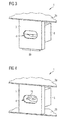
- FIG. 3 shows the housing 3 according to FIG. 1 , wherein on the housing wall 3 a part of a further housing wall 2a abuts.
- the housing wall 2a forms, for example, a kind of cover or cover in order to close off the housing 1 at the top.
- the housing wall 2a may form, for example, an upper cover plate of the housing 1.
- the housing 2a is applied to the housing 3 and acts with the upper slide 5a (see FIG. 2 ) mechanically together, so that the slide 5a of the in FIG. 2 moved down position shown.
- the part 5a of the cover of the opening 4 assigned to the slider 5a has also been moved downwards in a manner that lends itself to the opening 4 in the lower partial area.
- the second slider 5b is unchanged in the position according to FIG. 2 so that the opening 4 is at least partially covered or hidden by the slider 5b.
- a situation according to FIG. 3 is for example given by the fact that the housing 1 is indeed closed at an upper side with a housing wall 2a, but the underside of the housing 1 is still open.
- FIG. 4 shows the housing 3 of the housing 1, wherein in addition to the housing wall 2a at the top of the housing 1 is still a part of a further housing 2b is disposed on the underside of the housing 1.
- the housing wall 2b also bears against the housing wall 3.
- the housing 2b acts with the lower slide 5b (see Figures 2 and 3 ), so that the slider 5 b of the in the Figures 2 and 3 has been moved up position shown.
- the portion of the cover of the opening 4 associated with the lower slide 5b has been moved upward in a manner of a slide, so that according to FIG FIG. 4 the opening 4 is now completely opened.
- connection contacts 16 of a power supply terminal 6 are accessible, which is arranged within the housing 1 and, for example, to Connecting a computer system to a power grid is used.
- FIG. 4 A situation according to FIG. 4 is given for example by the fact that the housing 1 is completely closed by housing walls 2a and 2b. In this case, and only in this case, an external connector can be inserted through the opening 4 in the housing 1 and contacted with terminal contacts 16 of the power supply terminal 6.
- a housing 1 may also have only one slider. This could then extend over the entire cross section of an opening 4 and cover the opening 4, when a slider associated with the housing wall is opened. Furthermore, two slides could completely cover the opening 4 in each case, wherein the covering areas of the slides are arranged perpendicular to the cross section of the opening 4 one behind the other. Then, the opening 4 would always be completely covered when at least one housing wall is open, and opened only when the housing 1 is completely closed.
Landscapes
- Engineering & Computer Science (AREA)
- Theoretical Computer Science (AREA)
- Computer Hardware Design (AREA)
- Power Engineering (AREA)
- Human Computer Interaction (AREA)
- Physics & Mathematics (AREA)
- General Engineering & Computer Science (AREA)
- General Physics & Mathematics (AREA)
- Microelectronics & Electronic Packaging (AREA)
- Connector Housings Or Holding Contact Members (AREA)
- Casings For Electric Apparatus (AREA)
Applications Claiming Priority (1)
| Application Number | Priority Date | Filing Date | Title |
|---|---|---|---|
| DE102012100058A DE102012100058B3 (de) | 2012-01-04 | 2012-01-04 | Gehäuse für ein Computersystem sowie Computersystem mit einem derartigen Gehäuse |
Publications (2)
| Publication Number | Publication Date |
|---|---|
| EP2613219A2 true EP2613219A2 (fr) | 2013-07-10 |
| EP2613219A3 EP2613219A3 (fr) | 2016-06-15 |
Family
ID=47594414
Family Applications (1)
| Application Number | Title | Priority Date | Filing Date |
|---|---|---|---|
| EP12198617.8A Withdrawn EP2613219A3 (fr) | 2012-01-04 | 2012-12-20 | Boîtier de système informatique ainsi que système informatique doté d'un tel boîtier |
Country Status (4)
| Country | Link |
|---|---|
| US (1) | US9025320B2 (fr) |
| EP (1) | EP2613219A3 (fr) |
| JP (1) | JP2013140798A (fr) |
| DE (1) | DE102012100058B3 (fr) |
Cited By (1)
| Publication number | Priority date | Publication date | Assignee | Title |
|---|---|---|---|---|
| CN104795671A (zh) * | 2015-04-22 | 2015-07-22 | 苏州市时代工程咨询设计管理有限公司 | 一种电源插座 |
Families Citing this family (5)
| Publication number | Priority date | Publication date | Assignee | Title |
|---|---|---|---|---|
| US9595816B2 (en) * | 2014-12-23 | 2017-03-14 | Schneider Electric USA, Inc. | Safe use panelboard keyed shutter system |
| US9711886B2 (en) * | 2015-03-30 | 2017-07-18 | Honeywell International Inc. | SD card access door |
| WO2018136026A1 (fr) | 2017-01-17 | 2018-07-26 | Hewlett-Packard Development Company, L.P. | Verrouillage mécanique |
| EP3631903B1 (fr) * | 2017-05-30 | 2023-01-25 | Erico International Corporation | Adaptateur pour ouvertures de blocs d'épissure |
| JP2019179703A (ja) * | 2018-03-30 | 2019-10-17 | シャープ株式会社 | コネクタユニット |
Family Cites Families (13)
| Publication number | Priority date | Publication date | Assignee | Title |
|---|---|---|---|---|
| JP2651463B2 (ja) * | 1988-03-25 | 1997-09-10 | エヌシーアール インターナショナル インコーポレイテッド | インターロツク装置 |
| JPH02123677A (ja) * | 1988-10-27 | 1990-05-11 | Poirier Michel | 壁用コンセントの安全装置 |
| JPH0391674U (fr) * | 1989-12-28 | 1991-09-18 | ||
| DE9404326U1 (de) * | 1994-03-15 | 1994-05-19 | Wieshoff, Jürgen, 64291 Darmstadt | Zugangs-Verriegelung |
| JP3369080B2 (ja) | 1997-07-22 | 2003-01-20 | 富士通株式会社 | 電子装置 |
| DE29816033U1 (de) * | 1998-09-07 | 1998-11-26 | Siemens Nixdorf Informationssysteme AG, 33106 Paderborn | Verschlußkappenanordnung für ein Bedienfeld eines Steuer- oder Datenverarbeitungsgerätes |
| US6549397B1 (en) * | 2000-05-26 | 2003-04-15 | Hewlett-Packard Company | Tower computer with low center of gravity |
| US7264489B2 (en) | 2004-10-27 | 2007-09-04 | Hewlett-Packard Development Company, L.P. | Dual connector assembly with pivoting keep-out member |
| US7207812B1 (en) * | 2005-10-24 | 2007-04-24 | Hewlett-Packard Development Company, L.P. | Locking mechanism |
| DE102009019517A1 (de) * | 2009-04-30 | 2010-12-09 | Sinitec Vertriebsgesellschaft Mbh | Gehäuse für ein elektronisches Gerät |
| JP4949446B2 (ja) * | 2009-08-27 | 2012-06-06 | 東芝テック株式会社 | 感電防止機構及び感電防止機構を備える情報処理端末 |
| US8432679B2 (en) * | 2010-06-15 | 2013-04-30 | Apple Inc. | Silicone barrier for drive window |
| DE102012100056B3 (de) | 2012-01-04 | 2013-04-18 | Fujitsu Technology Solutions Intellectual Property Gmbh | Gehäuse für ein Computersystem sowie Computersystem mit einem derartigen Gehäuse |
-
2012
- 2012-01-04 DE DE102012100058A patent/DE102012100058B3/de not_active Expired - Fee Related
- 2012-12-20 EP EP12198617.8A patent/EP2613219A3/fr not_active Withdrawn
- 2012-12-28 JP JP2012287723A patent/JP2013140798A/ja active Pending
-
2013
- 2013-01-03 US US13/733,387 patent/US9025320B2/en not_active Expired - Fee Related
Non-Patent Citations (1)
| Title |
|---|
| None |
Cited By (1)
| Publication number | Priority date | Publication date | Assignee | Title |
|---|---|---|---|---|
| CN104795671A (zh) * | 2015-04-22 | 2015-07-22 | 苏州市时代工程咨询设计管理有限公司 | 一种电源插座 |
Also Published As
| Publication number | Publication date |
|---|---|
| DE102012100058B3 (de) | 2013-04-18 |
| JP2013140798A (ja) | 2013-07-18 |
| US20130171845A1 (en) | 2013-07-04 |
| US9025320B2 (en) | 2015-05-05 |
| EP2613219A3 (fr) | 2016-06-15 |
Similar Documents
| Publication | Publication Date | Title |
|---|---|---|
| DE69713871T2 (de) | Gehäuse ausgerüstet mit einem Verbinder für IC-Karte | |
| DE4438800C1 (de) | Anschlußklemmenblock mit Elektronikmodul | |
| DE102004038123B4 (de) | Elektrischer Stecker und elektrische Steckeraufnahme | |
| DE69417945T2 (de) | IC-Karten-Verbindungsvorrichtung mit Schalter | |
| EP2613220B1 (fr) | Boîtier pour système informatique et système informatique équipé d'un tel boîtier | |
| DE102012100058B3 (de) | Gehäuse für ein Computersystem sowie Computersystem mit einem derartigen Gehäuse | |
| DE102011014920A1 (de) | Universeller Steckeradapter mit verschiedenen Steckstiftsätzen | |
| EP3012920B1 (fr) | Prise electrique | |
| EP1943702A1 (fr) | Barrette a bornes | |
| DE102014107948B3 (de) | Steckverbinderanordnung und Kodierelement hierzu sowie Verfahren zur Kodierung einer Steckverbinderanordnung | |
| EP2625747B1 (fr) | Fiche de connexion supplémentaire | |
| DE3318137C2 (de) | Mehrpolige elektrische Steckvorrichtung | |
| WO2016075039A1 (fr) | Dispositif de contact rotatif pour un commutateur | |
| DE202014010621U1 (de) | Steckverbinder | |
| EP3756246A1 (fr) | Système de charge électrique pour charger des véhicules électriques | |
| DE10252829B4 (de) | Stromversorgung für ein elektrisches Gerät | |
| DE102013111577A1 (de) | Elektronikgerät | |
| EP1139493A2 (fr) | Connecteur électrique pour le raccordement de câbles à un appareil | |
| DE3928317C2 (de) | Elektrischer Gerätestecker | |
| EP3701272B1 (fr) | Barrette de raccordement | |
| DE102016116091A1 (de) | Elektrischer Anschlussverbinder mit Berührungsschutz | |
| DE112018005146B4 (de) | Elektrischer verbinderkörper vom hebeltyp und zugehörige elektrische verbinderanordnung | |
| AT517768B1 (de) | Überbrückungsvorrichtung für Zähleranschlussklemme | |
| DE102008014180A1 (de) | Trennklemme, insbesondere Neutralleiter-Trennklemme | |
| EP4057449B1 (fr) | Connecteur enfichable électrique |
Legal Events
| Date | Code | Title | Description |
|---|---|---|---|
| PUAI | Public reference made under article 153(3) epc to a published international application that has entered the european phase |
Free format text: ORIGINAL CODE: 0009012 |
|
| AK | Designated contracting states |
Kind code of ref document: A2 Designated state(s): AL AT BE BG CH CY CZ DE DK EE ES FI FR GB GR HR HU IE IS IT LI LT LU LV MC MK MT NL NO PL PT RO RS SE SI SK SM TR |
|
| AX | Request for extension of the european patent |
Extension state: BA ME |
|
| PUAL | Search report despatched |
Free format text: ORIGINAL CODE: 0009013 |
|
| AK | Designated contracting states |
Kind code of ref document: A3 Designated state(s): AL AT BE BG CH CY CZ DE DK EE ES FI FR GB GR HR HU IE IS IT LI LT LU LV MC MK MT NL NO PL PT RO RS SE SI SK SM TR |
|
| AX | Request for extension of the european patent |
Extension state: BA ME |
|
| RIC1 | Information provided on ipc code assigned before grant |
Ipc: G06F 1/18 20060101AFI20160509BHEP |
|
| STAA | Information on the status of an ep patent application or granted ep patent |
Free format text: STATUS: THE APPLICATION IS DEEMED TO BE WITHDRAWN |
|
| 18D | Application deemed to be withdrawn |
Effective date: 20161216 |