EP2614128B1 - Appareil et procédé de pyrolyse en lit fluidisé - Google Patents
Appareil et procédé de pyrolyse en lit fluidisé Download PDFInfo
- Publication number
- EP2614128B1 EP2614128B1 EP11782355.9A EP11782355A EP2614128B1 EP 2614128 B1 EP2614128 B1 EP 2614128B1 EP 11782355 A EP11782355 A EP 11782355A EP 2614128 B1 EP2614128 B1 EP 2614128B1
- Authority
- EP
- European Patent Office
- Prior art keywords
- pyrolysis
- combustion
- zone
- fluidised
- particles
- Prior art date
- Legal status (The legal status is an assumption and is not a legal conclusion. Google has not performed a legal analysis and makes no representation as to the accuracy of the status listed.)
- Active
Links
Images

Classifications
-
- C—CHEMISTRY; METALLURGY
- C10—PETROLEUM, GAS OR COKE INDUSTRIES; TECHNICAL GASES CONTAINING CARBON MONOXIDE; FUELS; LUBRICANTS; PEAT
- C10B—DESTRUCTIVE DISTILLATION OF CARBONACEOUS MATERIALS FOR PRODUCTION OF GAS, COKE, TAR, OR SIMILAR MATERIALS
- C10B49/00—Destructive distillation of solid carbonaceous materials by direct heating with heat-carrying agents including the partial combustion of the solid material to be treated
- C10B49/16—Destructive distillation of solid carbonaceous materials by direct heating with heat-carrying agents including the partial combustion of the solid material to be treated with moving solid heat-carriers in divided form
- C10B49/20—Destructive distillation of solid carbonaceous materials by direct heating with heat-carrying agents including the partial combustion of the solid material to be treated with moving solid heat-carriers in divided form in dispersed form
- C10B49/22—Destructive distillation of solid carbonaceous materials by direct heating with heat-carrying agents including the partial combustion of the solid material to be treated with moving solid heat-carriers in divided form in dispersed form according to the "fluidised bed" technique
-
- C—CHEMISTRY; METALLURGY
- C10—PETROLEUM, GAS OR COKE INDUSTRIES; TECHNICAL GASES CONTAINING CARBON MONOXIDE; FUELS; LUBRICANTS; PEAT
- C10B—DESTRUCTIVE DISTILLATION OF CARBONACEOUS MATERIALS FOR PRODUCTION OF GAS, COKE, TAR, OR SIMILAR MATERIALS
- C10B53/00—Destructive distillation, specially adapted for particular solid raw materials or solid raw materials in special form
- C10B53/02—Destructive distillation, specially adapted for particular solid raw materials or solid raw materials in special form of cellulose-containing material
-
- C—CHEMISTRY; METALLURGY
- C10—PETROLEUM, GAS OR COKE INDUSTRIES; TECHNICAL GASES CONTAINING CARBON MONOXIDE; FUELS; LUBRICANTS; PEAT
- C10K—PURIFYING OR MODIFYING THE CHEMICAL COMPOSITION OF COMBUSTIBLE GASES CONTAINING CARBON MONOXIDE
- C10K1/00—Purifying combustible gases containing carbon monoxide
- C10K1/08—Purifying combustible gases containing carbon monoxide by washing with liquids; Reviving the used wash liquors
- C10K1/16—Purifying combustible gases containing carbon monoxide by washing with liquids; Reviving the used wash liquors with non-aqueous liquids
-
- F—MECHANICAL ENGINEERING; LIGHTING; HEATING; WEAPONS; BLASTING
- F23—COMBUSTION APPARATUS; COMBUSTION PROCESSES
- F23C—METHODS OR APPARATUS FOR COMBUSTION USING FLUID FUEL OR SOLID FUEL SUSPENDED IN A CARRIER GAS OR AIR
- F23C10/00—Fluidised bed combustion apparatus
- F23C10/005—Fluidised bed combustion apparatus comprising two or more beds
-
- F—MECHANICAL ENGINEERING; LIGHTING; HEATING; WEAPONS; BLASTING
- F23—COMBUSTION APPARATUS; COMBUSTION PROCESSES
- F23C—METHODS OR APPARATUS FOR COMBUSTION USING FLUID FUEL OR SOLID FUEL SUSPENDED IN A CARRIER GAS OR AIR
- F23C10/00—Fluidised bed combustion apparatus
- F23C10/01—Fluidised bed combustion apparatus in a fluidised bed of catalytic particles
-
- F—MECHANICAL ENGINEERING; LIGHTING; HEATING; WEAPONS; BLASTING
- F23—COMBUSTION APPARATUS; COMBUSTION PROCESSES
- F23C—METHODS OR APPARATUS FOR COMBUSTION USING FLUID FUEL OR SOLID FUEL SUSPENDED IN A CARRIER GAS OR AIR
- F23C10/00—Fluidised bed combustion apparatus
- F23C10/18—Details; Accessories
- F23C10/20—Inlets for fluidisation air, e.g. grids; Bottoms
-
- F—MECHANICAL ENGINEERING; LIGHTING; HEATING; WEAPONS; BLASTING
- F23—COMBUSTION APPARATUS; COMBUSTION PROCESSES
- F23C—METHODS OR APPARATUS FOR COMBUSTION USING FLUID FUEL OR SOLID FUEL SUSPENDED IN A CARRIER GAS OR AIR
- F23C10/00—Fluidised bed combustion apparatus
- F23C10/18—Details; Accessories
- F23C10/24—Devices for removal of material from the bed
-
- Y—GENERAL TAGGING OF NEW TECHNOLOGICAL DEVELOPMENTS; GENERAL TAGGING OF CROSS-SECTIONAL TECHNOLOGIES SPANNING OVER SEVERAL SECTIONS OF THE IPC; TECHNICAL SUBJECTS COVERED BY FORMER USPC CROSS-REFERENCE ART COLLECTIONS [XRACs] AND DIGESTS
- Y02—TECHNOLOGIES OR APPLICATIONS FOR MITIGATION OR ADAPTATION AGAINST CLIMATE CHANGE
- Y02E—REDUCTION OF GREENHOUSE GAS [GHG] EMISSIONS, RELATED TO ENERGY GENERATION, TRANSMISSION OR DISTRIBUTION
- Y02E50/00—Technologies for the production of fuel of non-fossil origin
- Y02E50/10—Biofuels, e.g. bio-diesel
-
- Y—GENERAL TAGGING OF NEW TECHNOLOGICAL DEVELOPMENTS; GENERAL TAGGING OF CROSS-SECTIONAL TECHNOLOGIES SPANNING OVER SEVERAL SECTIONS OF THE IPC; TECHNICAL SUBJECTS COVERED BY FORMER USPC CROSS-REFERENCE ART COLLECTIONS [XRACs] AND DIGESTS
- Y02—TECHNOLOGIES OR APPLICATIONS FOR MITIGATION OR ADAPTATION AGAINST CLIMATE CHANGE
- Y02P—CLIMATE CHANGE MITIGATION TECHNOLOGIES IN THE PRODUCTION OR PROCESSING OF GOODS
- Y02P20/00—Technologies relating to chemical industry
- Y02P20/10—Process efficiency
- Y02P20/129—Energy recovery, e.g. by cogeneration, H2recovery or pressure recovery turbines
-
- Y—GENERAL TAGGING OF NEW TECHNOLOGICAL DEVELOPMENTS; GENERAL TAGGING OF CROSS-SECTIONAL TECHNOLOGIES SPANNING OVER SEVERAL SECTIONS OF THE IPC; TECHNICAL SUBJECTS COVERED BY FORMER USPC CROSS-REFERENCE ART COLLECTIONS [XRACs] AND DIGESTS
- Y02—TECHNOLOGIES OR APPLICATIONS FOR MITIGATION OR ADAPTATION AGAINST CLIMATE CHANGE
- Y02P—CLIMATE CHANGE MITIGATION TECHNOLOGIES IN THE PRODUCTION OR PROCESSING OF GOODS
- Y02P20/00—Technologies relating to chemical industry
- Y02P20/141—Feedstock
- Y02P20/145—Feedstock the feedstock being materials of biological origin
Definitions
- the invention relates to the pyrolysis of carbonaceous material, such as bio-mass, in a fluidised bed pyrolysis apparatus.
- Fast pyrolysis of bio-mass involves rapidly heating solid bio-mass to a temperature of 400°C to 600°C in reducing conditions so that it forms an oil. This is typically done in a fluidised bed, where approximately 60% of the original biomass can be recovered as oil.
- the pyrolysis is endothermic in nature, and the energy required is typically obtained by heating the fluidised bed indirectly, using electrical heating elements.
- the source of heat for heating the fluidised bed is sand which is heating using electrical heating elements to provide the energy for the endothermic reaction. Electrical energy is continuously required in order to maintain the pyrolysis reaction.
- char produced by the pyrolysis of the bio-mass is recycled as a fuel to the pyrolysis reaction where it is combusted to provide some of the energy required to maintain the pyrolysis temperature, however, this is done at the expense of the char being lost.
- United States patent US 4,311,670 discloses a process and apparatus for pyrolysis and combustion, wherein flue gases have a temperature of about 900°C and pyrolysis is carried out at a temperature of about 700°C.
- German patent application DE 195 17 096 A1 discloses the replacement of bed material (quartz sand) by zeolithes.
- the inventors have thus identified a need for a more efficient pyrolysis apparatus for the pyrolysis of bio-mass while reducing the need for an external energy source and possibly allowing for some or all of the char thus produced to be retained for alternative use rather than as a fuel to the pyrolysis.
- a carbonaceous feed pyrolysis apparatus including two or more hot particle fluidised beds, and one or more positive displacement apparatus for the transfer of hot particles between two or more of the beds, wherein one or more of the fluidised beds contains a combustion zone, and wherein one or more of the fluidised beds contains a pyrolysis zone, and wherein the apparatus includes one or more valve means between the combustion and pyrolysis zones so that hot particles flow from the combustion zone or zones to the pyrolysis zone or zones while impeding the flow of gas in the opposite direction, wherein the valve is a non-mechanical valve with a bottom pipe section making use of an angle between 120° and 150° from the vertical, typically 135° from the vertical, between the combustion and pyrolysis zones so that hot particles flow from the combustion zone or zones to the pyrolysis zone or zones while impeding the flow of gas in the opposite direction.
- a bio-oil production process including pyrolysis of a carbonaceous bio-mass, which process includes the use of a carbonaceous feed pyrolysis apparatus as indicated above, said apparatus comprising two or more fluidised beds, a first combustion zone carried out in one or more combustion fluidised beds in which a particulate material is fluidised and heated, and a second pyrolysis zone carried out in one or more pyrolysis fluidised beds in which the hot particles heated in the combustion zone are used for pyrolysis of the bio-mass, said combustion zone being operated at or about atmospheric pressure at a temperature of from 400°C to 1100°C, typically around 900°C, and the pyrolysis zone being operated at a pressure of from atmospheric to 100 Barg at a temperature of from 400°C to 900°C, typically 500°C to 600°C.
- the positive displacement apparatus may be a screw feeder or the like.
- the screw feeder may be driven by a variable speed drive motor or a constant speed drive motor.
- the hot particles in the fluidised beds may be sand particles.
- the hot particles in the fluidised beds may be primarily catalyst particles.
- the use of catalyst in the pyrolysis zone may allow more throughput of bio-mass because more CO 2 is produced and therefore the reaction will be less endothermic.
- the catalyst particles may be zeolite particles.
- the catalyst particles are typically cracking catalyst particles, such as acidic zeolite particles.
- the apparatus as described above includes a recycle duct for gas produced in the pyrolysis zone to the combustion zone for combustion for the heating of the hot particles.
- Pyrolysis gas from the pyrolysis zone may be at least partially recycled to the combustion zone as a source of fuel for the combustion used to heat the particles.
- the combustion fluidised bed and the pyrolysis fluidised bed include fluidised bed nozzles whereby the fluidising gas for the pyrolysis fluidised bed, or the fluidising gas as well as or any of combustion gases for the combustion fluidised bed, respectively, are injected into the fluidised beds through one or more nozzles at a base portion of the fluidised beds.
- the nozzle arrangement is selected rather than the standard plenum arrangement permitting removal of the hot particles from the base of the fluidised beds by the positive displacement apparatus with a smaller hold up volume as the hot particles drop past the nozzles for extraction.
- Air may enter downwards or upwards through the nozzles into the fluidised beds.
- Horizontal jets may prevent sand from flowing into an air supply line.
- the recycle gas duct or line may enter as close as possible to the nozzle, where it mixes with cold air, and combusts in the fluidised bed.
- the apparatus may include a char separator after the pyrolysis fluidised bed whereby char can be captured.
- the captured char may be recycled to the combustion fluidised bed or be used for other purposes unrelated to the operation of the pyrolysis apparatus.
- the char separator may be a cyclone.
- the area of the combustion fluidized bed may be 2-6 times larger than that of the pyrolysis bed, typically 3 - 4 time larger. This may be more energy-efficient because less of the enthalpy available from the hot particles is used to re-heat the recycled gases, and more enthalpy is used to drive the endothermic pyrolysis reaction.
- the superficial gas velocity (SGV) may be high in the combustion fluidised bed at a rate of from 1 m/s to 4 m/s, typically 2 m/s, in order to burn as much oxygen as possible in a bed of a given area.
- the superficial gas velocity of the recycle pyrolysis gas may be as low as possible while still achieving good fluidisation and thus mixing.
- the SGV in the pyrolysis fluidised bed may be from 0.2 to 2 m/s, typically 0.5 m/s. It is believed that in this way less enthalpy is lost by means of heating the cold recycle gas.
- the bio-mass also enters as a solid, and leaves as a gas, thereby increasing the superficial gas velocity as the pyrolysis reaction occurs.
- the SGV of the recycled pyrolysis gas is controlled or selected in relation to the degree of entrainment of hot particles in the combustion zone and thus if high entrainment occurs at 2.5 m/s, for instance, a low SGV of recycle pyrolysis gas can be selected in order to allow larger throughput of biomass before SGV gets unacceptably high due to vapourization of biomass.
- Air supply to the fluidized bed may be preheated by exchanging heat from the gases exiting the combustion zone. This may substantially reduce the fluidized bed area required in the combustion zone to heat a given mass flow rate of hot particles. It also may reduce the amount of carbon that is combusted to form CO 2 , making the process more environmentally friendly.
- the temperature of the combustion fluidized bed may be controlled by varying the rate of transfer of hot particles from the pyrolysis zone to the combustion zone, for example, by varying the speed of a motor driving the positive displacement apparatus such as a screw feeder used for the purpose.
- the air flow rate is typically fixed to provide a constant SGV through the combustion zone.
- Fuel flow rate (recycle gas) may be adjusted in order to ensure that there is always sufficient excess oxygen in the gas exiting from the combustion chamber. This may be estimated by measuring CO 2 concentration in the exit gases and inferring excess oxygen.
- the temperature in the pyrolysis zone is controlled by varying the rate of bio-mass entering the pyrolysis zone.
- the recycle gas flow rate is typically fixed in order to ensure adequate fluidization in the pyrolysis fluidized bed.
- the fluidised beds may include disengagement zones.
- the pressure in the disengagement zones of both the pyrolysis and combustion fluidised beds may be close to atmospheric pressure because of the difficulty of adequate sealing at high temperatures.
- the pressure in the disengagement zone may be controlled by controlling the speed of an induced draft (ID) fan or by controlling a damper setting in a low pressure line.
- ID induced draft
- the pressure in the pyrolysis zone may be controlled by varying the amount of purge gas released from the recycle gas stream.
- the combustion zone also serves to regenerate the catalyst as it burns off any coke formed in the pores of the particles during pyrolysis.
- a pyrolysis apparatus 12 and a pyrolysis process is provided for rapidly heating bio-mass to be pyrolysed to bio-oil by mixing it in a pyrolysis fluidised bed 14 with hot particles, in the form of hot sand 16, from a separate fluidised bed operating in combustion conditions.
- the combustion fluidised bed 18 has a cross sectional area 3 to 4 times that of the cross sectional area of the pyrolysis fluidised bed 14.
- the combustion fluidised bed 18 is kept hot, typically around 900°C, by burning combustible gas and char.
- the hot sand 16 moves from the combustion region 15 to the pyrolysis region 17 by means of an "L" valve 20 which is known in fluidised bed technology.
- the pyrolysis reaction cools the sand down to 500-600°C, and the cooled sand is returned by a screw conveyor 22 to the hot combustion fluidised bed 18 for reheating.
- Some char is entrained with the sand although most of the char will be entrained with the gas and will be collected by the cyclone 24.
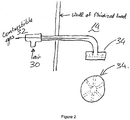
- the char in the sand will burn in the fluidised bed, to provide at least part of the required energy. More energy can be provided from the purge of the pyrolysis gas loop 26. 2/3 of the energy required for combustion can come from the pyrolysis gases which are combustible gases. These gases are introduced directly into the fluidised bed nozzles 28 with the recycle pyrolysis gas being fed concentricly with the air supply pipe into the fluidised bed gas feed pipes to the fluidised bed nozzles . It is preferable to use the gas as the heat source thereby saving the char, because the char is a valuable resource for farmers; it improves the soil when it is worked in.
- the air 30 may enter the fluidised beds 14, 18 through the nozzles either downwards, as indicated, or upwards.
- the horizontal jets are designed to prevent sand from flowing into the air supply line.
- the gas line 32 enters as close as possible to the nozzle 34 (28), where it mixes with cold air, and combusts in the fluidized bed.
- the sand 16 that is used for the bed of the fluidised beds 14, 18 of the first embodiment is replaced with catalyst that provides a more stable bio-oil than using sand alone.
- the oxygen content in the oil can be reduced in this way (being removed as CO 2 .
- the catalytically treated oil can be blended into refinery feedstocks to form transportation fuel.
- the dual fluidised bed system provides the ideal circumstances for continuous regeneration of the pyrolysis catalyst as the catalyst particles which are returned by the screw feeder to the combustion fluidised bed are heated to around 900°C which regenerates the catalyst continuously.
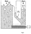
- the non-mechanical "Z" valve 36 design makes use of an angle closer to 135°, as shown between Bed A 38 (equivalent to 18 in Figure 1 ) and Bed B 40 (equivalent to 14 in Figure 1 ) in Figure 3 . This allows for the unassisted transport of solids through the valve as only gravity is required as the driving force for the flow of solids.
Landscapes
- Engineering & Computer Science (AREA)
- Chemical & Material Sciences (AREA)
- Combustion & Propulsion (AREA)
- Oil, Petroleum & Natural Gas (AREA)
- General Engineering & Computer Science (AREA)
- Mechanical Engineering (AREA)
- Organic Chemistry (AREA)
- Materials Engineering (AREA)
- Chemical Kinetics & Catalysis (AREA)
- Dispersion Chemistry (AREA)
- General Chemical & Material Sciences (AREA)
- Production Of Liquid Hydrocarbon Mixture For Refining Petroleum (AREA)
- Processing Of Solid Wastes (AREA)
- Devices And Processes Conducted In The Presence Of Fluids And Solid Particles (AREA)
Claims (14)
- Appareil de pyrolyse de charge carbonée comprenant deux ou plusieurs lits fluidisés à particules chaudes, et au moins un appareil à déplacement positif conçu pour transférer des particules chaudes entre deux ou plusieurs des lits (B 40; A 38), un ou plusieurs des lits fluidisés (B 40; A 38) comprenant une zone de combustion et un ou plusieurs des lits fluidisés (B 40; A 38) comprenant une zone de pyrolyse,
caractérisé en ce que
l'appareil comprend une ou plusieurs vannes (36) entre les zones de combustion et de pyrolyse de telle sorte que des particules chaudes écoulent depuis la zone ou des zones de combustion vers la/les zone(s) de pyrolyse tout en entravant le débit de gaz dans la direction opposée, la vanne (36) étant une vanne non mécanique avec une section de tuyau de fond utilisant un angle compris entre 120º et 150º par rapport à la verticale, normalement 135º par rapport à la verticale, entre les zones de combustion et de pyrolyse de sorte que des particules chaudes écoulent depuis la zone ou des zones de combustion vers la/les zone(s) de pyrolyse tout en entravant le débit de gaz dans la direction opposée. - Appareil selon la revendication 1, dans lequel le lit fluidisé de combustion (A 38) et le lit fluidisé de pyrolyse (B 40) comprennent des buses pour lits fluidisés, le gaz de fluidisation destiné au lit fluidisé de pyrolyse (B 40), ou le gaz de fluidisation aussi bien que tout gaz de combustion destinés au lit fluidisé de combustion (A 38), respectivement, étant injectés dans les lits fluidisés (A 38; B 40) à travers un ou plusieurs buses au niveau de la partie du fond des lits fluidisés (A 38; A 40).
- Appareil selon la revendication 2, dans lequel l'agencement des buses permet le retrait des particules chaudes depuis la base des lits fluidisés (B 40; A 38) par l'intermédiaire de l'appareil de déplacement positif ayant un plus petit volume de rétention pendant que les particules chaudes chutent au-delà des buses pour l'extraction.
- Appareil selon l'une quelconque des revendications 1 à 3, l'appareil comportant un séparateur de charbon de bois en aval du lit fluidisé de pyrolyse (B 40), lequel saisit le charbon de bois.
- Procédé de production de bio-huile, ledit procédé comprenant la pyrolyse d'une biomasse carbonée, ledit procédé comprenant l'utilisation d'un appareil de pyrolyse de charge carbonée selon l'une quelconque des revendications 1 à 4, ledit appareil comprenant deux ou plusieurs lits fluidisés (B 40; A 38), une première zone de combustion mise en oeuvre dans au moins un lits fluidisé de combustion (A 38) dans lequel une matière sous forme de particules est fluidisée et chauffée, et une seconde zone de pyrolyse mise en oeuvre dans au moins un lit fluidisé de pyrolyse (B 40) dans lequel les particules chaudes chauffées dans la zone de combustion sont utilisées pour la pyrolyse de la biomasse, ladite zone de combustion fonctionnant à une pression égale à la pression atmosphérique ou proche de celle-ci à une température comprise entre 400ºC et 1100ºC, généralement autour de 900ºC, et la zone de pyrolyse fonctionnant à une pression comprise entre la pression atmosphérique et 100 bar (pression manométrique) à une température comprise entre 400ºC et 900ºC.
- Procédé selon la revendication 5, dans lequel le gaz de pyrolyse provenant de la zone de pyrolyse est recyclé au moins partiellement vers la zone de combustion en tant que source de combustible destiné à la combustion, utilisée pour chauffer les particules.
- Procédé selon les revendications 5 ou 6, dans lequel les particules chaudes sont des particules de catalyseur de telle sorte que l'utilisation du catalyseur dans la zone de pyrolyse permet un meilleur débit de biomasse, vu que plus de CO2 est produit et, par conséquent, la réaction sera moins endothermique.
- Procédé selon l'une quelconque des revendications 5 à 7, dans lequel la zone de pyrolyse fonctionne à ou proche de la pression atmosphérique.
- Procédé selon la revendication 7, dans lequel le catalyseur est un catalyseur de craquage destiné à l'extraction.
- Procédé selon la revendication 9, dans lequel le catalyseur est un catalyseur à zéolite acide.
- Procédé selon l'une quelconque des revendications 5 à 10, dans lequel la région du lit fluidisé de combustion (A 38) est 2 à 6 fois plus grande que le lit de pyrolyse (B 40).
- Procédé selon l'une quelconque des revendications 5 à 11, dans lequel la vitesse de gaz superficielle (SGV superficial gas velocity) du gaz de pyrolyse recyclé est réglée ou sélectionnée par rapport au degré de l'entraînement des particules chaudes dans la zone de combustion.
- Procédé selon l'une quelconque des revendications 5 à 12, dans lequel la température du lit fluidisé de combustion (A 38) est contrôlée en faisant varier le taux de transfert de particules chaudes depuis la zone de pyrolyse vers la zone de combustion.
- Procédé selon l'une quelconque des revendications 5 à 13, dans lequel, lorsque des particules de catalyseur sont utilisées comme les particules chaudes, la zone de combustion sert également à régénérer le catalyseur alors qu'il brûle tout coke formé dans les pores des particules pendant la pyrolyse.
Applications Claiming Priority (2)
| Application Number | Priority Date | Filing Date | Title |
|---|---|---|---|
| US38191710P | 2010-09-10 | 2010-09-10 | |
| PCT/ZA2011/000067 WO2012034141A1 (fr) | 2010-09-10 | 2011-09-08 | Appareil et procédé de pyrolyse en lit fluidisé |
Publications (2)
| Publication Number | Publication Date |
|---|---|
| EP2614128A1 EP2614128A1 (fr) | 2013-07-17 |
| EP2614128B1 true EP2614128B1 (fr) | 2019-08-21 |
Family
ID=44947268
Family Applications (1)
| Application Number | Title | Priority Date | Filing Date |
|---|---|---|---|
| EP11782355.9A Active EP2614128B1 (fr) | 2010-09-10 | 2011-09-08 | Appareil et procédé de pyrolyse en lit fluidisé |
Country Status (5)
| Country | Link |
|---|---|
| US (1) | US9580657B2 (fr) |
| EP (1) | EP2614128B1 (fr) |
| BR (1) | BR112013005718B1 (fr) |
| CA (1) | CA2810724C (fr) |
| WO (1) | WO2012034141A1 (fr) |
Families Citing this family (17)
| Publication number | Priority date | Publication date | Assignee | Title |
|---|---|---|---|---|
| GB2503065B (en) * | 2013-02-20 | 2014-11-05 | Recycling Technologies Ltd | Process and apparatus for treating waste comprising mixed plastic waste |
| US9434885B2 (en) | 2013-02-26 | 2016-09-06 | The United States Of America, As Represented By The Secretary Of Agriculture | Methods for producing bio-oil |
| EP3008153B1 (fr) | 2013-06-14 | 2020-08-05 | University Of Pretoria | Appareil pour des réactions endothermiques |
| FR3029979B1 (fr) * | 2014-12-12 | 2019-04-05 | IFP Energies Nouvelles | Procede et installation de combustion par oxydo-reduction en boucle chimique d'une charge hydrocarbonee gazeuse avec reformage catalytique in situ de la charge |
| JP6809197B2 (ja) * | 2016-12-16 | 2021-01-06 | 株式会社Ihi | 流動層システム |
| FI127753B (en) | 2017-06-09 | 2019-01-31 | Bioshare Ab | Recycling of chemicals from fuel streams |
| CN110437858A (zh) * | 2019-08-26 | 2019-11-12 | 华南理工大学 | 一种催化剂可再生的微波辅助催化快速热解生活垃圾的方法与装置 |
| GB2588384A (en) * | 2019-10-16 | 2021-04-28 | Recycling Tech Ltd | Improvements in and relating to reactor fluid supply systems |
| US12319878B2 (en) | 2020-08-06 | 2025-06-03 | Chevron U.S.A. Inc. | Upgrading of low value lipid feedstocks for refinery processing |
| EP4211201A1 (fr) | 2020-09-14 | 2023-07-19 | University Of Pretoria | Appareil et procédé de pyrolyse en lit fluidisé |
| AU2021107412A4 (en) * | 2021-06-23 | 2021-12-23 | SEATA Holdings Pty Ltd | Process of treating carbonaceous material and apparatus therefor |
| EP4209710A1 (fr) * | 2022-01-10 | 2023-07-12 | ICMEA Srl leader of temporary association of companies ICMEA Srl - Tecnomec Engineering Srl - CNR IRSA | Unité de lit fluidisé |
| US12421460B2 (en) | 2024-01-15 | 2025-09-23 | Chevron U.S.A. Inc. | Downflow lipid conversion with upflow catalyst regeneration |
| WO2025155623A1 (fr) | 2024-01-16 | 2025-07-24 | Chevron U.S.A. Inc. | Sélection de catalyseur pour conversion améliorée de charge d'alimentation lipidique |
| US12319881B1 (en) | 2024-09-27 | 2025-06-03 | Chevron U.S.A. Inc. | Converting a renewable fuel intermediate composition to finished transportation fuel |
| US12582954B1 (en) | 2024-12-13 | 2026-03-24 | Chevron U.S.A. Inc. | Processing feedstocks |
| US12590258B1 (en) | 2025-02-28 | 2026-03-31 | Chevron U.S.A. Inc. | Converting a lipid feedstock to fuel |
Family Cites Families (7)
| Publication number | Priority date | Publication date | Assignee | Title |
|---|---|---|---|---|
| GB1448196A (en) * | 1972-10-20 | 1976-09-02 | Sprocket Properties Ltd | Fluidised bed incinerators |
| GB1561237A (en) * | 1976-09-22 | 1980-02-13 | Ahlstroem Oy | Method of treating materials in a fluidized bed reactor |
| US4279207A (en) * | 1979-04-20 | 1981-07-21 | Wormser Engineering, Inc. | Fluid bed combustion |
| US4823712A (en) | 1985-12-18 | 1989-04-25 | Wormser Engineering, Inc. | Multifuel bubbling bed fluidized bed combustor system |
| FI931785A7 (fi) * | 1993-04-20 | 1994-10-21 | Valtion Teknillinen | Menetelmä ja laitteisto nestemäisen polttoaineen valmistamiseksi pyrolysoimalla raakapolttoainetta |
| DE19517096A1 (de) | 1995-05-10 | 1996-11-14 | Daniel Engelhardt | Zeolithkatalysierte Pyrolyse von Kunststoffen |
| BR112012005379B1 (pt) * | 2009-09-09 | 2019-03-06 | University Of Massachusetts | Sistemas e processos para pirólise catalítica de biomassa e materiais hidrocarboníferos para produção de aromáticos com reciclagem de olefina opcional e catalisadores tendo tamanho de partícula selecionado para pirólise catalítica. |
-
2011
- 2011-09-08 US US13/820,721 patent/US9580657B2/en active Active
- 2011-09-08 EP EP11782355.9A patent/EP2614128B1/fr active Active
- 2011-09-08 BR BR112013005718A patent/BR112013005718B1/pt active IP Right Grant
- 2011-09-08 WO PCT/ZA2011/000067 patent/WO2012034141A1/fr not_active Ceased
- 2011-09-08 CA CA2810724A patent/CA2810724C/fr active Active
Non-Patent Citations (1)
| Title |
|---|
| None * |
Also Published As
| Publication number | Publication date |
|---|---|
| WO2012034141A1 (fr) | 2012-03-15 |
| WO2012034141A4 (fr) | 2012-05-03 |
| CA2810724A1 (fr) | 2012-03-15 |
| BR112013005718A2 (pt) | 2017-04-04 |
| CA2810724C (fr) | 2018-05-01 |
| US9580657B2 (en) | 2017-02-28 |
| CN103180412A (zh) | 2013-06-26 |
| BR112013005718B1 (pt) | 2019-12-24 |
| US20140008205A1 (en) | 2014-01-09 |
| EP2614128A1 (fr) | 2013-07-17 |
Similar Documents
| Publication | Publication Date | Title |
|---|---|---|
| CA2810724C (fr) | Appareil et procede de pyrolyse en lit fluidise | |
| US10794588B2 (en) | Apparatuses for controlling heat for rapid thermal processing of carbonaceous material and methods for the same | |
| US20100162625A1 (en) | Biomass fast pyrolysis system utilizing non-circulating riser reactor | |
| CN106010672A (zh) | 热解系统中的炭处理方法 | |
| JP2019518011A (ja) | 糖の熱分解性フラグメンテーション | |
| CN112513225A (zh) | 热解反应系统和热解有机进料的方法 | |
| CN101358136A (zh) | 油砂直接流化床焦化的方法和装置 | |
| JP2025100680A (ja) | 炭素質材料を処理する方法およびそのための装置 | |
| CN105316014A (zh) | 热解生物质的方法和系统 | |
| CN105273731A (zh) | 一种生物质热解联产燃气/生物炭装置及工艺 | |
| US5915311A (en) | Process for the thermal treatment of waste material | |
| US20230357641A1 (en) | Fluidised bed pyrolysis apparatus and method | |
| US4413573A (en) | Process for combusting carbonaceous solids containing nitrogen | |
| CN105331377A (zh) | 热解煤的方法和系统 | |
| WO2014049587A1 (fr) | Dispositif pour la valorisation de matières organiques solides | |
| JP3954816B2 (ja) | ガス供給装置及びガス供給方法 | |
| JPS58171483A (ja) | 固体炭素質粒子の熱分解法およびこれに用いるレトルト熱分解装置 | |
| JP2007217696A (ja) | 素材製造システム及びガス供給方法 | |
| AU2021107412A4 (en) | Process of treating carbonaceous material and apparatus therefor | |
| JP3990897B2 (ja) | ガス供給装置及びガス供給方法 | |
| KR102029315B1 (ko) | 철-옥사이드 함유 공급 원료를 환원시키기 위한 방법 및 디바이스 | |
| CN103180412B (zh) | 流化床裂解装置和方法 | |
| CN115557500B (zh) | 一种物理法制备活性炭的多膛循环流化活化一体炉装置及方法 | |
| CA1127575A (fr) | Methode et dispositif de pyrogenation d'une substance a teneur matiere organique | |
| CN109504414A (zh) | 一种多层式干馏热解炉 |
Legal Events
| Date | Code | Title | Description |
|---|---|---|---|
| PUAI | Public reference made under article 153(3) epc to a published international application that has entered the european phase |
Free format text: ORIGINAL CODE: 0009012 |
|
| 17P | Request for examination filed |
Effective date: 20130403 |
|
| AK | Designated contracting states |
Kind code of ref document: A1 Designated state(s): AL AT BE BG CH CY CZ DE DK EE ES FI FR GB GR HR HU IE IS IT LI LT LU LV MC MK MT NL NO PL PT RO RS SE SI SK SM TR |
|
| DAX | Request for extension of the european patent (deleted) | ||
| 17Q | First examination report despatched |
Effective date: 20140131 |
|
| STAA | Information on the status of an ep patent application or granted ep patent |
Free format text: STATUS: EXAMINATION IS IN PROGRESS |
|
| TPAC | Observations filed by third parties |
Free format text: ORIGINAL CODE: EPIDOSNTIPA |
|
| GRAP | Despatch of communication of intention to grant a patent |
Free format text: ORIGINAL CODE: EPIDOSNIGR1 |
|
| STAA | Information on the status of an ep patent application or granted ep patent |
Free format text: STATUS: GRANT OF PATENT IS INTENDED |
|
| INTG | Intention to grant announced |
Effective date: 20190311 |
|
| GRAS | Grant fee paid |
Free format text: ORIGINAL CODE: EPIDOSNIGR3 |
|
| GRAA | (expected) grant |
Free format text: ORIGINAL CODE: 0009210 |
|
| STAA | Information on the status of an ep patent application or granted ep patent |
Free format text: STATUS: THE PATENT HAS BEEN GRANTED |
|
| AK | Designated contracting states |
Kind code of ref document: B1 Designated state(s): AL AT BE BG CH CY CZ DE DK EE ES FI FR GB GR HR HU IE IS IT LI LT LU LV MC MK MT NL NO PL PT RO RS SE SI SK SM TR |
|
| REG | Reference to a national code |
Ref country code: GB Ref legal event code: FG4D |
|
| REG | Reference to a national code |
Ref country code: CH Ref legal event code: EP |
|
| REG | Reference to a national code |
Ref country code: DE Ref legal event code: R096 Ref document number: 602011061450 Country of ref document: DE |
|
| REG | Reference to a national code |
Ref country code: AT Ref legal event code: REF Ref document number: 1169754 Country of ref document: AT Kind code of ref document: T Effective date: 20190915 |
|
| REG | Reference to a national code |
Ref country code: IE Ref legal event code: FG4D |
|
| REG | Reference to a national code |
Ref country code: LT Ref legal event code: MG4D |
|
| REG | Reference to a national code |
Ref country code: NL Ref legal event code: MP Effective date: 20190821 |
|
| PG25 | Lapsed in a contracting state [announced via postgrant information from national office to epo] |
Ref country code: FI Free format text: LAPSE BECAUSE OF FAILURE TO SUBMIT A TRANSLATION OF THE DESCRIPTION OR TO PAY THE FEE WITHIN THE PRESCRIBED TIME-LIMIT Effective date: 20190821 Ref country code: NO Free format text: LAPSE BECAUSE OF FAILURE TO SUBMIT A TRANSLATION OF THE DESCRIPTION OR TO PAY THE FEE WITHIN THE PRESCRIBED TIME-LIMIT Effective date: 20191121 Ref country code: BG Free format text: LAPSE BECAUSE OF FAILURE TO SUBMIT A TRANSLATION OF THE DESCRIPTION OR TO PAY THE FEE WITHIN THE PRESCRIBED TIME-LIMIT Effective date: 20191121 Ref country code: SE Free format text: LAPSE BECAUSE OF FAILURE TO SUBMIT A TRANSLATION OF THE DESCRIPTION OR TO PAY THE FEE WITHIN THE PRESCRIBED TIME-LIMIT Effective date: 20190821 Ref country code: PT Free format text: LAPSE BECAUSE OF FAILURE TO SUBMIT A TRANSLATION OF THE DESCRIPTION OR TO PAY THE FEE WITHIN THE PRESCRIBED TIME-LIMIT Effective date: 20191223 Ref country code: HR Free format text: LAPSE BECAUSE OF FAILURE TO SUBMIT A TRANSLATION OF THE DESCRIPTION OR TO PAY THE FEE WITHIN THE PRESCRIBED TIME-LIMIT Effective date: 20190821 Ref country code: LT Free format text: LAPSE BECAUSE OF FAILURE TO SUBMIT A TRANSLATION OF THE DESCRIPTION OR TO PAY THE FEE WITHIN THE PRESCRIBED TIME-LIMIT Effective date: 20190821 Ref country code: NL Free format text: LAPSE BECAUSE OF FAILURE TO SUBMIT A TRANSLATION OF THE DESCRIPTION OR TO PAY THE FEE WITHIN THE PRESCRIBED TIME-LIMIT Effective date: 20190821 |
|
| PG25 | Lapsed in a contracting state [announced via postgrant information from national office to epo] |
Ref country code: AL Free format text: LAPSE BECAUSE OF FAILURE TO SUBMIT A TRANSLATION OF THE DESCRIPTION OR TO PAY THE FEE WITHIN THE PRESCRIBED TIME-LIMIT Effective date: 20190821 Ref country code: LV Free format text: LAPSE BECAUSE OF FAILURE TO SUBMIT A TRANSLATION OF THE DESCRIPTION OR TO PAY THE FEE WITHIN THE PRESCRIBED TIME-LIMIT Effective date: 20190821 Ref country code: ES Free format text: LAPSE BECAUSE OF FAILURE TO SUBMIT A TRANSLATION OF THE DESCRIPTION OR TO PAY THE FEE WITHIN THE PRESCRIBED TIME-LIMIT Effective date: 20190821 Ref country code: GR Free format text: LAPSE BECAUSE OF FAILURE TO SUBMIT A TRANSLATION OF THE DESCRIPTION OR TO PAY THE FEE WITHIN THE PRESCRIBED TIME-LIMIT Effective date: 20191122 Ref country code: RS Free format text: LAPSE BECAUSE OF FAILURE TO SUBMIT A TRANSLATION OF THE DESCRIPTION OR TO PAY THE FEE WITHIN THE PRESCRIBED TIME-LIMIT Effective date: 20190821 Ref country code: IS Free format text: LAPSE BECAUSE OF FAILURE TO SUBMIT A TRANSLATION OF THE DESCRIPTION OR TO PAY THE FEE WITHIN THE PRESCRIBED TIME-LIMIT Effective date: 20191221 |
|
| REG | Reference to a national code |
Ref country code: AT Ref legal event code: MK05 Ref document number: 1169754 Country of ref document: AT Kind code of ref document: T Effective date: 20190821 |
|
| PG25 | Lapsed in a contracting state [announced via postgrant information from national office to epo] |
Ref country code: TR Free format text: LAPSE BECAUSE OF FAILURE TO SUBMIT A TRANSLATION OF THE DESCRIPTION OR TO PAY THE FEE WITHIN THE PRESCRIBED TIME-LIMIT Effective date: 20190821 |
|
| PG25 | Lapsed in a contracting state [announced via postgrant information from national office to epo] |
Ref country code: RO Free format text: LAPSE BECAUSE OF FAILURE TO SUBMIT A TRANSLATION OF THE DESCRIPTION OR TO PAY THE FEE WITHIN THE PRESCRIBED TIME-LIMIT Effective date: 20190821 Ref country code: PL Free format text: LAPSE BECAUSE OF FAILURE TO SUBMIT A TRANSLATION OF THE DESCRIPTION OR TO PAY THE FEE WITHIN THE PRESCRIBED TIME-LIMIT Effective date: 20190821 Ref country code: AT Free format text: LAPSE BECAUSE OF FAILURE TO SUBMIT A TRANSLATION OF THE DESCRIPTION OR TO PAY THE FEE WITHIN THE PRESCRIBED TIME-LIMIT Effective date: 20190821 Ref country code: DK Free format text: LAPSE BECAUSE OF FAILURE TO SUBMIT A TRANSLATION OF THE DESCRIPTION OR TO PAY THE FEE WITHIN THE PRESCRIBED TIME-LIMIT Effective date: 20190821 Ref country code: EE Free format text: LAPSE BECAUSE OF FAILURE TO SUBMIT A TRANSLATION OF THE DESCRIPTION OR TO PAY THE FEE WITHIN THE PRESCRIBED TIME-LIMIT Effective date: 20190821 Ref country code: IT Free format text: LAPSE BECAUSE OF FAILURE TO SUBMIT A TRANSLATION OF THE DESCRIPTION OR TO PAY THE FEE WITHIN THE PRESCRIBED TIME-LIMIT Effective date: 20190821 |
|
| PG25 | Lapsed in a contracting state [announced via postgrant information from national office to epo] |
Ref country code: SK Free format text: LAPSE BECAUSE OF FAILURE TO SUBMIT A TRANSLATION OF THE DESCRIPTION OR TO PAY THE FEE WITHIN THE PRESCRIBED TIME-LIMIT Effective date: 20190821 Ref country code: SM Free format text: LAPSE BECAUSE OF FAILURE TO SUBMIT A TRANSLATION OF THE DESCRIPTION OR TO PAY THE FEE WITHIN THE PRESCRIBED TIME-LIMIT Effective date: 20190821 Ref country code: CZ Free format text: LAPSE BECAUSE OF FAILURE TO SUBMIT A TRANSLATION OF THE DESCRIPTION OR TO PAY THE FEE WITHIN THE PRESCRIBED TIME-LIMIT Effective date: 20190821 Ref country code: IS Free format text: LAPSE BECAUSE OF FAILURE TO SUBMIT A TRANSLATION OF THE DESCRIPTION OR TO PAY THE FEE WITHIN THE PRESCRIBED TIME-LIMIT Effective date: 20200224 Ref country code: MC Free format text: LAPSE BECAUSE OF FAILURE TO SUBMIT A TRANSLATION OF THE DESCRIPTION OR TO PAY THE FEE WITHIN THE PRESCRIBED TIME-LIMIT Effective date: 20190821 |
|
| REG | Reference to a national code |
Ref country code: CH Ref legal event code: PL |
|
| REG | Reference to a national code |
Ref country code: DE Ref legal event code: R097 Ref document number: 602011061450 Country of ref document: DE |
|
| PLBE | No opposition filed within time limit |
Free format text: ORIGINAL CODE: 0009261 |
|
| STAA | Information on the status of an ep patent application or granted ep patent |
Free format text: STATUS: NO OPPOSITION FILED WITHIN TIME LIMIT |
|
| PG2D | Information on lapse in contracting state deleted |
Ref country code: IS |
|
| PG25 | Lapsed in a contracting state [announced via postgrant information from national office to epo] |
Ref country code: LI Free format text: LAPSE BECAUSE OF NON-PAYMENT OF DUE FEES Effective date: 20190930 Ref country code: LU Free format text: LAPSE BECAUSE OF NON-PAYMENT OF DUE FEES Effective date: 20190908 Ref country code: CH Free format text: LAPSE BECAUSE OF NON-PAYMENT OF DUE FEES Effective date: 20190930 |
|
| REG | Reference to a national code |
Ref country code: BE Ref legal event code: MM Effective date: 20190930 |
|
| 26N | No opposition filed |
Effective date: 20200603 |
|
| PG25 | Lapsed in a contracting state [announced via postgrant information from national office to epo] |
Ref country code: BE Free format text: LAPSE BECAUSE OF NON-PAYMENT OF DUE FEES Effective date: 20190930 Ref country code: SI Free format text: LAPSE BECAUSE OF FAILURE TO SUBMIT A TRANSLATION OF THE DESCRIPTION OR TO PAY THE FEE WITHIN THE PRESCRIBED TIME-LIMIT Effective date: 20190821 |
|
| PG25 | Lapsed in a contracting state [announced via postgrant information from national office to epo] |
Ref country code: CY Free format text: LAPSE BECAUSE OF FAILURE TO SUBMIT A TRANSLATION OF THE DESCRIPTION OR TO PAY THE FEE WITHIN THE PRESCRIBED TIME-LIMIT Effective date: 20190821 |
|
| PG25 | Lapsed in a contracting state [announced via postgrant information from national office to epo] |
Ref country code: MT Free format text: LAPSE BECAUSE OF FAILURE TO SUBMIT A TRANSLATION OF THE DESCRIPTION OR TO PAY THE FEE WITHIN THE PRESCRIBED TIME-LIMIT Effective date: 20190821 Ref country code: HU Free format text: LAPSE BECAUSE OF FAILURE TO SUBMIT A TRANSLATION OF THE DESCRIPTION OR TO PAY THE FEE WITHIN THE PRESCRIBED TIME-LIMIT; INVALID AB INITIO Effective date: 20110908 |
|
| PG25 | Lapsed in a contracting state [announced via postgrant information from national office to epo] |
Ref country code: MK Free format text: LAPSE BECAUSE OF FAILURE TO SUBMIT A TRANSLATION OF THE DESCRIPTION OR TO PAY THE FEE WITHIN THE PRESCRIBED TIME-LIMIT Effective date: 20190821 |
|
| PGFP | Annual fee paid to national office [announced via postgrant information from national office to epo] |
Ref country code: DE Payment date: 20250926 Year of fee payment: 15 |
|
| PGFP | Annual fee paid to national office [announced via postgrant information from national office to epo] |
Ref country code: GB Payment date: 20250923 Year of fee payment: 15 |
|
| PGFP | Annual fee paid to national office [announced via postgrant information from national office to epo] |
Ref country code: FR Payment date: 20250925 Year of fee payment: 15 |
|
| PGFP | Annual fee paid to national office [announced via postgrant information from national office to epo] |
Ref country code: IE Payment date: 20250917 Year of fee payment: 15 |