EP2614330B1 - Ensemble réservoir de stockage pour un système d'accumulation d'énergie et système d'accumulation d'énergie équipé d'un ensemble réservoir de stockage - Google Patents
Ensemble réservoir de stockage pour un système d'accumulation d'énergie et système d'accumulation d'énergie équipé d'un ensemble réservoir de stockage Download PDFInfo
- Publication number
- EP2614330B1 EP2614330B1 EP11757593.6A EP11757593A EP2614330B1 EP 2614330 B1 EP2614330 B1 EP 2614330B1 EP 11757593 A EP11757593 A EP 11757593A EP 2614330 B1 EP2614330 B1 EP 2614330B1
- Authority
- EP
- European Patent Office
- Prior art keywords
- heat exchanger
- heat
- exchanger arrangement
- storage tank
- housing
- Prior art date
- Legal status (The legal status is an assumption and is not a legal conclusion. Google has not performed a legal analysis and makes no representation as to the accuracy of the status listed.)
- Active
Links
Images


Classifications
-
- F—MECHANICAL ENGINEERING; LIGHTING; HEATING; WEAPONS; BLASTING
- F28—HEAT EXCHANGE IN GENERAL
- F28D—HEAT-EXCHANGE APPARATUS, NOT PROVIDED FOR IN ANOTHER SUBCLASS, IN WHICH THE HEAT-EXCHANGE MEDIA DO NOT COME INTO DIRECT CONTACT
- F28D20/00—Heat storage plants or apparatus in general; Regenerative heat-exchange apparatus not covered by groups F28D17/00 or F28D19/00
- F28D20/02—Heat storage plants or apparatus in general; Regenerative heat-exchange apparatus not covered by groups F28D17/00 or F28D19/00 using latent heat
- F28D20/021—Heat storage plants or apparatus in general; Regenerative heat-exchange apparatus not covered by groups F28D17/00 or F28D19/00 using latent heat the latent heat storage material and the heat-exchanging means being enclosed in one container
-
- F—MECHANICAL ENGINEERING; LIGHTING; HEATING; WEAPONS; BLASTING
- F24—HEATING; RANGES; VENTILATING
- F24D—DOMESTIC- OR SPACE-HEATING SYSTEMS, e.g. CENTRAL HEATING SYSTEMS; DOMESTIC HOT-WATER SUPPLY SYSTEMS; ELEMENTS OR COMPONENTS THEREFOR
- F24D11/00—Central heating systems using heat accumulated in storage masses
- F24D11/02—Central heating systems using heat accumulated in storage masses using heat pumps
- F24D11/0214—Central heating systems using heat accumulated in storage masses using heat pumps water heating system
- F24D11/0235—Central heating systems using heat accumulated in storage masses using heat pumps water heating system with recuperation of waste energy
-
- F—MECHANICAL ENGINEERING; LIGHTING; HEATING; WEAPONS; BLASTING
- F24—HEATING; RANGES; VENTILATING
- F24D—DOMESTIC- OR SPACE-HEATING SYSTEMS, e.g. CENTRAL HEATING SYSTEMS; DOMESTIC HOT-WATER SUPPLY SYSTEMS; ELEMENTS OR COMPONENTS THEREFOR
- F24D2200/00—Heat sources or energy sources
- F24D2200/32—Heat sources or energy sources involving multiple heat sources in combination or as alternative heat sources
-
- F—MECHANICAL ENGINEERING; LIGHTING; HEATING; WEAPONS; BLASTING
- F24—HEATING; RANGES; VENTILATING
- F24D—DOMESTIC- OR SPACE-HEATING SYSTEMS, e.g. CENTRAL HEATING SYSTEMS; DOMESTIC HOT-WATER SUPPLY SYSTEMS; ELEMENTS OR COMPONENTS THEREFOR
- F24D2220/00—Components of central heating installations excluding heat sources
- F24D2220/06—Heat exchangers
-
- F—MECHANICAL ENGINEERING; LIGHTING; HEATING; WEAPONS; BLASTING
- F24—HEATING; RANGES; VENTILATING
- F24D—DOMESTIC- OR SPACE-HEATING SYSTEMS, e.g. CENTRAL HEATING SYSTEMS; DOMESTIC HOT-WATER SUPPLY SYSTEMS; ELEMENTS OR COMPONENTS THEREFOR
- F24D2220/00—Components of central heating installations excluding heat sources
- F24D2220/08—Storage tanks
-
- F—MECHANICAL ENGINEERING; LIGHTING; HEATING; WEAPONS; BLASTING
- F24—HEATING; RANGES; VENTILATING
- F24D—DOMESTIC- OR SPACE-HEATING SYSTEMS, e.g. CENTRAL HEATING SYSTEMS; DOMESTIC HOT-WATER SUPPLY SYSTEMS; ELEMENTS OR COMPONENTS THEREFOR
- F24D2220/00—Components of central heating installations excluding heat sources
- F24D2220/10—Heat storage materials, e.g. phase change materials or static water enclosed in a space
-
- F—MECHANICAL ENGINEERING; LIGHTING; HEATING; WEAPONS; BLASTING
- F28—HEAT EXCHANGE IN GENERAL
- F28D—HEAT-EXCHANGE APPARATUS, NOT PROVIDED FOR IN ANOTHER SUBCLASS, IN WHICH THE HEAT-EXCHANGE MEDIA DO NOT COME INTO DIRECT CONTACT
- F28D20/00—Heat storage plants or apparatus in general; Regenerative heat-exchange apparatus not covered by groups F28D17/00 or F28D19/00
- F28D20/0052—Heat storage plants or apparatus in general; Regenerative heat-exchange apparatus not covered by groups F28D17/00 or F28D19/00 using the ground body or aquifers as heat storage medium
-
- F—MECHANICAL ENGINEERING; LIGHTING; HEATING; WEAPONS; BLASTING
- F28—HEAT EXCHANGE IN GENERAL
- F28D—HEAT-EXCHANGE APPARATUS, NOT PROVIDED FOR IN ANOTHER SUBCLASS, IN WHICH THE HEAT-EXCHANGE MEDIA DO NOT COME INTO DIRECT CONTACT
- F28D20/00—Heat storage plants or apparatus in general; Regenerative heat-exchange apparatus not covered by groups F28D17/00 or F28D19/00
- F28D2020/0065—Details, e.g. particular heat storage tanks, auxiliary members within tanks
- F28D2020/0078—Heat exchanger arrangements
-
- F—MECHANICAL ENGINEERING; LIGHTING; HEATING; WEAPONS; BLASTING
- F28—HEAT EXCHANGE IN GENERAL
- F28D—HEAT-EXCHANGE APPARATUS, NOT PROVIDED FOR IN ANOTHER SUBCLASS, IN WHICH THE HEAT-EXCHANGE MEDIA DO NOT COME INTO DIRECT CONTACT
- F28D7/00—Heat-exchange apparatus having stationary tubular conduit assemblies for both heat-exchange media, the media being in contact with different sides of a conduit wall
- F28D7/02—Heat-exchange apparatus having stationary tubular conduit assemblies for both heat-exchange media, the media being in contact with different sides of a conduit wall the conduits being helically coiled
-
- Y—GENERAL TAGGING OF NEW TECHNOLOGICAL DEVELOPMENTS; GENERAL TAGGING OF CROSS-SECTIONAL TECHNOLOGIES SPANNING OVER SEVERAL SECTIONS OF THE IPC; TECHNICAL SUBJECTS COVERED BY FORMER USPC CROSS-REFERENCE ART COLLECTIONS [XRACs] AND DIGESTS
- Y02—TECHNOLOGIES OR APPLICATIONS FOR MITIGATION OR ADAPTATION AGAINST CLIMATE CHANGE
- Y02B—CLIMATE CHANGE MITIGATION TECHNOLOGIES RELATED TO BUILDINGS, e.g. HOUSING, HOUSE APPLIANCES OR RELATED END-USER APPLICATIONS
- Y02B10/00—Integration of renewable energy sources in buildings
- Y02B10/70—Hybrid systems, e.g. uninterruptible or back-up power supplies integrating renewable energies
-
- Y—GENERAL TAGGING OF NEW TECHNOLOGICAL DEVELOPMENTS; GENERAL TAGGING OF CROSS-SECTIONAL TECHNOLOGIES SPANNING OVER SEVERAL SECTIONS OF THE IPC; TECHNICAL SUBJECTS COVERED BY FORMER USPC CROSS-REFERENCE ART COLLECTIONS [XRACs] AND DIGESTS
- Y02—TECHNOLOGIES OR APPLICATIONS FOR MITIGATION OR ADAPTATION AGAINST CLIMATE CHANGE
- Y02B—CLIMATE CHANGE MITIGATION TECHNOLOGIES RELATED TO BUILDINGS, e.g. HOUSING, HOUSE APPLIANCES OR RELATED END-USER APPLICATIONS
- Y02B30/00—Energy efficient heating, ventilation or air conditioning [HVAC]
- Y02B30/52—Heat recovery pumps, i.e. heat pump based systems or units able to transfer the thermal energy from one area of the premises or part of the facilities to a different one, improving the overall efficiency
-
- Y—GENERAL TAGGING OF NEW TECHNOLOGICAL DEVELOPMENTS; GENERAL TAGGING OF CROSS-SECTIONAL TECHNOLOGIES SPANNING OVER SEVERAL SECTIONS OF THE IPC; TECHNICAL SUBJECTS COVERED BY FORMER USPC CROSS-REFERENCE ART COLLECTIONS [XRACs] AND DIGESTS
- Y02—TECHNOLOGIES OR APPLICATIONS FOR MITIGATION OR ADAPTATION AGAINST CLIMATE CHANGE
- Y02E—REDUCTION OF GREENHOUSE GAS [GHG] EMISSIONS, RELATED TO ENERGY GENERATION, TRANSMISSION OR DISTRIBUTION
- Y02E60/00—Enabling technologies; Technologies with a potential or indirect contribution to GHG emissions mitigation
- Y02E60/14—Thermal energy storage
Definitions
- the invention relates to a storage tank device for an energy storage system and to an energy storage system with a storage tank device and a method for operating an energy storage system.
- document DE 29 31 485 A1 discloses a system in which a heat exchanger in the form of an evaporator with a refrigerant is used as the heat transfer medium.
- document DE 32 24 854 A1 discloses a heat accumulator having an inner molten paraffin-filled heat storage member surrounded by an outer earth-filled heat storage member.
- the internal heat storage part is maintained at a high temperature, which is provided for hot service water.
- JP 2006234310 A1 discloses a central double-walled heat exchanger in which circulates a heat transfer fluid that introduces heat into a storage medium inside and outside the heat exchange medium. On the inside and on the outside of the heat exchanger, a withdrawal heat exchanger for receiving the heat of the respective storage medium is arranged in each case.
- document DE 30 04 062 A1 discloses a heating system, inter alia, with a latent heat storage as long-term storage in the ground. Heat from a solar collector and waste heat is supplied to various heat accumulators in series and finally the long-term storage, the storage medium is thereby preheated. A withdrawal of heat takes place, if necessary, from the long-term storage alone or from several heat accumulators simultaneously. To counteract an explosive effect when freezing the storage medium water in the long-term storage, the walls of the long-term storage are arched.
- an energy storage system which can be used with high efficiency for heating and cooling of buildings and facilities, especially when using an absorption heat pump for heat extraction in winter and only a fan for cooling in summer economic operation is possible.
- the energy storage system can be used where peak loads are required for cooling in short periods, such as in exhibition halls.
- the storage tank is an ice storage whose temperature varies with low variance around the freezing point.
- the energy storage system described there is suitable for the supply of larger units, in particular for those which have a rather low refrigeration demand over a longer period of time, but which at times increases suddenly.
- the known energy storage system is not economical.
- an energy storage system in which two storage tanks are provided, which are provided with heat exchanger assemblies.
- One of the storage tanks is buried in the ground and has a first, a second and a third heat exchanger arrangement.
- Two heat transfer media circuits are coupled and flowed through by a common heat transfer medium, which may be liquid or gaseous.
- An object of the invention is to develop a storage tank device for an energy storage system so that it is economical for smaller units.
- Another object is to further develop an energy storage system with a storage tank device so that an energy storage system with good efficiency for the supply of smaller units is created.
- a storage tank device for an energy storage system comprising at least one Storage tank having a housing, containing a storage medium and at least a first heat exchanger arrangement in contact with the storage medium, wherein the storage medium has a phase transition with latent heat, wherein the at least first heat exchanger assembly comprises a first heat transfer medium and within the housing at least a second heat exchanger assembly with a second heat transfer medium and at least a third heat exchanger arrangement is arranged with a third heat transfer medium.
- the second heat exchanger arrangement and the third heat exchanger arrangement surround the first heat exchanger arrangement and the second heat exchanger arrangement and / or the third heat exchanger arrangement are arranged at least partially on or near an inner side of the housing in late or non-solidifying zones of the storage medium and / or at least partially in a housing wall.
- the first heat exchanger assembly is centrally located in the housing and includes axially superposed planes with spirally disposed heat exchanger tubes, and is designed to extract heat from the storage tank in a withdrawal period, such as via a heat pump, until it is thermally discharged.
- the thermal discharge process may be operated until the entire storage medium intended for conversion has its aggregate state of e.g. liquid after fixed changed.
- the extracted heat may e.g. used for heating and / or for heating water.
- the temperature level of the first heat transfer medium transporting the extracted heat can be correspondingly raised with a heat pump.
- the first heat transfer medium is preferably liquid, e.g. Brine or a water-glycol mixture.
- the first heat exchanger assembly is arranged in the housing, that a controlled solidification and thawing of the storage medium can take place, which reduces a blasting or pressure effect on the housing of the storage tank.
- the housing can usefully, alternatively or additionally, have a buffer area which can accommodate a volume increase of the storage medium.
- An advantage of the arrangement of the second and / or third heat exchanger arrangement on the inside of the housing is that the solidifying Storage medium practically does not get to the housing wall.
- the second and / or third heat exchanger device at least partially surrounds the first heat exchanger arrangement, as a result of which the storage medium near the housing wall can remain liquid for longer.
- the heat exchanger assembly is easily cast in the manufacture of the housing.
- the second heat transfer medium may in particular be gaseous, while the third heat transfer medium may be liquid in particular.
- the second heat exchanger assembly may consist of several separate heat exchanger assemblies, e.g. can be arranged at different positions in the storage tank.
- the second heat exchanger arrangement can be operated separately from the first heat exchanger arrangement, in particular can be controlled or controlled.
- the storage tank device can be used flexibly, for example in conjunction with an electronic control and / or control unit, which ensures optimized energy yields by evaluating various measured values and influencing the volume flows of the heat transfer media by means of adjusting devices.
- the second heat exchanger arrangement may be arranged in regions on an inner side of the housing and / or in the housing wall of the housing.
- the third heat exchanger assembly may be disposed at least partially in the intended installation state in a lower region of the housing.
- an arrangement in the upper region of the housing is also conceivable.
- the third heat exchanger arrangement can at least partially on an inner wall the housing and / or at least partially disposed within the housing wall.
- the third heat exchanger arrangement may consist of a plurality of segments connected in series and / or in parallel.
- the storage medium changes its state of aggregation, for example between liquid and solid, with the release or absorption of latent heat.
- the storage medium is water.
- other materials are also conceivable, e.g. Paraffin, depending on the desired temperature level of the storage medium.
- the temperature of the storage medium hardly varies, as when changing the state of matter, depending on the direction, latent heat is released or absorbed.
- the temperature therefore varies within narrow limits around the solidification temperature of the storage medium, e.g. around the freezing point of water around ⁇ 0 ° C.
- the operating temperature of the storage medium of a storage tank device according to the invention with water as the storage medium is usually in a practical range of application between -5 ° C and + 15 ° C.
- the storage medium can be regenerated when it is thermally discharged, and otherwise heat energy supplied to the storage medium and stored in the storage tank, while the first heat exchanger assembly is provided wholly or at least predominantly for heat removal.
- the second and third heat exchanger arrangement leads with particular advantage to the storage medium or the storage tank energy.
- thermally discharged is meant the complete transfer of the storage medium from an aggregate state, such as liquid, to the energetically lower, such as solid, with the storage medium having delivered the latent heat that accumulates. In the case of water as a storage medium, this is thermally discharged when it completely turns into ice is frozen. When the unit is changed in the other direction, the latent heat is resumed and the storage medium is thermally charged again.
- the storage tank heat can be removed at a relatively low temperature level, which can be used for example by a heat pump for a higher temperature level.
- a heat pump for a higher temperature level.
- solidified storage medium which can be regenerated, eg. B.
- can be liquefied for example, be removed via an air circulation pump or a fan cold, which can be used for cooling purposes.
- the storage tank With a heating demand in the withdrawal period, the storage tank provides heat, while during the withdrawal period as well as in the warm season virtually any type of excess heat can be fed into the storage tank, in particular via ambient air from various sources. If e.g.
- the second heat transfer medium By means of the second heat transfer medium, excess heat in the withdrawal period is fed into the storage tank, delays the thermal discharge of the storage tank and makes this energy used, advantageously as long as energy can be fed as long as the temperature of the second heat transfer medium is above the storage medium.
- the second heat transfer medium can always enter heat into the storage tank as long as its temperature is above the (average) temperature of the storage medium.
- the combination of the first heat exchanger arrangement for removing heat with the second, in particular gas-supplied second heat exchanger arrangement and the third heat exchanger arrangement is particularly advantageous since heat energy with a low temperature level (low calorific heat) can be introduced into the storage tank, which is not efficient or even unusable in known systems is. During the withdrawal period, the storage medium is strongly cooled to the freezing point of the storage medium.
- thermal energy can be fed in, e.g. at 20 ° C and below.
- the efficiency of the storage tank device increases with the progression of the withdrawal period and correspondingly decreasing temperature of the storage medium. This also applies to the supply of energy with the third heat transfer medium.
- the mean temperature of the storage medium is in the withdrawal period at or below the temperature of the material surrounding the storage tank, e.g. Soil.
- the usable for heating temperature level of the storage tank or the storage medium decreases in the withdrawal period. If the temperature of the storage medium drops, for example, to 2 ° C., energy can be introduced into the storage medium with the second and / or third heat transfer medium still at temperatures slightly above 2 ° C.
- exhaust air of a ventilation system for buildings can be used, even if it is already cooled and is available at only 6-7 ° C. Air can be used directly, without the interposition of air-brine heat exchangers and the associated losses.
- the second and / or third heat transfer medium has on the output side approximately the (low) temperature of the storage medium.
- the second heat transfer medium can be substantially gaseous, particularly the second heat transfer medium may be air, in particular ambient air and / or wastewater exhaust air and / or building exhaust air, particularly preferably moisture-laden air.
- substantially gaseous shall mean that, for example, impurities of a solid or liquid nature may be contained in the second heat transfer medium, such as dusts and liquid droplets.
- the second heat exchanger arrangement is directly traversed by the heat-supplying gas, in particular air, as a heat transfer medium, which can come in particular (except for additionally introduced circulating energy) from free and / or freely available sources.
- the heat-supplying gas in particular air
- air as a heat transfer medium
- the condensation energy means to heat an additional, relatively high heat input into the storage medium.
- the storage tank can be at least temporarily in heat exchange with its environment, so that ambient heat can be used or the closer storage environment can be used as an extension of the memory.
- the term "heat exchanging with its environment as intended” is intended to mean that the storage tank is at least temporarily in heat exchange with its environment for its regular function, i. not or at least temporarily not isolated against the heat exchange. This applies to an earth-aided storage tank that is buried in the ground and is targeted to e.g. Absorbs heat from the surrounding soil.
- a conveyor such as a fan, a pump, a compressor or the like, may be provided in a flow of the second heat exchanger assembly, which promotes the second heat transfer medium.
- the waste heat of the conveyor can be advantageously used and fed via the second heat transfer medium in the storage tank with. Since the air is pressed into the second heat exchanger assembly, there is automatically a slightly higher pressure than ambient pressure.
- even an even higher pressure can be set, in particular if ambient air is used. Even with a negative heat difference between the ambient temperature and the storage medium temperature, energy can still be obtained from the (compressed) ambient air, and the air exits the storage tank at a temperature below the ambient temperature.
- the storage tank can be designed as a transportable container and can be prefabricated with at least one heat exchanger arrangement.
- the storage tank may be formed in the manner of a rainwater cistern, which is poured, for example, in a concrete plant.
- the storage tank can be delivered ready for installation to a user be and must be connected there only with the appropriate connections for the various heat transfer media.
- the storage tank may already be filled with the first heat transfer medium.
- the storage tank need not be made on site, which greatly simplifies the installation of the storage tank device according to the invention for the customer and makes the use of the storage tank flexible.
- the scalable size and largely variable shape of the storage tank makes it conveniently possible to store the storage tank e.g. to bury in the front garden of a single-family house, without losing the surfaces lying over it as useful area or that the appearance of the environment would be affected. Also, e.g. Garages are built above the storage tank, so that no parking space is lost through the storage tank.
- the storage tank can be used with the appropriate shape and stability at the same time as a foundation or substrate for a garage or other structure.
- an energy storage system is proposed with a storage tank device, wherein a first heat exchanger arrangement of the storage tank, comprising a first heat transfer medium circuit, is coupled to a heat pump unit and at least one second heat exchanger arrangement of the storage tank, comprising a second heat transfer medium circuit, is coupled to a heat source, wherein the second heat exchanger assembly comprises a gaseous heat transfer medium, wherein at least a third heat exchanger arrangement is arranged with a third heat transfer medium circuit in the housing.
- the heat transfer medium circuits of the heat exchanger assemblies are fluidly decoupled from each other, decoupled, wherein the first heat exchanger assembly is provided to withdraw heat in a withdrawal period from the storage medium to the thermal discharge.
- the second and / or the third heat exchanger arrangement are arranged near an inner side of the housing in late or non-solidifying zones of the storage medium and / or at least partially in a housing wall.
- the different heat transfer medium cycles can be operated completely independently and complement each other advantageous.
- the heat transfer medium cycles can be decoupled from each other.
- the heat transfer medium circuits of the second and third heat exchanger assembly can be independent of each other and operated, for example, with different types of heat transfer media.
- At least one of the heat transfer media may be gaseous and at least one of the heat transfer media may be liquid.
- the third heat exchanger arrangement may advantageously be coupled to a collector open to the environment, which allows a large surface for energy coupling.
- the second and the third heat exchanger arrangement serve predominantly or exclusively to enter heat into the storage tank, with which the storage medium can be regenerated and / or heated.
- the second heat transfer medium is gaseous, heat from e.g. Air can be used directly, without lossy interposition of an additional air / brine heat exchanger between the air source and the second heat transfer medium, for example in the form of a solar air collector.
- This advantageously results in a correspondingly low temperature spread between the heat-supplying air, or gas, and the storage medium in the storage tank, resulting in a higher energy utilization of freely available ambient heat sources even at low temperatures, in order to thermally charge the storage tank as quickly and efficiently as possible.
- the third heat exchanger assembly is coupled to one or more heat sources.
- the third heat exchanger assembly is coupled to a solar absorber or collector, or coupled with other permanently or temporarily available heat sources.
- one or more heat sources as needed to the third heat exchanger assembly can be switched or switched off. There is a great deal of freedom as to which types of heat sources can be used. These can be temporarily switched on and off according to availability and also according to individual preferences and boundary conditions, for example by means of a control and / or control unit optimizing the energy yield.
- the second and the third heat exchanger arrangement a variety of types of available types of energy can be fed into the storage tank all year, stored and used in the withdrawal period. It is particularly advantageous if both predominantly or completely provided for the heat input heat exchanger assemblies are decoupled from each other. You can e.g. have different heat transfer media, in particular air in the second heat exchanger assembly and a liquid, e.g. a glycol-water mixture or brine, in the third heat exchanger arrangement.
- the thermally discharged storage medium in the storage tank Due to the lower temperature spread, the thermally discharged storage medium in the storage tank, even at very low outside air temperatures from about 2 ° to 4 ° C melted upwards with the second heat exchanger assembly, z. In winter, when there is a temporary warm-weather phase.
- the advantage is achieved that the energy storage system is better suited for the year-round operation of heat pump heaters and overall better performance especially for the supply of households, e.g. Detached houses, reached.
- the energy storage system is connected to a control and / or control unit, which can be operated so that the environmental supply of natural sources of heat and / or technical sources such.
- B. waste heat can be optimally exploited by the various heat offers from different with the Energy storage system connected heat sources measured, evaluated and then connected according to needs accordingly.
- the storage tank is usually buried in the ground to allow at least temporarily heat flow from the environment into the storage tank.
- a groundwater contact of the housing of the storage tank acts energetically favorable, but is by no means necessary for the function of the storage tank.
- placement below the ground freezing boundary makes sense in order to reduce or avoid unnecessary heat loss in cold seasons or even an explosive effect on the storage tank, and to reduce e.g. to prevent the freezing of connection lines.
- heat sources for use in the energy storage system are, for example, solar collectors, ambient air, ambient heat radiation, sewage system air, rainwater, process water, waste heat, geothermal and wind energy. Heat energy of different origin can be stored in the storage tank and used by a user.
- the storage tank In the withdrawal period (e.g., cold season), heat can not be extracted only from the storage tank.
- moisture contained in the soil surrounding the storage tank can also be frozen or the soil at least cooled down.
- the storage medium solidified in the storage tank in the cold season e.g. Ice
- an outer surface of its housing advantageously acts as a ground probe or ground collector.
- the storage tank can be stored in its entirety as a heat collector in its function as a heat collector surrounded for example by a coarse gravel bed in the ground to then enter this gravel bed, for example.
- the storage tank can be used like a rainwater cistern for rainwater harvesting.
- a part of the storage medium water for example a third or more, for example, be used for garden irrigation, while the storage tank can then be used for rain retention, which is legally in some countries in single-family homes is prescribed.
- the storage medium can then be easily supplemented with rainwater.
- the heat pump unit withdrawing energy from the storage tank may comprise one or more absorption heat pumps and / or one or more compression heat pumps. If the focus of the energy storage system on the ceiling of the heating demand at the connected consumer, the use of heat pumps can be done in an energetically favorable and economically meaningful way.
- heat pumps of other types e.g. on the basis of Peltier elements, used when they are equipped with its own heat exchanger, can be connected to a gas or brine circuit of the energy storage.
- the heat pump device comprises in particular a gas absorption heat pump.
- absorption heat pump is from the EP 1 807 672 B1
- EP 1 807 672 B1 the advantages of an absorption heat pump are from the EP 1 807 672 B1
- the open collector coupled to the third heat exchanger arrangement can have the largest possible surface area.
- "Open" means that the collector is directly exposed to the environment.
- a large surface can be effected in particular by oval cross-sections. If the lines of the collector are arranged in a collector plane parallel to their long axis, more lines per unit area can be accommodated than with round cross sections.
- the collector is only higher than with lines with round cross sections of comparable cross-sectional area.
- the oval cross-section allows an improvement of the energy supply over the large surface.
- the collector can advantageously be mounted in a floating manner, for example on a roof or the like. Thus, the collector can be stored only in the central region and survive to the sides, so that a lateral thermal expansion is easily possible.
- the second heat exchanger assembly may be coupled to a sewer via a loop, wherein channel air of the sewer is feasible through the second heat exchanger assembly and fed back into the sewer.
- the energy contained in the high air humidity in the relatively warm channel air can be channeled into the storage tank and stored. At the same time an odor of the environment can be avoided, as the channel air is returned to the channel.
- latent memory which contains, for example, water as the storage medium.
- other storage media or mixtures of storage media are also conceivable.
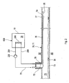
- FIG. 1 schematically shows a schematic diagram of an advantageous embodiment of an energy storage system 500 according to the invention with a storage tank device 600, which comprises a storage tank 10 with a first, second and third heat exchanger assembly 100, 200, 300, which are arranged in the housing of the storage tank 10.
- a first heat transfer medium 102 is used
- a second heat transfer medium 202 is used
- a third heat transfer medium 302 is used in the third heat exchanger arrangement 300 .
- the storage tank 10 contains as a storage medium 30, for example, water.
- the storage tank 10 is an environment-based storage tank 10, which is at least temporarily selectively heat exchange with the environment, ie at least temporarily, a heat flow from the environment in the storage tank 10 (or from this into the environment) for the function of the storage tank 10 is desired.
- the storage tank 10 is buried in the soil 50 in this embodiment, wherein the storage tank 10 is disposed near the surface.
- the reference numeral 52 is intended to indicate a system boundary in the soil surrounding the storage tank 10 50 and concerns an area in the soil 50, which can still enter much heat in the storage tank 10, ie a typical range of action between the environment of the storage tank 10 and the storage tank 10 itself, the typically depends on design parameters such as the size of the storage tank 10.
- the soil 50 may on the one hand serve as a source of geothermal energy and on the other hand deliver geothermal heat to the virtually uninsulated storage tank 10 in the usual withdrawal periods, such as heating periods.
- the surrounding soil 50 can at times even serve as an extension of the storage tank 10.
- the broken line indicates a typical area of action of the first heat exchanger assembly 100, with which energy is withdrawn from the storage tank 10, e.g. B. to operate a heat pump 60, which raises the heat removed from the storage tank 10 to a higher temperature level.
- This first heat exchanger assembly 100 operates with liquid as the heat transfer medium 102, such as brine or a glycol-water mixture or the like, which is circulated by a pump 120.
- the heat pump 60 may also be a heat pump system having a plurality of heat pumps.
- the heat pump 60 converts the relatively low temperature level of the storage medium 30 of the storage tank 10 to a higher temperature level and supplies, e.g. via a pump 112, one or more heat consumers 114, such as a building to be heated.
- the heat pump unit 60 may include an absorption heat pump and / or a compression heat pump and / or another type of heat pump.
- the second heat exchanger arrangement 200 serves to regenerate the storage medium 30 and supplies heat to the storage tank 10.
- the second heat exchanger assembly 200 may be temporarily used for cooling purposes, with sufficiently cooled storage medium 30 could be used as a source of cold.
- the energy storage system 500 may be operated in such optional phases as to allow cooling by the storage tank 10 even if the storage medium 30 has already completely melted away, e.g. in midsummer.
- the sensitive heat of the storage medium 30 can be used, resulting in the temperature change of the storage medium 30.
- the daytime temperature fluctuations can be used for cooling by z.
- the storage medium 30 e.g. by means of ambient air (heat exchanger arrangement 200) or e.g.
- the supply device 70 may include corresponding switching means and passes the corresponding heat transfer medium 202 to the connected "cold" consumers (not shown for the sake of simplicity). This type of use of daily temperature fluctuations with the help of the storage tank 10 is not possible with known energy storage systems.
- a gas is used, preferably air.
- the heat energy of the air ie the second heat transfer medium 202, is discharged directly to the storage medium 30 via the heat exchanger assembly 200. It is advantageous if the air has an increased humidity, since the energy input of moist air is particularly high compared to dry air because of the heat of condensation of auskondens Schlden in the cooling of the air in the heat exchanger assembly 200 water.
- Heat energy is introduced into the storage medium 30 of the storage tank 10 via the second heat exchanger arrangement 200, ie the storage tank 10 is charged.
- the second heat exchanger device 200 it is expedient if the second heat exchanger device 200 as possible has a large surface for heat exchange.
- a conveyor 220 such as a fan, a blower, a circulating pump or the like, is always arranged in the flow 204 of the heat exchanger assembly 200 during energy input, so that the waste heat of the conveyor 220 can be used with.
- a heat source 70 e.g. in the form of a heat supplying supply means 70 for a gaseous medium, e.g. Ambient air, connected to the heat input in the storage tank 10.
- the supply device 70 may in the simplest case have two open pipe ends, which are open to the environment for supply and exhaust air, or the return 206 has an open pipe end, while the feed 204 is connected to a device whose heat-supplying exhaust air through the second Heat exchanger assembly 200 is to be introduced into the storage tank 10.
- the supply device 70 can also comprise a (complex) supply and exhaust air system, optionally with control and / or regulation, or a heat source system with various connections for a wide variety of gas heat sources and exhaust gas routing (for example with air as the medium).
- connection option for a cooling system is conceivable, for. B. for a building cooling system that can be supplied with cool exhaust air from the second heat exchanger assembly 200, or with the heat from the exhaust air storage tank 10 can be supplied.
- the flow direction of the second heat transfer medium 202 in the second heat exchanger 200 can also be reversed.
- the supply device 70 different gas sources, in particular air sources, which provide the heat transfer medium 202 of the second heat exchanger arrangement 200 and between these different gas or air sources switch as needed.
- a gas or air source can be selected, which can deliver a particularly favorable energy input and be replaced by another gas or air source, if their energy input decreases and under a possible energy input of one or more other gas or air sources falls.
- Possible gas or air sources can be very diverse and simply coupled to the energy storage system 500 and the second heat exchanger assembly 200.
- ambient air can be used as the gas or air source, which offers the additional advantage of obtaining liquefaction heat of the water content of the air.
- flow 204 and / or the return 206 are partially relocated on the way to the storage tank 10 and away from the storage tank 10 over several meters in the ground 50 to additionally absorb geothermal heat.
- These areas of flow 204 and / or return 206 may also be switchable or be switched on and off by appropriate louvers or be bypassed by other lines.
- the third heat exchanger arrangement 300 serves to regenerate the storage medium 30 and to supply heat to the storage tank 10 and has a liquid heat transfer medium 302, for example a glycol-water mixture or brine, which is conveyed by a conveyor 320, eg a pump 320 is circulated.
- a liquid heat transfer medium 302 for example a glycol-water mixture or brine
- a conveyor 320 eg a pump 320 is circulated.
- heat energy for example of solar collectors, air brine absorbers, wastewater heat exchangers, rainwater or rainwater heat exchangers and the like
- the third heat exchanger assembly 300 is via a flow 304 and a Return 306 connected to the heat source 80, wherein the pump 320 is conveniently located in the flow 304.
- the flow direction can be reversed in certain operating phases, so that supply 304 serves as a return and return 306 as a flow.
- the heat source 80 may be an open collector 80, as shown in detail in FIGS FIGS. 7 and 8th is described.
- the third heat exchanger assembly 300 may also be divided into a plurality of units, each having its own terminals, or a plurality of third heat exchanger assemblies 300, e.g. be mounted one above the other.
- the serving as a storage medium 30 water is introduced directly into the storage tank 10, which contains a suitable amount of heat for heating the storage medium 30.
- the energy storage system 500 may be provided in series and / or in parallel.
- a single storage tank 10 may be coupled to two or more heat pumps 60, or multiple storage tanks 10 to a heat pump 60.
- the energy storage system 500 may be further developed to couple a storage tank 10 to a rainwater cistern for water exchange.
- the energy storage system 500 can be easily adapted to local requirements.
- FIG. 2 shows in a longitudinal section a favorable supply device 70 in the form of an air source 70 for a second heat exchanger arrangement 200 of an energy storage system 500, as shown in FIG FIG. 1 is described.
- the heat supplying air source 70 is in this case channel air 74 of a sewer 71, for example, a municipal sewer.
- the duct air 74 above the sewage 73 in the sewer 71 is very humid and relatively warm.
- the duct air 74 from the sewer 71 is sucked, for example at a manhole 72 via a suction opening 78 by means of a delivery device 220 and fed via a ring line 75 with flow 204 and return 206 of the second heat exchanger device 200 as a heat transfer medium and via a return port 79 back into the sewer 71st returned.
- the humidity contained in the channel air 74 of the sewer 71 condenses in the second heat exchanger device 200 in the storage tank 10 and can be pumped out and disposed of there, for example.
- the duct air 74 passes dried and cooled back into the sewer 71 back.
- the channel air 74 which is warmer than the storage tank 10, is used directly for the regeneration of the storage medium 30.
- a line section 76 is preferably laid over a longer path along the top of the sewer 71, which channels the channel air 74 sufficiently deep into the interior of the sewer 71.
- the return line 76 is preferably laid in the direction of the waste water flow (indicated by arrows 34).
- both the returning line section 76 and the suction line can be laid in different directions into the sewer 71, with the cold air line preferably being laid in the direction of a possibly present channel gradient.
- the manhole 72 may conveniently be sealed at its manhole cover, if due to the piping there is the danger that by local overpressure a leakage of duct air 74 is expected in the ambient air, especially in residential areas. However, this can be avoided by suitable design.
- the ends of the pipes laid in the sewer 71 may be protected by grids or similar devices against the ingress of rats or other animals and against foreign bodies.
- the end of the line section 76, which is located in the sewer 71 may be protected by a check valve 77, the channel air 74 can escape in the flow direction 35, but blocks the ingress of sewage 73, when flood in the sewer 71. Thus, e.g. Sludge deposits in the line section 76 are avoided.
- the check valve 77 can report a corresponding signal to a control unit via a switch, which then switches off the conveyor 220 in the loop 75 when the check valve 77 is closed.
- the duct air 74 from the sewer 71 can be used in conjunction with the second heat exchanger assembly 200 in the storage tank 10 in other ways.
- it may be an intake of air from the sewer 71, eg on the manhole cover, with passing through the second heat exchanger 200 in the storage tank 10 and venting the duct air 74 to the outside.
- the duct air 74, z. B. first passed through an odor filter and then released into the open.
- it may also be a suction of duct air 74th take place, however, for example, from a connecting line between a building and a (public) wastewater collection (sewer) and the channel air 74 are discharged back into the connecting line with or without odor filter.
- two further apart channel sections for the suction port 78 and return port 79 of the channel air 74 can be used in appropriate circumstances by the supply and removal of duct air 74 at far from each other remote locations of the same sewer 71 is made.
- pipes carrying duct air 74 to the storage tank 10 are laid in the ground 50, such as in FIG. 3 may be shown by way of example, they may additionally absorb geothermal heat or cache heat energy in the soil 50. When laying in the air, insulation of the heat-carrying leads to the storage tank 10 is useful.
- FIG. 3 shows a side view of an exemplary embodiment of a storage tank device 600 with a storage tank 10 in a mounting situation in the ground 50.
- the installation depth of the storage tank 10 is low, the storage tank 10 is disposed near the ground.
- a cylindrical neck 14 is formed with a smaller diameter, which can be opened eg for maintenance and inspection purposes.
- a groundwater contact of the storage tank 10 is not necessary for its function, however, a substrate with easily flowing groundwater on the regeneration of the storage medium 30 by the groundwater to the outside of the housing 12 heat supplied positively affect, since the memory content is usually colder than the groundwater is and groundwater flowing the storage tank 10 can continuously supply new heat.
- the housing 12 may be formed as a hollow body of any cross-section, for example in the form of a hollow cylinder or a cuboid.
- a favorable material for the housing is e.g. Stone, concrete or plastic.
- the housing 12 can expediently be designed so that it is passable or accessible.
- the size of the housing 12 may be adapted to the respective needs. For this purpose, for larger diameters of the housing 12, a support strut can also be arranged for static reasons, in order, e.g. to be able to carry a vehicle weight.
- the storage tank 10 may be formed in the manner of a rainwater cistern, e.g. poured in a concrete plant or made in a molding press made of plastic.
- Cross-section and shape of the storage tank 10 can be chosen arbitrarily, as just needed, such as a cylinder, cuboid, sphere or the like.
- the storage tank 10 can be delivered ready for installation including heat exchanger arrangements 100, 200, 300 to the installation site and only needs to be connected to the corresponding supply lines for the various heat transfer media, conveyors, heat sources, consumers, etc.
- a type of connection is shown, in which the flow 204 of the second heat exchanger device 200 is guided a distance in the ground 50, while the return line 206 is led upwards.
- other arrangements of flow 204 and return 206 may be provided, such as a central supply from above through the pipe 14th
- FIG. 4 shows a view of a cut-open storage tank 10 in a favorable embodiment with three heat exchanger assemblies 100, 200, 300.
- the first heat exchanger assembly 100 includes heat exchanger tubes 100W, preferably in the form of tube or hose windings.
- the heat exchanger tubes 100W may be formed substantially single-layer or multi-layered and stacked in axially spaced-apart planes 110 on top of each other.
- the material of the heat exchanger tubes 100W may be arbitrary, such as metal or plastic; Polyethylene (PE) is preferably used as inexpensive and durable material.
- the axially spaced-apart planes 110 can advantageously be flowed through in parallel from the heat transfer medium 102 in terms of flow technology by means of supply pipes 104, 106 acting as distributors or collectors. All levels 110 can be flowed through at the same time. Optionally, only a few selected ones of the levels 110 can be flowed through. By connecting the other levels 110, the storage tank 10 can briefly provide a significantly increased amount of heat available.
- the heat exchanger tubes 100W may preferably be wound in a U-shape as a double spiral per plane 110 on a spoke wheel-like mounting frame with the base of the double spiral centrally located and the two ends of the double spiral at the outer circumference of the plane 110 and the spoke wheel-like mounting frame, respectively. are led to a valve or line connection outside the storage tank 10.
- the risk of an explosive effect on the housing 12 during freezing of the storage medium 30 can be reduced if the heat exchanger tubes 100W are wound in each plane 110 so that a lesser distance is set in an inner, central area between the substantially concentric windings than in one Adjacent spiral arms are respectively flowed through in opposite directions of flow or rotation with the first heat transfer medium, which homogenizes the temperature in the storage medium 30.
- the planes 110 can analogously from bottom to top in increasing intervals be arranged.
- sufficient air space or a height range of storage medium 30 not intended for solidification can be provided so that the storage medium 30 can easily expand upon solidification.
- heat exchangers 100W can be arranged as flat spirals in each of these layers, or even be wound into one another, so that only two connections are required for a double layer or multiple layer of heat exchangers 100W.
- the housing 12 may be divided and dismountable with one or more mounting joints so as to be able to install individual or even a plurality of heat exchangers 100W in the housing 12 as prefabricated units.
- a removable cover 15 with a large area can be provided on the housing 12, which allows the heat exchanger 100W to be lowered into the housing.
- the second heat exchanger assembly 200 surrounds in this embodiment, the first heat exchanger assembly 100 in its axially upper region coaxial and z. B. at or near an inner side 18 of the housing 12 of the storage tank 10 is arranged.
- the second heat exchanger arrangement 200 consists of axially spaced tubes or hoses, in particular corrugated hoses, which serve as heat exchangers 200W and follow the contour of the inner side 18 of the housing 12. It is favorable to provide a gradient of the heat exchanger 200W between the feed 204 and the return 206 of the second heat exchanger arrangement 200 so that liquid condensing out in the heat transfer medium 202 can be collected and removed.
- the optional third heat exchanger arrangement 300 is arranged, which likewise surrounds the first heat exchanger arrangement 100 concentrically with wound and axially spaced tubes or tubes serving as heat exchangers 300W.
- the gas-working heat exchanger assembly 200 of the storage tank 10 typically does not have the same pipe diameter or dimensions of the respective heat exchangers 200W as the heat exchanger assemblies 100, 300 operated with liquid heat transfer media 102, 302, but is larger than these.
- the heat exchanger 200W z. B. have a significantly larger diameter than the liquid-carrying heat exchanger 100W, 300W.
- the heat exchangers 300W are preferably in the form of one or more turns of pipe (with a slope) running along the inside of the housing 18 as a screw curve, as in FIG FIG. 4 indicated.
- the arrangement of the heat exchangers 300W spaced from an inner wall is preferably such that the individual portions of the heat exchangers 300W have a slope in the same direction. A uniform gradient ensures that the simplest possible venting of the heat exchanger 300W during filling with the third heat transfer medium 302 is ensured.
- the second and third heat exchanger assembly 200 and 300 is preferably each housed in the late or not icing or solidifying zones of the storage medium 30 in the storage tank 10, but so that as little additional space is consumed. This results in a very compact storage tank 10.
- a round or cylindrical housing 12 is also used in a mounting position with horizontal rather than vertical axis as a storage tank 10, wherein the individual heat exchanger assemblies 100, 200 and 300 are then positioned rotated in space accordingly.
- the housing 12 made of plastic and two semi-cylindrical, larger basic shapes that form a horizontal Operaungsfuge in the assembled state, because then the empty upper half shell of the housing 12 from the top of the lower half-shell, with heat exchanger assemblies 100th , 200 and 300 can already be pre-assembled, can be lowered with a lifting device and combined with it to form a unit.
- the ice forms as a solid phase 108 gradually as so-called ice furs in a round shape around the heat exchanger 100W of the first heat exchanger assembly 100 in the liquid phase 109 of the storage medium 30, as in FIG. 5 is indicated.
- the heat exchanger assemblies 100 and 300 may be temporarily interconnected by switching means also to one unit, provided that they use the same heat transfer medium.
- the built in the storage tank 10 heat transfer devices of the heat exchanger assemblies 100, 200, 300 are disposed below a level 32 of the storage medium 30 and within the storage medium 30.
- the different heat exchanger arrangements 100, 200, 300 each act individually on the storage medium 30, but not directly from one heat exchanger arrangement 100, 200, 300 to another, but insofar only indirectly via the storage medium 30.
- the favorable arrangement of the heat exchanger assemblies 100, 200, 300 largely ensures that the volume of the solidified storage medium 30 growing upon discharge of the storage tank 10 is in its entirety as close as possible to certain maximum spatial limits, which in the FIG. 5 are indicated by solid and liquid phases 108 and 109 in approximately.
- the second and third heat exchanger assemblies 200 and 300 are located in a space region which is filled with liquid storage medium 30 in the ordinary case of operation.
- the total mass of the solidified storage medium 30 thus becomes In normal operation, as far as possible surrounded by an expansion pressure-protecting liquid portion 109, at least in the outer wall portion of the housing 12 and below the level 32.
- the second and third heat exchanger assembly 200 and 300 may be arranged differently in the storage tank 10 as desired.
- a plane 110 of the first heat exchanger assembly 100 may also be mounted directly on the bottom of the storage tank 10.
- the liquid fluids as the heat transfer medium 302 leading (minor) heat exchanger assembly 300 may be used as well as the gas-powered heat exchanger assemblies 200 at certain annual or operating times for cooling purposes.
- the housing 12 may also be thermally insulated, for. B. by attaching a Perimeterdämmung. In an insulated housing 12, hardly penetrates the geothermal, it is expedient that when energy is removed from the storage tank 10 always enough heat through the regeneration heat exchanger assemblies 200, 300 is entered into the storage tank 10 to excessive ice formation or excessive formation of solidified storage medium 30 to prevent.
- Connecting lines to the heat exchanger assemblies 100, 200, 300 may be performed at any point by the storage tank 10. These are expediently guided in such a way that the lowest possible heat or energy loss results and that no thermal short circuits occur between adjacent system components, which occurs, e.g. can be achieved by appropriate distances or insulation.
- FIGS. 6a and 6b show by way of example a plan view of a plane 110 of a first heat exchanger assembly 100 of a storage tank 10 according to the FIGS. 4 and 5 , with different arrangements of a coaxially surrounding second heat exchanger assembly 200, which is operated with the heat transfer medium 202.
- the heat exchangers 200W of the second heat exchanger assembly 200 are arranged like the first heat exchanger assembly 100 in axially spaced planes.
- Each heat exchanger 200W of the second heat exchanger assembly 200 in FIG Fig. 6a can also have more than one turn (eg 2 turns or 2.5 turns) or a fraction of one turn (eg 0.5 turns) ).
- the turns ratios of the second heat exchanger assembly 200 may be analogously applied to the perimeter of the packages, e.g. if they have a rectangular, square or polygonal floor plan.
- the heat exchangers 200W are preferably flexible for easy transport and for easy processing (eg flexible corrugated pipes or corrugated hoses), which can accordingly be laid adapted to the respective shape of a housing 12.
- a favorable turn length of a heat exchanger W200 of a second heat exchanger arrangement 200 between two connection pipes serving as flow 204 and return 206 is less than an inner circumference of the housing 12 when the heat exchangers 200W are laid close to the vertical housing wall.
- the heat exchanger 100W at this level 110 is in a spiral shape on a z. B. spokes wheel-like mounting frame, which is located around the inner region of the housing 12. Ports 107 for flow 104 and return 106 are arranged on the outer edge of the plane 110.
- the second heat exchanger arrangement 200 is arranged with tubular or tubular heat exchangers 200W, of which a heat exchanger 200W can be seen in a plane 110 in plan view, or one or more individual line sections 221 can be seen. Brackets and other details are omitted in the illustration for clarity.
- the individual heat exchangers 200W or their line sections 221 respectively encounter the feed 204 and return 206 formed as vertical connection pipes, which are arranged side by side in the storage tank 10 and larger in diameter than the heat exchanger 200W of the second Have heat exchanger assembly 200.
- the heat exchangers W200 meet in each level in flow 204 and return 206. Supply and exhaust air are led upwards in further lines or to the outside.
- the flow path of the heat transfer medium 202 in a plane corresponds almost to an inner circumference of the housing 12, so that between the flow 204 and return 206, a relatively large temperature spread can occur.
- the distributor 210 distributes the feed 204 of the heat transfer medium 202 into individual heat exchangers 200W and the collector 211 returns the individual flows 34 together into the return 206.
- FIG. 6b shows a variant in which the flow 204 and return 206 are diametrically opposed in the storage tank 10.
- the flow path of the heat transfer medium 202 corresponds to almost half an inner circumference of the housing 12, wherein the flow direction is rectified on each half inner circumference, so that between the flow 204 and return 206, a lower total flow resistance than in the embodiment in FIG. 6a which, for example, reduces the required delivery energy for the heat transfer medium 202.
- the second heat exchanger assembly 200 may have almost any alternative design, with a great deal of freedom.
- the connection tubes may be closely adjacent, spaced at a greater or lesser distance on the inner periphery of the housing, diametrically opposed, and the like.
- the specific embodiments can be selected, for example, according to a desired flow resistance in the second heat exchanger arrangement 200 and the like, and optimized for different purposes.
- the heat exchangers 200W are preferably designed with corrugated tubes or corrugated tubes, eg made of PE.
- the assembly may be along with one or more turns of the heat exchanger 200W near the housing wall, z. B. with only one turn as shown.
- Your buoyancy in the liquid Storage medium 30 can be intercepted by a fixture.
- the direction of flow 34 of the heat transfer medium 202 is indicated by arrows and preferably extends in the direction of a collection area for condensate 218, which is preferably located in the return line 206 serving as a collecting pipe. In such a collecting area or pump sump 218, the resulting condensate, usually condensed water, can then be removed by means of a pump.
- the condensate can, if necessary, ie at high condensate level, with the help of a level measuring device in conjunction with a switching device for switching on and off of a preferably electrically operated pump (not shown) are automatically pumped to the outside.
- the pump may for example be integrated into the collecting area 218 with an outwardly directed pressure line or arranged outside the collecting area 218 with a suction line guided into the collecting area 218.
- the heat exchangers 200W and other parts of the second heat exchanger assembly 200 are, for example, attached (directly) to the housing wall of the storage tank 10, as in FIG FIG. 4 illustrated, for example with the aid of mounting rails, which have clamping devices for the pipe diameter of the heat exchanger 200W or may be attached, for example, on the outside of a frame located inside the storage tank 10 frame construction.
- FIG. 7 shows an advantageous collector 80, which can serve as a supply device or heat source 80, in particular the third heat exchanger assembly 300.
- the collector 80 has a base that absorbs heat from the environment and from solar radiation.
- the collector 80 may include one or more levels 80a, 80b.
- two superimposed planes 80a, 80b are shown in which the lines 82a in one of the planes 80a are respectively offset from the lines 80b of the other plane 80b.
- a distributor region 86 is arranged on each side, wherein the lines 82a, 82b extend between the distributor regions 86.
- a medium flowing in the lines 82a and 82b, respectively, passes over the respective one Distributor area 86 in the adjacent lines 82a and 82b the same level 80a and 80b.
- a further distributor region 84a, 84b is arranged centrally.
- the central distributor region 84a, 84b for example, two holes 88 are arranged symmetrically to the center, which serve to fasten the collector 80. Due to the almost centric attachment of the collector 80 on a substrate, for example on a roof frame, a change in length of the lines 82a, 82b can be compensated in virtually all directions. The collector 80 requires no further attachment points and is virtually floating.
- the collector 80 is an open system, ie, preferably designed as plastic pipes or plastic hoses lines 82a, 82b of the collector 80 are exposed directly to the environment.
- the (liquid) heat transfer medium 302 may flow through the conduits 82a, 82b and absorb heat from the air or from solar radiation. This heat can eg by means of a circulation pump the storage tank 10 ( Fig. 1 ).
- the collector 80 is an absorber that converts sunlight into heat. In addition, heat is absorbed even without solar radiation, since the collector 80 is flowed through the coupling to the storage tank 10 for long periods with a medium (heat transfer medium 302) colder than the ambient air.
- the construction can be made entirely of plastic and inexpensive, for example, be produced by rotational molding.
- the collector 80 may be operated, for example, with a water / glycol mixture as a heat transfer medium, which circulates between the collector 80 and the heat exchanger assembly 300 in the storage tank 10.
- the circulating pump is preferably operated when in winter, the temperature of the storage tank 10 is lower than the temperature in the collector 80, which is approximately the Outside temperature corresponds. Should be cooled in the summer, the regeneration is prevented towards the end of the heating period, to prevent unwanted defrosting of the storage medium (eg ice).
- a particular advantage in the combination of the collector 80 with the storage tank 10 or storage tank device 600, in particular in the form of an ice storage, is the long duration of the regeneration of the storage medium 30 (FIG. FIG. 1 ). Even if the heat pump 60 ( FIG. 1 ) during the transitional period only a few hours a day in operation and the storage tank 10 extracts heat, the collector 80 can feed the heat of the environment in the storage tank 10 for 24 hours a day. This long run time (even at "night and fog") adds up to an extremely high energy density, which is significantly higher than that of the best vacuum tube collectors currently on the market.
- FIG. 8 shows in a sectional view through the collector 80, the cross section of the lines 82a, 82b, which have an oval cross section, wherein a vertical axis H82a of the cross section is greater than a transverse axis Q82a (only a cross section of the upper collector level 80a is denoted by reference numerals).
- the elliptical shape of the leads 82a, 82b maximizes their surface area, which is advantageous for the performance of the collector 80, since a high density of collector leads 82a, 82b can be accommodated in the base of the collector 80. According to the number of levels 80a, 80b, the effective collector surface can be increased while the base area remains the same.
- the lines 82a, 82b of the individual levels 80a, 80b can be mounted directly behind one another or offset from each other depending on the application, which allows the sun to show through to the lower level 80b.
- a cylindrical ice sheet can form around the conduits 82a, 82b, which to some extent does not form the next ice sheet touched. As with the storage tank device 600, this will avoid a decrease in the withdrawal rate even if ice is formed.
- the collector 80 can also be started up directly by means of a valve (not shown) by the heat pump, which up to an outside temperature of about 0 ° C sufficient extraction power for the heat pump 60 (FIG. FIG. 1 ) and thus relieves the storage tank 10. The energy of the storage tank 10 can thereby be "lifted” for colder temperatures.
- a storage tank 10 and an energy storage system 500 can be provided, with the energy in particular from air sources of any origin with only little Ummélzenergie in an otherwise.
- sol-powered latent storage can be introduced to allow widespread use of low-cost energy with relatively simple means.
Landscapes
- Engineering & Computer Science (AREA)
- Physics & Mathematics (AREA)
- Thermal Sciences (AREA)
- Mechanical Engineering (AREA)
- General Engineering & Computer Science (AREA)
- Chemical & Material Sciences (AREA)
- Combustion & Propulsion (AREA)
- Other Air-Conditioning Systems (AREA)
- Central Heating Systems (AREA)
Claims (15)
- Ensemble réservoir de stockage (600) pour un système d'accumulation d'énergie (500), comportant au moins un réservoir de stockage (10) comprenant un boîtier (12), contenant un milieu accumulateur (30) et au moins un premier agencement d'échangeur de chaleur (100) en contact avec le milieu accumulateur (30), le milieu accumulateur (30) présentant une transition de phase avec chaleur latente, l'au moins un premier agencement d'échangeur de chaleur (100) comprenant un premier milieu caloporteur (102), et un deuxième agencement d'échangeur de chaleur (200) comprenant un deuxième milieu caloporteur (202) et au moins un troisième agencement d'échangeur de chaleur (300) comprenant un troisième milieu caloporteur (302) étant disposés à l'intérieur du boîtier (12),- le premier agencement d'échangeur de chaleur (100) étant prévu pour, pendant une période d'extraction, extraire de la chaleur du milieu accumulateur (30) jusqu'à décharge thermique ;- le deuxième agencement d'échangeur de chaleur (200) et le troisième agencement d'échangeur de chaleur (300) étant prévus pour l'apport de chaleur dans le milieu accumulateur ; et- le premier agencement d'échangeur de chaleur (100) étant disposé centralement dans le boîtier (12) et comportant des plans (110) superposés axialement comprenant des tubes d'échangeur de chaleur (100W) disposés en forme de spirale, le deuxième agencement d'échangeur de chaleur (200) et le troisième agencement d'échangeur de chaleur (300) entourant le premier agencement d'échangeur de chaleur (100) et le deuxième agencement d'échangeur de chaleur (200) et/ou le troisième agencement d'échangeur de chaleur (300) étant disposés, au moins dans certaines régions, au niveau ou à proximité d'un côté intérieur (18) du boîtier (12) dans des zones du milieu accumulateur (30) se solidifiant tard ou pas du tout et/ou, au moins dans certaines régions, dans une paroi de boîtier.
- Ensemble réservoir de stockage selon la revendication 1, caractérisé en ce que le deuxième agencement d'échangeur de chaleur (200) est disposé, dans certaines régions, à l'intérieur du premier agencement d'échangeur de chaleur (100).
- Ensemble réservoir de stockage selon l'une quelconque des revendications précédentes, caractérisé en ce que le deuxième milieu caloporteur (202) est de l'air, en particulier de l'air ambiant et/ou de l'air d'évacuation de canal d'eaux usées et/ou de l'air d'évacuation de bâtiment, de manière particulièrement préférée de l'air chargé d'humidité.
- Ensemble réservoir de stockage selon l'une quelconque des revendications précédentes, caractérisé en ce qu'un dispositif de transport (220) est prévu dans une conduite d'alimentation (204) du deuxième agencement d'échangeur de chaleur (200).
- Ensemble réservoir de stockage selon l'une quelconque des revendications précédentes, caractérisé en ce que le boîtier (12) est prévu pour l'installation dans le sol (50), un échange de chaleur entre le boîtier (12) et le sol (50) étant autorisé de préférence au moins temporairement.
- Ensemble réservoir de stockage selon l'une quelconque des revendications précédentes, caractérisé par une configuration en tant que réservoir de stockage (10) transportable préfabriqué avec au moins un agencement d'échangeur de chaleur (100, 200, 300).
- Système d'accumulation d'énergie (500) comprenant un ensemble réservoir de stockage (600) selon l'une quelconque des revendications précédentes, un premier agencement d'échangeur de chaleur (100) du réservoir de stockage (10) étant accouplé à un premier circuit de milieux caloporteurs comprenant une unité de pompe à chaleur (60) et au moins un deuxième agencement d'échangeur de chaleur (200) du réservoir de stockage (10) étant accouplé à un deuxième circuit de milieux caloporteurs comprenant une source de chaleur (70) avec un milieu caloporteur gazeux (202), au moins un troisième agencement d'échangeur de chaleur (300) comprenant un troisième circuit de milieux caloporteurs étant prévu, caractérisé- en ce que les circuits de milieux caloporteurs des agencements d'échangeur de chaleur (100, 200, 300) sont désaccouplés les uns des autres du point de vue fluidique ;- en ce que le premier agencement d'échangeur de chaleur (100) est prévu pour, pendant une période d'extraction, extraire de la chaleur du milieu accumulateur (30) jusqu'à décharge thermique ;- en ce que le premier agencement d'échangeur de chaleur (100) est disposé centralement dans le boîtier (12) et comporte des plans (110) superposés axialement comprenant des tubes d'échangeur de chaleur (100W) disposés en forme de spirale ;- en ce que le deuxième agencement d'échangeur de chaleur (200) et le troisième agencement d'échangeur de chaleur (300) sont prévus pour l'apport de chaleur dans le milieu accumulateur ; et- en ce que le deuxième et/ou le troisième agencement d'échangeur de chaleur (200, 300) sont disposés au niveau ou à proximité d'un côté intérieur (18) du boîtier (12) dans des zones du milieu accumulateur (30) se solidifiant tard ou pas du tout et/ou, au moins dans certaines régions, dans une paroi de boîtier.
- Système d'accumulation d'énergie selon la revendication 7, caractérisé en ce qu'au moins l'un des premier et troisième milieux caloporteurs (102, 302) est liquide.
- Système d'accumulation d'énergie selon la revendication 7 ou 8, caractérisé en ce que le troisième agencement d'échangeur de chaleur (300) est accouplé à un collecteur (80) ouvert sur l'environnement.
- Système d'accumulation d'énergie selon la revendication 9, caractérisé en ce que le collecteur (80) comprend des conduites (82a, 82b) de section transversale ovale.
- Système d'accumulation d'énergie selon l'une quelconque des revendications 7 à 10, caractérisé en ce que le deuxième agencement d'échangeur de chaleur (200) est accouplé à un dispositif d'alimentation (70) et le troisième agencement d'échangeur de chaleur (300) est accouplé à une source de chaleur (80).
- Système d'accumulation d'énergie selon l'une quelconque des revendications 7 à 11, caractérisé en ce que le deuxième milieu caloporteur (202) est de l'air, en particulier de l'air ambiant et/ou de l'air d'évacuation de canal d'eaux usées et/ou de l'air d'évacuation de bâtiment, de manière particulièrement préférée de l'air chargé d'humidité.
- Système d'accumulation d'énergie selon l'une quelconque des revendications 7 à 12, caractérisé en ce que le deuxième agencement d'échangeur de chaleur (200) est accouplé à un canal d'eaux usées (72) par le biais d'une conduite annulaire (74), de l'air d'évacuation du canal d'eaux usées (72) pouvant être guidé à travers le deuxième agencement d'échangeur de chaleur (200) et pouvant être renvoyé dans le canal d'eaux usées (72).
- Procédé de fonctionnement d'un système d'accumulation d'énergie (500) selon l'une quelconque des revendications 7 à 13, le système d'accumulation d'énergie (500) comportant un ensemble réservoir de stockage (600) comprenant au moins un réservoir de stockage (10) comprenant un boîtier (12), contenant un milieu accumulateur (30) et au moins un premier agencement d'échangeur de chaleur (100) en contact avec le milieu accumulateur (30), le milieu accumulateur (30) présentant une transition de phase avec chaleur latente, l'au moins un premier agencement d'échangeur de chaleur (100) comprenant un premier milieu caloporteur (102), et un deuxième agencement d'échangeur de chaleur (200) comprenant un deuxième milieu caloporteur (202) et au moins un troisième agencement d'échangeur de chaleur (300) comprenant un troisième milieu caloporteur (302) étant disposés à l'intérieur du boîtier (12),
pendant une période d'extraction, de l'énergie thermique étant extraite du réservoir de stockage (10) par le biais du premier agencement d'échangeur de chaleur (100) jusqu'à décharge thermique et de l'énergie thermique étant acheminée par le biais du deuxième et/ou du troisième agencement d'échangeur de chaleur (200, 300), le deuxième et/ou le troisième agencement d'échangeur de chaleur (200, 300) étant disposés au niveau ou à proximité d'un côté intérieur (18) du boîtier (12) dans des zones du milieu accumulateur (30) se solidifiant tard ou pas du tout et/ou, au moins dans certaines régions, dans une paroi de boîtier, de telle sorte que de la chaleur à faible pouvoir calorifique soit acheminée temporairement, l'efficacité de l'ensemble réservoir de stockage augmentant lorsque la période d'extraction se déroule et que la température du milieu accumulateur (30) diminue. - Procédé selon la revendication 14, caractérisé en ce que le deuxième agencement d'échangeur de chaleur (200) fonctionne avec un milieu caloporteur gazeux (202) et le troisième agencement d'échangeur de chaleur (300) fonctionne avec un milieu caloporteur liquide (302).
Priority Applications (1)
| Application Number | Priority Date | Filing Date | Title |
|---|---|---|---|
| PL11757593T PL2614330T3 (pl) | 2010-09-10 | 2011-09-09 | Zbiornikowe urządzenie magazynujące do systemu magazynowania energii oraz system magazynowania energii ze zbiornikowym urządzeniem magazynującym |
Applications Claiming Priority (2)
| Application Number | Priority Date | Filing Date | Title |
|---|---|---|---|
| DE102010037474A DE102010037474A1 (de) | 2010-09-10 | 2010-09-10 | Speichertankeinrichtung für ein Energiespeichersystem sowie Energiespeichersystem mit einer Speichertankeinrichtung |
| PCT/EP2011/065656 WO2012032159A2 (fr) | 2010-09-10 | 2011-09-09 | Ensemble réservoir de stockage pour un système d'accumulation d'énergie et système d'accumulation d'énergie équipé d'un ensemble réservoir de stockage |
Publications (2)
| Publication Number | Publication Date |
|---|---|
| EP2614330A2 EP2614330A2 (fr) | 2013-07-17 |
| EP2614330B1 true EP2614330B1 (fr) | 2015-03-25 |
Family
ID=44651745
Family Applications (1)
| Application Number | Title | Priority Date | Filing Date |
|---|---|---|---|
| EP11757593.6A Active EP2614330B1 (fr) | 2010-09-10 | 2011-09-09 | Ensemble réservoir de stockage pour un système d'accumulation d'énergie et système d'accumulation d'énergie équipé d'un ensemble réservoir de stockage |
Country Status (6)
| Country | Link |
|---|---|
| EP (1) | EP2614330B1 (fr) |
| DE (1) | DE102010037474A1 (fr) |
| DK (1) | DK2614330T3 (fr) |
| ES (1) | ES2540591T3 (fr) |
| PL (1) | PL2614330T3 (fr) |
| WO (1) | WO2012032159A2 (fr) |
Cited By (2)
| Publication number | Priority date | Publication date | Assignee | Title |
|---|---|---|---|---|
| EP4392729A1 (fr) * | 2021-08-24 | 2024-07-03 | Sun-Ice Energy PTE. LTD. | Unite de chauffage et/ou de refroidissement a materiau a changement de phase |
| DE102024114783A1 (de) * | 2024-05-27 | 2025-11-27 | Max Bögl Wind AG | Wasserwärmetauscher sowie Energiespeicher |
Families Citing this family (20)
| Publication number | Priority date | Publication date | Assignee | Title |
|---|---|---|---|---|
| DE102011001273A1 (de) | 2011-03-15 | 2012-09-20 | Isocal Heizkühlsysteme Gmbh | Speichertank für ein Energiespeichersystem und Energiespeichersystem mit derartigen Speichertanks |
| PL2934272T3 (pl) * | 2012-12-20 | 2017-09-29 | Electrolux Home Products Corporation N.V. | Urządzenie gospodarstwa domowego i sposób działania urządzenia gospodarstwa domowego |
| DE102014000232A1 (de) * | 2014-01-09 | 2015-07-09 | Bertram Pelka | Variables regeneratives Energiesystem zum Heizen und Kühlen |
| AT516403B1 (de) | 2015-01-08 | 2016-05-15 | Masswohl Josef Dipl Ing Dr Techn | Verfahren zur Regeneration des Primärenergiespeichers einer Solewasserwärmepumpe |
| DE102015104909B3 (de) * | 2015-03-30 | 2016-09-29 | MBS Naturstromspeicher GmbH | Energiespeicher, Kraftwerksanlage mit Energiespeicher und Verfahren zum Betrieb desselben |
| DE102016002734A1 (de) * | 2016-03-05 | 2017-09-07 | Thomas Claus Kurz | Wärmetauscher für Zisternen und Gruben |
| DE102016108829A1 (de) | 2016-05-12 | 2017-11-16 | Laurens G. J. Wolters | Wärmespeicheranordnung |
| DE102016112784A1 (de) * | 2016-07-12 | 2018-01-18 | Viessmann Werke Gmbh & Co Kg | Kollektorfeld, Energieversorgungssystem mit einem Kollektorfeld sowie Verfahren zum Betreiben eines Energieversorgungssystems |
| DE102017204738A1 (de) * | 2017-03-21 | 2018-09-27 | BSH Hausgeräte GmbH | Wärmetauscher und damit ausgestattetes Kältegerät |
| DE102017112409A1 (de) | 2017-06-06 | 2018-12-06 | Viessmann Werke Gmbh & Co Kg | Latentwärmespeichersystem mit einem Latentwärmespeicher und Verfahren zum Betreiben eines Latentwärmespeichersystems |
| DE102017112407A1 (de) | 2017-06-06 | 2018-12-06 | Viessmann Werke Gmbh & Co Kg | Latentwärmespeichersystem mit einem Latentwärmespeicher und Verfahren zum Betreiben eines Latentwärmespeichersystems |
| US11585608B2 (en) | 2018-02-05 | 2023-02-21 | Emerson Climate Technologies, Inc. | Climate-control system having thermal storage tank |
| US11346583B2 (en) | 2018-06-27 | 2022-05-31 | Emerson Climate Technologies, Inc. | Climate-control system having vapor-injection compressors |
| DE102019111184B4 (de) * | 2019-02-26 | 2025-10-16 | caldoa GmbH | Kaltwärmenetz mit zwischengeschaltetem Latentwärmespeicher |
| DE102019121166B4 (de) * | 2019-08-06 | 2022-02-03 | caldoa GmbH | Modifiziertes Wärmeübertrager-Rohr für die Eisspeicheranwendung als Kältespeicher |
| EP3879201B1 (fr) * | 2020-03-11 | 2023-05-10 | Nikolai N. Korpan | Dispositif de stockage tampon souterrain ainsi que procédé de stockage tampon dans un support de moyen de stockage de chaleur |
| IT202100001091A1 (it) * | 2021-01-22 | 2022-07-22 | I Tes S R L | Batteria di accumulo termico a calore latente |
| PL243378B1 (pl) | 2021-10-31 | 2023-08-14 | Jerzy Jurasz | Instalacja do transportowania i magazynowania, zwłaszcza wodoru i jego mieszanek |
| DE102024112277A1 (de) * | 2024-05-02 | 2025-11-06 | caldoa GmbH | Eisspeicher und Verfahren zu dessen Montage |
| CH721935A1 (de) | 2024-06-27 | 2026-01-15 | Trinovent Gmbh | Anlage zur wärmeversorgung eines gebäudes und betriebsverfahren |
Citations (1)
| Publication number | Priority date | Publication date | Assignee | Title |
|---|---|---|---|---|
| US5944089A (en) * | 1994-05-26 | 1999-08-31 | Roland; Russel Anthony | Thermal storage systems for buildings |
Family Cites Families (13)
| Publication number | Priority date | Publication date | Assignee | Title |
|---|---|---|---|---|
| DE2931485A1 (de) * | 1979-08-03 | 1981-02-05 | Rudolf Oetjengerdes | Verfahren und vorrichtung zum gewinnen von heiz- und gebrauchswasserwaerme mittels kaeltemittelverdampfer im erdreich, in verbindung mit einer waermepumpenanlage |
| DE3004062A1 (de) * | 1980-02-05 | 1981-08-13 | Franz Karl 8500 Nürnberg Krieb | Ganzjaehrige heizung |
| DE3224854A1 (de) * | 1982-07-02 | 1984-01-05 | Corbelia GmbH, 5412 Puch | Waermespeicher |
| DE9014596U1 (de) * | 1990-10-22 | 1991-02-28 | Fabritz, Gerhard, 4150 Krefeld | Wärmetauscher |
| DE19807657C1 (de) * | 1998-02-24 | 1999-07-01 | Ivt Installations Und Verbindu | Wärmespeicher |
| DE102004052447A1 (de) | 2004-10-26 | 2006-04-27 | Alex Von Rohr | Energiespeicher, Wärmetauscheranordnung für einen Energiespeicher, Verfahren zum Betreiben eines Energiespeichers, Energiespeichersystem sowie Verfahren zum Betreiben eines Energiespeichersystems |
| JP2006234310A (ja) * | 2005-02-25 | 2006-09-07 | Osaka Gas Co Ltd | 蓄熱装置 |
| DE102005059942A1 (de) * | 2005-12-13 | 2007-06-14 | Georg Prinzing Gmbh & Co. Kg Betonformen- Und Maschinenfabrik | Verfahren zur Energiegewinnung aus Abwasserkanälen |
| DE202006005592U1 (de) * | 2006-04-04 | 2007-08-16 | Schröder, Ulrich | Wasserspeicher und Wärmepumpenanlage |
| DE102007006419A1 (de) * | 2007-02-05 | 2008-08-07 | Müller, Siegfried | Verfahren und Einrichtung zur Wärmerückgewinnung |
| DE102007026149B4 (de) * | 2007-06-04 | 2012-04-26 | Jürgen Gärtner | Pufferspeicher zur Speicherung von Wärmeenergie |
| WO2010014910A1 (fr) * | 2008-07-31 | 2010-02-04 | Walford Technologies, Inc | Système géothermique de chauffage, de ventilation et de refroidissement |
| DE102008041715A1 (de) * | 2008-08-29 | 2010-03-04 | Lüumel GmbH | Heiz- und Warmwassersystem für Gebäude |
-
2010
- 2010-09-10 DE DE102010037474A patent/DE102010037474A1/de not_active Ceased
-
2011
- 2011-09-09 WO PCT/EP2011/065656 patent/WO2012032159A2/fr not_active Ceased
- 2011-09-09 ES ES11757593.6T patent/ES2540591T3/es active Active
- 2011-09-09 PL PL11757593T patent/PL2614330T3/pl unknown
- 2011-09-09 DK DK11757593.6T patent/DK2614330T3/en active
- 2011-09-09 EP EP11757593.6A patent/EP2614330B1/fr active Active
Patent Citations (1)
| Publication number | Priority date | Publication date | Assignee | Title |
|---|---|---|---|---|
| US5944089A (en) * | 1994-05-26 | 1999-08-31 | Roland; Russel Anthony | Thermal storage systems for buildings |
Cited By (4)
| Publication number | Priority date | Publication date | Assignee | Title |
|---|---|---|---|---|
| EP4392729A1 (fr) * | 2021-08-24 | 2024-07-03 | Sun-Ice Energy PTE. LTD. | Unite de chauffage et/ou de refroidissement a materiau a changement de phase |
| EP4392729B1 (fr) * | 2021-08-24 | 2025-10-08 | Sun-Ice Energy PTE. LTD. | Unite de chauffage et/ou de refroidissement a materiau a changement de phase |
| DE102024114783A1 (de) * | 2024-05-27 | 2025-11-27 | Max Bögl Wind AG | Wasserwärmetauscher sowie Energiespeicher |
| EP4656997A1 (fr) | 2024-05-27 | 2025-12-03 | Max Boegl Wind AG | Échangeur de chaleur à eau et accumulateur d'énergie |
Also Published As
| Publication number | Publication date |
|---|---|
| WO2012032159A3 (fr) | 2012-06-28 |
| DK2614330T3 (en) | 2015-07-06 |
| DE102010037474A1 (de) | 2012-01-19 |
| ES2540591T3 (es) | 2015-07-10 |
| PL2614330T3 (pl) | 2015-11-30 |
| WO2012032159A2 (fr) | 2012-03-15 |
| EP2614330A2 (fr) | 2013-07-17 |
Similar Documents
| Publication | Publication Date | Title |
|---|---|---|
| EP2614330B1 (fr) | Ensemble réservoir de stockage pour un système d'accumulation d'énergie et système d'accumulation d'énergie équipé d'un ensemble réservoir de stockage | |
| EP2686633B1 (fr) | Accumulateur de chaleur latente et système de stockage d'energie avec un tel accumulateur | |
| EP1807672B1 (fr) | Accumulateur d'energie, systeme d'echange de chaleur d'un accumulateur d'energie, systeme d'accumulation d'energie et procede correspondants | |
| DE102008041715A1 (de) | Heiz- und Warmwassersystem für Gebäude | |
| DE2729635A1 (de) | Heizungs- und klimaausgleichssystem | |
| EP1740890A1 (fr) | Installation de chauffage et de traitement d'eau chaude | |
| DE202011003668U1 (de) | Pufferspeicher zur Aufnahme von flüssigem Medium, Wasserversorgungsanlage mit einem derartigen Pufferspeicher sowie Pufferspeichervorrichtung mit zumindest einem Pufferspeicher | |
| DE202011003667U1 (de) | Pufferspeicher zur Aufnahme von flüssigem Medium, Wasserversorgungsanlage mit einem derartigen Pufferspeicher sowie Pufferspeichervorrichtung mit zumindest einem Pufferspeicher | |
| EP2428760A2 (fr) | Réservoir de stockage terrestre pour un système de stockage d'énergie | |
| DE29801126U1 (de) | Solarenergieversorgte Heiz- und Warmwasseranlage für Gebäude | |
| DE2952541A1 (de) | Vorrichtung, insbesondere heizvorrichtung, zur ausnutzung von erdwaerme mit einer waermepumpe | |
| WO2015015244A1 (fr) | Système de gestion de la température | |
| EP2848885B1 (fr) | Accumulateur thermique | |
| AT518416B1 (de) | Wärmespeicher und Wärmeträgernetz | |
| GB1585528A (en) | Heating and air conditioning system | |
| DE202024102579U1 (de) | System zur Temperierung eines Gebäudes | |
| WO2016109861A2 (fr) | Procédé de régénération de l'accumulateur d'énergie primaire d'une pompe à chaleur à eau saumâtre | |
| AT516383B1 (de) | Fluidspeicher | |
| DE102009024498A1 (de) | Solarthermische Fernwärme mit Ferntransport in andere Klimazonen | |
| DE102011005231A1 (de) | Pufferspeicher zur Aufnahme von flüssigem Medium, Wasserversorgungsanlage mit einem derartigen Pufferspeicher, Pufferspeichervorrichtung mit zumindest einem Pufferspeicher sowie Verfahren zum thermischen Aufbereiten von flüssigem Medium für eine Wasserversorgungsanlage für ein Gebäude | |
| EP2198209A1 (fr) | Accumulateur géothermique avec barrière pare-vapeur, et procédé d'utilisation de la chaleur d'évaporation dans l'accumulateur géothermique | |
| DE102023132915B3 (de) | Kältespeicher und Verwendung eines solchen Kältespeichers als Energiespeicher in einem Gebäudeversorgungssystem | |
| EP0840074B1 (fr) | Structure constituée d'éléments préfabriqués | |
| DE3140120C2 (de) | Unterirdischer Mehrzweckschutzraum | |
| AT502567B1 (de) | Energieaustausch-einrichtung und deren nutzung |
Legal Events
| Date | Code | Title | Description |
|---|---|---|---|
| PUAI | Public reference made under article 153(3) epc to a published international application that has entered the european phase |
Free format text: ORIGINAL CODE: 0009012 |
|
| 17P | Request for examination filed |
Effective date: 20130410 |
|
| AK | Designated contracting states |
Kind code of ref document: A2 Designated state(s): AL AT BE BG CH CY CZ DE DK EE ES FI FR GB GR HR HU IE IS IT LI LT LU LV MC MK MT NL NO PL PT RO RS SE SI SK SM TR |
|
| DAX | Request for extension of the european patent (deleted) | ||
| RAP1 | Party data changed (applicant data changed or rights of an application transferred) |
Owner name: ISOCAL HEIZKUEHLSYSTEME GMBH |
|
| 17Q | First examination report despatched |
Effective date: 20140514 |
|
| GRAP | Despatch of communication of intention to grant a patent |
Free format text: ORIGINAL CODE: EPIDOSNIGR1 |
|
| INTG | Intention to grant announced |
Effective date: 20141024 |
|
| GRAS | Grant fee paid |
Free format text: ORIGINAL CODE: EPIDOSNIGR3 |
|
| GRAA | (expected) grant |
Free format text: ORIGINAL CODE: 0009210 |
|
| AK | Designated contracting states |
Kind code of ref document: B1 Designated state(s): AL AT BE BG CH CY CZ DE DK EE ES FI FR GB GR HR HU IE IS IT LI LT LU LV MC MK MT NL NO PL PT RO RS SE SI SK SM TR |
|
| RAP1 | Party data changed (applicant data changed or rights of an application transferred) |
Owner name: VIESSMANN EIS-ENERGIESPEICHER GMBH |
|
| REG | Reference to a national code |
Ref country code: GB Ref legal event code: FG4D Free format text: NOT ENGLISH |
|
| REG | Reference to a national code |
Ref country code: CH Ref legal event code: EP |
|
| REG | Reference to a national code |
Ref country code: IE Ref legal event code: FG4D Free format text: LANGUAGE OF EP DOCUMENT: GERMAN |
|
| REG | Reference to a national code |
Ref country code: DE Ref legal event code: R096 Ref document number: 502011006386 Country of ref document: DE Effective date: 20150507 |
|
| REG | Reference to a national code |
Ref country code: AT Ref legal event code: REF Ref document number: 718121 Country of ref document: AT Kind code of ref document: T Effective date: 20150515 |
|
| REG | Reference to a national code |
Ref country code: DK Ref legal event code: T3 Effective date: 20150630 |
|
| REG | Reference to a national code |
Ref country code: ES Ref legal event code: FG2A Ref document number: 2540591 Country of ref document: ES Kind code of ref document: T3 Effective date: 20150710 |
|
| REG | Reference to a national code |
Ref country code: NL Ref legal event code: T3 |
|
| PG25 | Lapsed in a contracting state [announced via postgrant information from national office to epo] |
Ref country code: FI Free format text: LAPSE BECAUSE OF FAILURE TO SUBMIT A TRANSLATION OF THE DESCRIPTION OR TO PAY THE FEE WITHIN THE PRESCRIBED TIME-LIMIT Effective date: 20150325 Ref country code: LT Free format text: LAPSE BECAUSE OF FAILURE TO SUBMIT A TRANSLATION OF THE DESCRIPTION OR TO PAY THE FEE WITHIN THE PRESCRIBED TIME-LIMIT Effective date: 20150325 Ref country code: SE Free format text: LAPSE BECAUSE OF FAILURE TO SUBMIT A TRANSLATION OF THE DESCRIPTION OR TO PAY THE FEE WITHIN THE PRESCRIBED TIME-LIMIT Effective date: 20150325 Ref country code: HR Free format text: LAPSE BECAUSE OF FAILURE TO SUBMIT A TRANSLATION OF THE DESCRIPTION OR TO PAY THE FEE WITHIN THE PRESCRIBED TIME-LIMIT Effective date: 20150325 |
|
| REG | Reference to a national code |
Ref country code: LT Ref legal event code: MG4D |
|
| PG25 | Lapsed in a contracting state [announced via postgrant information from national office to epo] |
Ref country code: LV Free format text: LAPSE BECAUSE OF FAILURE TO SUBMIT A TRANSLATION OF THE DESCRIPTION OR TO PAY THE FEE WITHIN THE PRESCRIBED TIME-LIMIT Effective date: 20150325 Ref country code: RS Free format text: LAPSE BECAUSE OF FAILURE TO SUBMIT A TRANSLATION OF THE DESCRIPTION OR TO PAY THE FEE WITHIN THE PRESCRIBED TIME-LIMIT Effective date: 20150325 Ref country code: GR Free format text: LAPSE BECAUSE OF FAILURE TO SUBMIT A TRANSLATION OF THE DESCRIPTION OR TO PAY THE FEE WITHIN THE PRESCRIBED TIME-LIMIT Effective date: 20150626 |
|
| PG25 | Lapsed in a contracting state [announced via postgrant information from national office to epo] |
Ref country code: EE Free format text: LAPSE BECAUSE OF FAILURE TO SUBMIT A TRANSLATION OF THE DESCRIPTION OR TO PAY THE FEE WITHIN THE PRESCRIBED TIME-LIMIT Effective date: 20150325 Ref country code: PT Free format text: LAPSE BECAUSE OF FAILURE TO SUBMIT A TRANSLATION OF THE DESCRIPTION OR TO PAY THE FEE WITHIN THE PRESCRIBED TIME-LIMIT Effective date: 20150727 Ref country code: SK Free format text: LAPSE BECAUSE OF FAILURE TO SUBMIT A TRANSLATION OF THE DESCRIPTION OR TO PAY THE FEE WITHIN THE PRESCRIBED TIME-LIMIT Effective date: 20150325 Ref country code: CZ Free format text: LAPSE BECAUSE OF FAILURE TO SUBMIT A TRANSLATION OF THE DESCRIPTION OR TO PAY THE FEE WITHIN THE PRESCRIBED TIME-LIMIT Effective date: 20150325 Ref country code: RO Free format text: LAPSE BECAUSE OF FAILURE TO SUBMIT A TRANSLATION OF THE DESCRIPTION OR TO PAY THE FEE WITHIN THE PRESCRIBED TIME-LIMIT Effective date: 20150325 |
|
| PG25 | Lapsed in a contracting state [announced via postgrant information from national office to epo] |
Ref country code: IS Free format text: LAPSE BECAUSE OF FAILURE TO SUBMIT A TRANSLATION OF THE DESCRIPTION OR TO PAY THE FEE WITHIN THE PRESCRIBED TIME-LIMIT Effective date: 20150725 |
|
| REG | Reference to a national code |
Ref country code: PL Ref legal event code: T3 |
|
| REG | Reference to a national code |
Ref country code: DE Ref legal event code: R097 Ref document number: 502011006386 Country of ref document: DE |
|
| PLBE | No opposition filed within time limit |
Free format text: ORIGINAL CODE: 0009261 |
|
| STAA | Information on the status of an ep patent application or granted ep patent |
Free format text: STATUS: NO OPPOSITION FILED WITHIN TIME LIMIT |
|
| 26N | No opposition filed |
Effective date: 20160105 |
|
| PG25 | Lapsed in a contracting state [announced via postgrant information from national office to epo] |
Ref country code: MC Free format text: LAPSE BECAUSE OF FAILURE TO SUBMIT A TRANSLATION OF THE DESCRIPTION OR TO PAY THE FEE WITHIN THE PRESCRIBED TIME-LIMIT Effective date: 20150325 |
|
| PG25 | Lapsed in a contracting state [announced via postgrant information from national office to epo] |
Ref country code: SI Free format text: LAPSE BECAUSE OF FAILURE TO SUBMIT A TRANSLATION OF THE DESCRIPTION OR TO PAY THE FEE WITHIN THE PRESCRIBED TIME-LIMIT Effective date: 20150325 |
|
| REG | Reference to a national code |
Ref country code: FR Ref legal event code: PLFP Year of fee payment: 6 |
|
| PG25 | Lapsed in a contracting state [announced via postgrant information from national office to epo] |
Ref country code: MT Free format text: LAPSE BECAUSE OF FAILURE TO SUBMIT A TRANSLATION OF THE DESCRIPTION OR TO PAY THE FEE WITHIN THE PRESCRIBED TIME-LIMIT Effective date: 20150325 |
|
| PG25 | Lapsed in a contracting state [announced via postgrant information from national office to epo] |
Ref country code: SM Free format text: LAPSE BECAUSE OF FAILURE TO SUBMIT A TRANSLATION OF THE DESCRIPTION OR TO PAY THE FEE WITHIN THE PRESCRIBED TIME-LIMIT Effective date: 20150325 Ref country code: BG Free format text: LAPSE BECAUSE OF FAILURE TO SUBMIT A TRANSLATION OF THE DESCRIPTION OR TO PAY THE FEE WITHIN THE PRESCRIBED TIME-LIMIT Effective date: 20150325 Ref country code: NO Free format text: LAPSE BECAUSE OF FAILURE TO SUBMIT A TRANSLATION OF THE DESCRIPTION OR TO PAY THE FEE WITHIN THE PRESCRIBED TIME-LIMIT Effective date: 20150625 Ref country code: HU Free format text: LAPSE BECAUSE OF FAILURE TO SUBMIT A TRANSLATION OF THE DESCRIPTION OR TO PAY THE FEE WITHIN THE PRESCRIBED TIME-LIMIT; INVALID AB INITIO Effective date: 20110909 |
|
| PG25 | Lapsed in a contracting state [announced via postgrant information from national office to epo] |
Ref country code: CY Free format text: LAPSE BECAUSE OF FAILURE TO SUBMIT A TRANSLATION OF THE DESCRIPTION OR TO PAY THE FEE WITHIN THE PRESCRIBED TIME-LIMIT Effective date: 20150325 |
|
| REG | Reference to a national code |
Ref country code: FR Ref legal event code: PLFP Year of fee payment: 7 |
|
| PG25 | Lapsed in a contracting state [announced via postgrant information from national office to epo] |
Ref country code: MK Free format text: LAPSE BECAUSE OF FAILURE TO SUBMIT A TRANSLATION OF THE DESCRIPTION OR TO PAY THE FEE WITHIN THE PRESCRIBED TIME-LIMIT Effective date: 20150325 |
|
| REG | Reference to a national code |
Ref country code: FR Ref legal event code: PLFP Year of fee payment: 8 |
|
| PG25 | Lapsed in a contracting state [announced via postgrant information from national office to epo] |
Ref country code: AL Free format text: LAPSE BECAUSE OF FAILURE TO SUBMIT A TRANSLATION OF THE DESCRIPTION OR TO PAY THE FEE WITHIN THE PRESCRIBED TIME-LIMIT Effective date: 20150325 |
|
| REG | Reference to a national code |
Ref country code: DE Ref legal event code: R082 Ref document number: 502011006386 Country of ref document: DE Representative=s name: RPK PATENTANWAELTE REINHARDT, POHLMANN UND KAU, DE Ref country code: DE Ref legal event code: R081 Ref document number: 502011006386 Country of ref document: DE Owner name: VIESSMANN CLIMATE SOLUTIONS SE, DE Free format text: FORMER OWNER: VIESSMANN EIS-ENERGIESPEICHER GMBH, 71636 LUDWIGSBURG, DE |
|
| REG | Reference to a national code |
Ref country code: ES Ref legal event code: PC2A Owner name: VIESSMANN CLIMATE SOLUTIONS SE Effective date: 20210527 |
|
| REG | Reference to a national code |
Ref country code: BE Ref legal event code: PD Owner name: VIESSMANN CLIMATE SOLUTIONS SE; DE Free format text: DETAILS ASSIGNMENT: CHANGE OF OWNER(S), MERGE; FORMER OWNER NAME: VIESSMANN HOLDING INTERNATIONAL GMBH Effective date: 20210510 |
|
| REG | Reference to a national code |
Ref country code: LU Ref legal event code: PD Owner name: VIESSMANN HOLDING INTERNATIONAL GMBH; DE Free format text: FORMER OWNER: VIESSMANN EIS-ENERGIESPEICHER GMBH Effective date: 20210603 Ref country code: LU Ref legal event code: PD Owner name: VIESSMANN CLIMATE SOLUTIONS SE; DE Free format text: FORMER OWNER: VIESSMANN HOLDING INTERNATIONAL GMBH Effective date: 20210603 |
|
| REG | Reference to a national code |
Ref country code: NL Ref legal event code: PD Owner name: VIESSMANN CLIMATE SOLUTIONS SE; DE Free format text: DETAILS ASSIGNMENT: CHANGE OF OWNER(S), MERGE; FORMER OWNER NAME: VIESSMANN HOLDING INTERNATIONAL GMBH Effective date: 20210713 |
|
| REG | Reference to a national code |
Ref country code: AT Ref legal event code: PC Ref document number: 718121 Country of ref document: AT Kind code of ref document: T Owner name: VIESSMANN CLIMATE SOLUTIONS SE, DE Effective date: 20210629 |
|
| REG | Reference to a national code |
Ref country code: GB Ref legal event code: 732E Free format text: REGISTERED BETWEEN 20210722 AND 20210728 |
|
| PGFP | Annual fee paid to national office [announced via postgrant information from national office to epo] |
Ref country code: TR Payment date: 20220822 Year of fee payment: 12 Ref country code: NL Payment date: 20220926 Year of fee payment: 12 Ref country code: LU Payment date: 20220926 Year of fee payment: 12 Ref country code: IE Payment date: 20220920 Year of fee payment: 12 Ref country code: GB Payment date: 20220920 Year of fee payment: 12 Ref country code: DK Payment date: 20220923 Year of fee payment: 12 Ref country code: AT Payment date: 20220920 Year of fee payment: 12 |
|
| PGFP | Annual fee paid to national office [announced via postgrant information from national office to epo] |
Ref country code: PL Payment date: 20220823 Year of fee payment: 12 Ref country code: FR Payment date: 20220926 Year of fee payment: 12 Ref country code: BE Payment date: 20220926 Year of fee payment: 12 |
|
| PGFP | Annual fee paid to national office [announced via postgrant information from national office to epo] |
Ref country code: IT Payment date: 20220921 Year of fee payment: 12 Ref country code: ES Payment date: 20221011 Year of fee payment: 12 |
|
| P01 | Opt-out of the competence of the unified patent court (upc) registered |
Effective date: 20230515 |
|
| PGFP | Annual fee paid to national office [announced via postgrant information from national office to epo] |
Ref country code: DE Payment date: 20230928 Year of fee payment: 13 |
|
| PGFP | Annual fee paid to national office [announced via postgrant information from national office to epo] |
Ref country code: CH Payment date: 20231001 Year of fee payment: 13 |
|
| REG | Reference to a national code |
Ref country code: DK Ref legal event code: EBP Effective date: 20230930 |
|
| REG | Reference to a national code |
Ref country code: NL Ref legal event code: MM Effective date: 20231001 |
|
| REG | Reference to a national code |
Ref country code: AT Ref legal event code: MM01 Ref document number: 718121 Country of ref document: AT Kind code of ref document: T Effective date: 20230909 |
|
| PG25 | Lapsed in a contracting state [announced via postgrant information from national office to epo] |
Ref country code: LU Free format text: LAPSE BECAUSE OF NON-PAYMENT OF DUE FEES Effective date: 20230909 |
|
| REG | Reference to a national code |
Ref country code: BE Ref legal event code: MM Effective date: 20230930 |
|
| GBPC | Gb: european patent ceased through non-payment of renewal fee |
Effective date: 20230909 |
|
| PG25 | Lapsed in a contracting state [announced via postgrant information from national office to epo] |
Ref country code: LU Free format text: LAPSE BECAUSE OF NON-PAYMENT OF DUE FEES Effective date: 20230909 |
|
| PG25 | Lapsed in a contracting state [announced via postgrant information from national office to epo] |
Ref country code: NL Free format text: LAPSE BECAUSE OF NON-PAYMENT OF DUE FEES Effective date: 20231001 |
|
| PG25 | Lapsed in a contracting state [announced via postgrant information from national office to epo] |
Ref country code: NL Free format text: LAPSE BECAUSE OF NON-PAYMENT OF DUE FEES Effective date: 20231001 |
|
| REG | Reference to a national code |
Ref country code: IE Ref legal event code: MM4A |
|
| PG25 | Lapsed in a contracting state [announced via postgrant information from national office to epo] |
Ref country code: IE Free format text: LAPSE BECAUSE OF NON-PAYMENT OF DUE FEES Effective date: 20230909 |
|
| PG25 | Lapsed in a contracting state [announced via postgrant information from national office to epo] |
Ref country code: GB Free format text: LAPSE BECAUSE OF NON-PAYMENT OF DUE FEES Effective date: 20230909 |
|
| PG25 | Lapsed in a contracting state [announced via postgrant information from national office to epo] |
Ref country code: AT Free format text: LAPSE BECAUSE OF NON-PAYMENT OF DUE FEES Effective date: 20230909 |
|
| PG25 | Lapsed in a contracting state [announced via postgrant information from national office to epo] |
Ref country code: IE Free format text: LAPSE BECAUSE OF NON-PAYMENT OF DUE FEES Effective date: 20230909 Ref country code: GB Free format text: LAPSE BECAUSE OF NON-PAYMENT OF DUE FEES Effective date: 20230909 Ref country code: FR Free format text: LAPSE BECAUSE OF NON-PAYMENT OF DUE FEES Effective date: 20230930 Ref country code: AT Free format text: LAPSE BECAUSE OF NON-PAYMENT OF DUE FEES Effective date: 20230909 |
|
| PG25 | Lapsed in a contracting state [announced via postgrant information from national office to epo] |
Ref country code: BE Free format text: LAPSE BECAUSE OF NON-PAYMENT OF DUE FEES Effective date: 20230930 |
|
| PG25 | Lapsed in a contracting state [announced via postgrant information from national office to epo] |
Ref country code: DK Free format text: LAPSE BECAUSE OF NON-PAYMENT OF DUE FEES Effective date: 20230930 |
|
| PG25 | Lapsed in a contracting state [announced via postgrant information from national office to epo] |
Ref country code: PL Free format text: LAPSE BECAUSE OF NON-PAYMENT OF DUE FEES Effective date: 20230909 |
|
| REG | Reference to a national code |
Ref country code: ES Ref legal event code: FD2A Effective date: 20241029 |
|
| PG25 | Lapsed in a contracting state [announced via postgrant information from national office to epo] |
Ref country code: PL Free format text: LAPSE BECAUSE OF NON-PAYMENT OF DUE FEES Effective date: 20230909 Ref country code: DK Free format text: LAPSE BECAUSE OF NON-PAYMENT OF DUE FEES Effective date: 20230930 |
|
| PG25 | Lapsed in a contracting state [announced via postgrant information from national office to epo] |
Ref country code: IT Free format text: LAPSE BECAUSE OF NON-PAYMENT OF DUE FEES Effective date: 20230909 |
|
| PG25 | Lapsed in a contracting state [announced via postgrant information from national office to epo] |
Ref country code: IT Free format text: LAPSE BECAUSE OF NON-PAYMENT OF DUE FEES Effective date: 20230909 |
|
| PG25 | Lapsed in a contracting state [announced via postgrant information from national office to epo] |
Ref country code: ES Free format text: LAPSE BECAUSE OF NON-PAYMENT OF DUE FEES Effective date: 20230910 |
|
| PG25 | Lapsed in a contracting state [announced via postgrant information from national office to epo] |
Ref country code: ES Free format text: LAPSE BECAUSE OF NON-PAYMENT OF DUE FEES Effective date: 20230910 |
|
| REG | Reference to a national code |
Ref country code: DE Ref legal event code: R119 Ref document number: 502011006386 Country of ref document: DE |
|
| REG | Reference to a national code |
Ref country code: CH Ref legal event code: PL |
|
| PG25 | Lapsed in a contracting state [announced via postgrant information from national office to epo] |
Ref country code: DE Free format text: LAPSE BECAUSE OF NON-PAYMENT OF DUE FEES Effective date: 20250401 |
|
| PG25 | Lapsed in a contracting state [announced via postgrant information from national office to epo] |
Ref country code: CH Free format text: LAPSE BECAUSE OF NON-PAYMENT OF DUE FEES Effective date: 20240930 |