EP2614880A9 - Dispositif a membrane pour la separation des fluids - Google Patents
Dispositif a membrane pour la separation des fluids Download PDFInfo
- Publication number
- EP2614880A9 EP2614880A9 EP13001864.1A EP13001864A EP2614880A9 EP 2614880 A9 EP2614880 A9 EP 2614880A9 EP 13001864 A EP13001864 A EP 13001864A EP 2614880 A9 EP2614880 A9 EP 2614880A9
- Authority
- EP
- European Patent Office
- Prior art keywords
- container
- flow medium
- housing
- separation
- separated
- Prior art date
- Legal status (The legal status is an assumption and is not a legal conclusion. Google has not performed a legal analysis and makes no representation as to the accuracy of the status listed.)
- Withdrawn
Links
- 239000012528 membrane Substances 0.000 title claims abstract description 45
- 238000001914 filtration Methods 0.000 title claims abstract description 5
- 239000012530 fluid Substances 0.000 title abstract description 12
- 238000000926 separation method Methods 0.000 claims abstract description 87
- 239000012466 permeate Substances 0.000 claims abstract description 23
- 239000012465 retentate Substances 0.000 claims abstract description 21
- 238000000108 ultra-filtration Methods 0.000 claims abstract description 4
- 238000007599 discharging Methods 0.000 claims abstract description 3
- 238000000034 method Methods 0.000 claims abstract description 3
- 238000001728 nano-filtration Methods 0.000 claims abstract description 3
- 238000001223 reverse osmosis Methods 0.000 claims abstract description 3
- 239000004033 plastic Substances 0.000 claims description 8
- 229920003023 plastic Polymers 0.000 claims description 8
- 229910000831 Steel Inorganic materials 0.000 claims description 7
- 239000010959 steel Substances 0.000 claims description 7
- 229910052751 metal Inorganic materials 0.000 claims description 5
- 239000002184 metal Substances 0.000 claims description 5
- RTAQQCXQSZGOHL-UHFFFAOYSA-N Titanium Chemical compound [Ti] RTAQQCXQSZGOHL-UHFFFAOYSA-N 0.000 claims description 4
- VNWKTOKETHGBQD-UHFFFAOYSA-N methane Chemical compound C VNWKTOKETHGBQD-UHFFFAOYSA-N 0.000 claims description 4
- 239000010936 titanium Substances 0.000 claims description 4
- 229910052719 titanium Inorganic materials 0.000 claims description 4
- 229920000049 Carbon (fiber) Polymers 0.000 claims description 3
- 239000011152 fibreglass Substances 0.000 claims description 3
- 239000004918 carbon fiber reinforced polymer Substances 0.000 claims description 2
- 239000000463 material Substances 0.000 claims description 2
- 238000011144 upstream manufacturing Methods 0.000 claims 1
- 238000004804 winding Methods 0.000 abstract description 3
- 238000009434 installation Methods 0.000 description 9
- 239000000203 mixture Substances 0.000 description 9
- 239000012510 hollow fiber Substances 0.000 description 8
- 210000001601 blood-air barrier Anatomy 0.000 description 5
- 238000013461 design Methods 0.000 description 4
- 238000012423 maintenance Methods 0.000 description 4
- 238000007789 sealing Methods 0.000 description 4
- 230000008901 benefit Effects 0.000 description 3
- 230000008439 repair process Effects 0.000 description 3
- XLYOFNOQVPJJNP-UHFFFAOYSA-N water Substances O XLYOFNOQVPJJNP-UHFFFAOYSA-N 0.000 description 3
- 229910052782 aluminium Inorganic materials 0.000 description 2
- XAGFODPZIPBFFR-UHFFFAOYSA-N aluminium Chemical compound [Al] XAGFODPZIPBFFR-UHFFFAOYSA-N 0.000 description 2
- 230000015572 biosynthetic process Effects 0.000 description 2
- 239000000470 constituent Substances 0.000 description 2
- 229930195733 hydrocarbon Natural products 0.000 description 2
- 150000002430 hydrocarbons Chemical class 0.000 description 2
- 239000007788 liquid Substances 0.000 description 2
- 239000013585 weight reducing agent Substances 0.000 description 2
- 229910000851 Alloy steel Inorganic materials 0.000 description 1
- 239000004215 Carbon black (E152) Substances 0.000 description 1
- 229920002430 Fibre-reinforced plastic Polymers 0.000 description 1
- 240000006829 Ficus sundaica Species 0.000 description 1
- 239000004917 carbon fiber Substances 0.000 description 1
- 230000008859 change Effects 0.000 description 1
- 238000005260 corrosion Methods 0.000 description 1
- 230000007797 corrosion Effects 0.000 description 1
- 230000035622 drinking Effects 0.000 description 1
- 239000011151 fibre-reinforced plastic Substances 0.000 description 1
- 239000000706 filtrate Substances 0.000 description 1
- 239000013505 freshwater Substances 0.000 description 1
- 239000008246 gaseous mixture Substances 0.000 description 1
- 239000003365 glass fiber Substances 0.000 description 1
- 239000011261 inert gas Substances 0.000 description 1
- 230000013011 mating Effects 0.000 description 1
- 230000004048 modification Effects 0.000 description 1
- 238000012986 modification Methods 0.000 description 1
- 239000003345 natural gas Substances 0.000 description 1
- 229920000642 polymer Polymers 0.000 description 1
- 229920005597 polymer membrane Polymers 0.000 description 1
- 239000013535 sea water Substances 0.000 description 1
- 239000000126 substance Substances 0.000 description 1
- 238000013022 venting Methods 0.000 description 1
Images

Classifications
-
- B—PERFORMING OPERATIONS; TRANSPORTING
- B01—PHYSICAL OR CHEMICAL PROCESSES OR APPARATUS IN GENERAL
- B01D—SEPARATION
- B01D63/00—Apparatus in general for separation processes using semi-permeable membranes
- B01D63/02—Hollow fibre modules
- B01D63/04—Hollow fibre modules comprising multiple hollow fibre assemblies
- B01D63/043—Hollow fibre modules comprising multiple hollow fibre assemblies with separate tube sheets
-
- B—PERFORMING OPERATIONS; TRANSPORTING
- B01—PHYSICAL OR CHEMICAL PROCESSES OR APPARATUS IN GENERAL
- B01D—SEPARATION
- B01D61/00—Processes of separation using semi-permeable membranes, e.g. dialysis, osmosis or ultrafiltration; Apparatus, accessories or auxiliary operations specially adapted therefor
- B01D61/14—Ultrafiltration; Microfiltration
- B01D61/145—Ultrafiltration
-
- B—PERFORMING OPERATIONS; TRANSPORTING
- B01—PHYSICAL OR CHEMICAL PROCESSES OR APPARATUS IN GENERAL
- B01D—SEPARATION
- B01D61/00—Processes of separation using semi-permeable membranes, e.g. dialysis, osmosis or ultrafiltration; Apparatus, accessories or auxiliary operations specially adapted therefor
- B01D61/02—Reverse osmosis; Hyperfiltration ; Nanofiltration
- B01D61/025—Reverse osmosis; Hyperfiltration
-
- B—PERFORMING OPERATIONS; TRANSPORTING
- B01—PHYSICAL OR CHEMICAL PROCESSES OR APPARATUS IN GENERAL
- B01D—SEPARATION
- B01D61/00—Processes of separation using semi-permeable membranes, e.g. dialysis, osmosis or ultrafiltration; Apparatus, accessories or auxiliary operations specially adapted therefor
- B01D61/02—Reverse osmosis; Hyperfiltration ; Nanofiltration
- B01D61/027—Nanofiltration
-
- B—PERFORMING OPERATIONS; TRANSPORTING
- B01—PHYSICAL OR CHEMICAL PROCESSES OR APPARATUS IN GENERAL
- B01D—SEPARATION
- B01D61/00—Processes of separation using semi-permeable membranes, e.g. dialysis, osmosis or ultrafiltration; Apparatus, accessories or auxiliary operations specially adapted therefor
- B01D61/58—Multistep processes
-
- B—PERFORMING OPERATIONS; TRANSPORTING
- B01—PHYSICAL OR CHEMICAL PROCESSES OR APPARATUS IN GENERAL
- B01D—SEPARATION
- B01D63/00—Apparatus in general for separation processes using semi-permeable membranes
- B01D63/06—Tubular membrane modules
-
- B—PERFORMING OPERATIONS; TRANSPORTING
- B01—PHYSICAL OR CHEMICAL PROCESSES OR APPARATUS IN GENERAL
- B01D—SEPARATION
- B01D65/00—Accessories or auxiliary operations, in general, for separation processes or apparatus using semi-permeable membranes
-
- B—PERFORMING OPERATIONS; TRANSPORTING
- B01—PHYSICAL OR CHEMICAL PROCESSES OR APPARATUS IN GENERAL
- B01D—SEPARATION
- B01D2313/00—Details relating to membrane modules or apparatus
- B01D2313/10—Specific supply elements
-
- B—PERFORMING OPERATIONS; TRANSPORTING
- B01—PHYSICAL OR CHEMICAL PROCESSES OR APPARATUS IN GENERAL
- B01D—SEPARATION
- B01D2313/00—Details relating to membrane modules or apparatus
- B01D2313/13—Specific connectors
-
- B—PERFORMING OPERATIONS; TRANSPORTING
- B01—PHYSICAL OR CHEMICAL PROCESSES OR APPARATUS IN GENERAL
- B01D—SEPARATION
- B01D2313/00—Details relating to membrane modules or apparatus
- B01D2313/20—Specific housing
- B01D2313/201—Closed housing, vessels or containers
- B01D2313/2011—Pressure vessels
-
- B—PERFORMING OPERATIONS; TRANSPORTING
- B01—PHYSICAL OR CHEMICAL PROCESSES OR APPARATUS IN GENERAL
- B01D—SEPARATION
- B01D2313/00—Details relating to membrane modules or apparatus
- B01D2313/20—Specific housing
- B01D2313/206—Specific housing characterised by the material
- B01D2313/2061—Organic, e.g. polymeric material
-
- B—PERFORMING OPERATIONS; TRANSPORTING
- B01—PHYSICAL OR CHEMICAL PROCESSES OR APPARATUS IN GENERAL
- B01D—SEPARATION
- B01D2313/00—Details relating to membrane modules or apparatus
- B01D2313/20—Specific housing
- B01D2313/206—Specific housing characterised by the material
- B01D2313/2062—Inorganic material
-
- B—PERFORMING OPERATIONS; TRANSPORTING
- B01—PHYSICAL OR CHEMICAL PROCESSES OR APPARATUS IN GENERAL
- B01D—SEPARATION
- B01D2319/00—Membrane assemblies within one housing
- B01D2319/02—Elements in series
- B01D2319/022—Reject series
Definitions
- the invention relates to a device for filtering and separating flow media by means of membranes, in particular by the method of ultrafiltration, reverse osmosis and nanofiltration, comprising a housing in which the membranes are arranged, an inlet for the guided into the device, to be separated flow medium and an outlet for discharging the permeate produced in the apparatus and an outlet for the retentate, which substantially forms a separation unit.
- Devices of this type are known in the most diverse embodiments in the prior art and are used for the most diverse separation tasks of the most diverse fluid mixtures in the industrial sector, on ships, on exploration platforms in the sea, on warships, in motor vehicles, in aircraft but also in the private sector, and always when the fluid mixtures are to be broken down into their constituents.
- Devices of the above mentioned type stationary but also on moving units such as ships and the like. Used when, for example, seawater should be desalinated to win fresh water as drinking or service water.
- devices of this type are also used in a stationary manner in order, for example, to separate seepage water, which arises in landfills, from the harmful mixture constituents in such a way that the produced pure water can safely be discharged into the environment.
- a very wide field of application of such devices is the separation of gaseous fluid mixtures, where an important area of application is the petrochemical, for example, from natural gas to separate the inert gas contained therein proportionally or from the gaseous mixture of air and gaseous hydrocarbons such as gasoline and Like.
- the gasoline liquefied Matute, such mixtures, for example.
- gasoline In large gasoline tanks or tanks above the gasoline liquid level arise, and it is the task to recover the gasoline content through the membrane separation.
- the membranes used for this purpose are generally polymer membranes, which are well known in the art, wherein for the particular desired separation task each have different suitable membranes are available that can fulfill the desired separation task.
- Devices of the type mentioned above are regularly installed independently of the type of medium or fluid mixture to be separated in successive and / or parallel arrangements in order to provide a sufficiently large membrane surface area for the respectively desired separation task.
- separation modules which must be interconnected with regard to the desired separation task. This requires planning and design a lot of work, since each device or each separation module must be connected to the other separation module, through elaborate pipe installations, not only for the medium to be separated, ie the fluid mixture, but also for the compiled permeate leaving and interconnected plurality of devices and the retentate also leaving the same.
- the permeate is also called filtrate.
- the invention in that a container is provided, in which at least two separation units are received in such a connected, that for the supply of the flow medium to be separated to both separation units, a common inlet is provided.
- the advantage of the solution according to the invention is that at least two separation units can be coupled together or connected to each other without installation of pipes, without separate pipe connections for the supply of the medium to be separated, ie of the fluid, also called "feed" in the art, are required ,
- the two separation units are merely introduced into the container and are coupled together with the pre-installed in the container connection means. This installation ensures that a pressure-tight connection between the inlet for the medium to be separated and from there to the two separation units is continuously possible.
- no installation effort is required for at least two separation units, with the result that the possibilities of the occurrence of leaks are drastically reduced and added that also a considerable weight reduction of the overall device over the known devices is achieved.
- the solution according to the invention enables applications of the device that hitherto due the highly reduced outer dimensions and weight were not possible, for example. On mobile units but also on maritime platforms, where is pungent to any additional weight, which applies equally to the space required for the device volume.
- the device according to the invention can itself in turn be interconnected in the manner of a modular principle with a plurality of devices according to the invention without great installation effort to large desired separation units, depending on the desired membrane total area.
- the membranes or membrane elements used for the specific separation task are used for such separation and filtering tasks for flow media or fluids.
- the membrane material to be used usually consisting of hydrocarbon-based polymers, but also on the nature of the membranes with respect to their mechanical structure.
- the device according to the invention it has proved to be advantageous for the device according to the invention to form the membranes as hollow fiber and / or capillary membranes, although in principle flat membranes, e.g. can be used in the form of membrane pads or in the form of spirally wound winding membranes.
- the container is designed such that the separation units are arranged substantially one behind the other on a container axis. This ensures that the supply of the medium to be separated to both separation units to a minimum lead is necessary for the medium to be separated or the fluid in the separation units inside.
- the inlet for the flow medium to be separated is arranged on the container in such a way that the flow medium can be conducted into both one separation unit and the other separation unit at the same time, virtually in the sense of introducing the medium to be separated via a quasi-T-shaped connection in the separation unit.
- the container itself may be formed substantially tubular, although in principle other embodiments are possible, for example. Such that the two separation units are arranged virtually side by side.
- the substantially tubular design of the container allows fast, safe installation of the separation units in the container itself, the separation units stabilize themselves in the container automatically, so that no costly attachment and alignment within the container for the separation units are needed, thereby reducing the cost and the repair and maintenance costs can be further reduced.
- the container has a substantially circular cross-section, ie it is advantageously designed as a substantially linear tube, so that the separation units to be introduced into the container actually stabilize and align themselves in series one behind the other.
- One behind the other does not mean that the separation units are connected in series with respect to their separation function or always must be, but only that they are mechanically arranged so that they are quasi one behind the other.
- an inlet for the flow medium to be separated is provided at substantially opposite locations of the container, i.
- the locations of the inlets based on the longitudinal extent of the container when it is, for example, tubular, positioned substantially centrally, so that can be increased by the double inlets of the total inlet cross section for the medium to be separated in the container in a simple manner in order to be able to increase the flow of the flow medium through the container in a simple manner in order to easily adapt to the respective desired higher separation efficiency.
- outlets for the permeate are advantageously formed at substantially opposite ends of the container, so that the necessary installation for the removal of the permeate can be kept low and also the container as a whole battery in the form of a plurality of containers in a correspondingly formed large separation unit can be used.
- the outlets themselves, provided with appropriate sealing means, inserted into receptacles, which may also have sealing means, without the need for additional installations.
- outlets for the retentate are formed in the region of substantially opposite ends substantially transversely of the container housing, which, provided with sealing means receptacles, which may also have sealing means and which are also arranged in a large separation unit, in a direction substantially transverse to Container housing can be inserted without it for the collection of the Container escaping retentate further installation needs.
- the invention has sought to reduce the total weight of the invention, which is advantageously achieved by forming the container made of plastic, and it is particularly advantageous to further reduce the weight of the plastic required for this with Carbon fibers or reinforced with glass fibers form.
- the plastic for the formation of the container has the advantage that it is substantially largely resistant to corrosion with respect to the medium to be separated or the fluid mixture, since liquid or gaseous, and is sufficiently dimensionally stable at low weight in the expected temperature range.
- the housing and / or the mutual closure elements of the separation unit made of metal, whereby the dimensional stability of the separation unit itself is sufficiently ensured
- at least the housing often called pressure tube
- the mutual closure elements also called end plates, are regularly made of aluminum.
- steel has very good strength properties
- both the housing of the separation units and the two-sided closure elements provided there as a rule have just been formed from steel. But steel is a considerable one has specific weight and counteracts the initially set goal in principle in certain cases, to form a device that is lighter than the known, it is gem. the invention advantageous to form at least the mutual closure elements made of titanium.
- the container housing is advantageously divisible into at least two container housing elements, which in turn can be connected to each other via connecting means, which In the form of mating or plug connections, it is particularly advantageous, however, to form the connection means on the container housing elements by means of threaded regions and / or recessed connections to be formed there. Threaded connections are self-centering and arresting, which is equally true for recessed joints, so that no additional means for fixing the two housing elements are necessary, which can be saved by the task weight and assembly and disassembly operations can be reduced to a minimum.
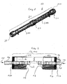
- Fig. 1 the container 20 of the device 10 is shown in a perspective view, wherein the container housing 31 is divided into two container housing elements 310, 311.
- a separation unit 11, 110 is received in the container housing elements 310, 311, wherein the separation units 11, 110 regularly have an identical structure, but solutions of the device 10 are also used conceivable in which the separation units 11, 110 have a different structure and each have different Trennspezifika respect.
- the separation units 11, 110 supplied flow medium 21, which is often called fluid or "feed" have.
- the basic structure of a separation unit 11, 110, as exemplified in Fig. 2 is well known, the in Fig. 2 shown separation unit 11, 110 is equipped with membranes 13 in the form of hollow fiber and / or capillary membranes.
- separation units 11, 110 which are to be accommodated in the container 20, can also be used with membranes in the form of cushion membranes or in the form of spirally wound winding membranes.
- the separation unit 11, 110 basically has a housing 12 which can withstand the pressures of the flow medium 15 within the housing and is usually made of plastic or fiber-reinforced plastic, but can also be made of steel, in the form of a steel tube.
- the housing closing elements 120, 121 are provided in a known per se, between which the hollow fiber or Kapillarmembranen 13 are clamped, s. Fig. 2 , Together with the housing 12, the closure elements 120, 121 which are suitably held at a distance from one another form a pressure-tight space in which the flow medium 15 to be separated flows.
- the housing 12 passes through a central tube 122, which has holes 123 distributed over the circumference, which traverse the wall of the tube 122. In this central tube 122, the permeate 17 is collected and discharged.
- the flow medium 15 flows through the hollow fibers, wherein the permeate 17 from the cavity through the walls of the hollow fiber membrane from the inside out.
- the flow medium 15 to be separated is led into the tube 122 and penetrates through the holes 123 into the interior of the housing 12, in which the membranes 13 are arranged.
- the flow medium 15 traverses, in a manner known per se, the walls of the membranes with respect to the mixture proportion in the flow medium 15, for which the membranes 13 are selective.
- the collected therein permeate 17 at one, possibly also at both ends of the housing 12 is collected (not shown here in detail), and is via an outlet 16 as permeate 17th discharged to the outside.
- the described separation unit 11 can be operated in a manner similar to that described above, depending on various types of membranes (hollow fiber membranes, capillary membranes, wound membranes, membrane pads). Depending on the various membrane types used, the supply of the flow medium 15 to be separated and the removal of permeate 17 and the retentate 19 in a modified manner, but this does not change the above-described separation principle of the flow medium 15 to be separated.
- the container 20 for receiving two separation units 11, 110 is shown.
- the container 20 consists essentially of a tubular body with a substantially circular inner cross section, so that the separation units 11, 110 can be accommodated guided therein, since the cross section of the separation units 11, 110 substantially corresponds to the inner cross section of the container 20.
- the container 20 comprises two substantially equal-sized container housing elements 310, 311, wherein at least one inlet 22 is provided for the flow medium 21 substantially in the middle between the two container housing elements 310, 311, wherein the flow medium 21 is the same as the flow medium 15 as described in connection with the description of the separation unit 11 above.
- the flow medium 21 flows via the inlet 22 into the inlet 14 of the respective separation units 11, 110.
- This is symbolically indicated by the arrows 15, 21 on both sides of the inlet 22 in FIG Fig. 3 shown.
- the connection between the inlet 22 of the container 20 and the respective separation units 11, 110 is ensured by appropriate structural design of both the inlet 14 of the separation units 11, 110 and by appropriate structural design of the inlet 22 within the container 20 so that a mechanically secure Connection and a pressure-tight connection between the inlet 22 and the inlet 14 is ensured.
- respective outlets 26, 260 are provided for the permeate 27 leaving the device 10 or the container 20, which is subjected to another use, if necessary a repeated separation, or is discharged and collected.
- the outlets 26, 260 are arranged concentrically to the imaginary container axis 23 passing through the container 20.
- each outlet 29, 290 for the device 10 leaving retentate 30 is provided, the retentate 30 either fed again to the separation circuit is collected or otherwise collected and used for any other purpose.
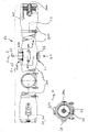
- the in the Fig. 5a to 5c illustrated device 10 comprises at its two ends 28, 280 of the container 20 each have an outlet 29, 290 for the retentate 30, such as previously described, which is equally applicable to the devices. the Fig. 6a to 6c applies.
- An outlet, 29 or 290, in another mode of operation of the device 10 may also serve as venting of the housing 22 of the separation unit 11 or separation units 11, 110 and / or of the container 20 or of the container housing.
- the outlets 29, 290 are closed.
- the so-called “cross-flow operation” the outlets 29, 290 are open for the removal of the retentate 30.
- the Fig. 5a to 5c at the location 24, 240 each have an inlet 22, 220 provided for the flow medium 21, and diametrically opposite to the container axis 23 in the radial direction.
- This embodiment of the device 10 is also in Fig. 3 and in Fig. 4 shown.
- the container 20 comprises at least two container housing elements 310, 311, which can be connected to the central portion of the container housing 31 via threaded connections and / or recesses (not shown).
- Such releasable connections allow the container housing 31 to be easily disassembled and assembled to provide, for example, quick access to those received therein Separating units 11, 110 to have, ie for repair and maintenance purposes but also for the basic initial assembly.
- the container housing 21 consists essentially of plastic, namely carbon fiber or glass fiber reinforced plastic, the former has the advantage of high strength with low weight.
- All the outlets 26, 260 for the permeate 27 and all the outlets 29, 290 for the retentate 30, as well as the inlets 22, 220 for the flow medium 21 to be separated, are constructed in such a way that they permit a fast, pressure-tight connection with other devices 20, if, for example, a plurality of devices are to be interconnected either in parallel or in series or both partially in parallel and partly in series in a separation unit or separation battery, not shown here.
Landscapes
- Chemical & Material Sciences (AREA)
- Chemical Kinetics & Catalysis (AREA)
- Engineering & Computer Science (AREA)
- Water Supply & Treatment (AREA)
- Nanotechnology (AREA)
- Separation Using Semi-Permeable Membranes (AREA)
Priority Applications (1)
| Application Number | Priority Date | Filing Date | Title |
|---|---|---|---|
| EP13001864.1A EP2614880A1 (fr) | 2011-08-15 | 2011-08-15 | Dispositif a membrane pour la separation des fluids |
Applications Claiming Priority (2)
| Application Number | Priority Date | Filing Date | Title |
|---|---|---|---|
| EP13001864.1A EP2614880A1 (fr) | 2011-08-15 | 2011-08-15 | Dispositif a membrane pour la separation des fluids |
| EP11006673.5A EP2559477B1 (fr) | 2011-08-15 | 2011-08-15 | Dispositif de filtrage et de séparation de supports d'écoulement avec des éléments à membranes à fibres creuses |
Related Parent Applications (1)
| Application Number | Title | Priority Date | Filing Date |
|---|---|---|---|
| EP11006673.5 Division | 2011-08-15 |
Publications (2)
| Publication Number | Publication Date |
|---|---|
| EP2614880A1 EP2614880A1 (fr) | 2013-07-17 |
| EP2614880A9 true EP2614880A9 (fr) | 2013-09-25 |
Family
ID=46210190
Family Applications (2)
| Application Number | Title | Priority Date | Filing Date |
|---|---|---|---|
| EP13001864.1A Withdrawn EP2614880A1 (fr) | 2011-08-15 | 2011-08-15 | Dispositif a membrane pour la separation des fluids |
| EP11006673.5A Active EP2559477B1 (fr) | 2011-08-15 | 2011-08-15 | Dispositif de filtrage et de séparation de supports d'écoulement avec des éléments à membranes à fibres creuses |
Family Applications After (1)
| Application Number | Title | Priority Date | Filing Date |
|---|---|---|---|
| EP11006673.5A Active EP2559477B1 (fr) | 2011-08-15 | 2011-08-15 | Dispositif de filtrage et de séparation de supports d'écoulement avec des éléments à membranes à fibres creuses |
Country Status (13)
| Country | Link |
|---|---|
| US (1) | US20130043178A1 (fr) |
| EP (2) | EP2614880A1 (fr) |
| JP (1) | JP2013039555A (fr) |
| KR (2) | KR20130018455A (fr) |
| CN (1) | CN102935332A (fr) |
| CA (1) | CA2751932A1 (fr) |
| DK (1) | DK2559477T3 (fr) |
| ES (1) | ES2415862T3 (fr) |
| IL (1) | IL226163A0 (fr) |
| MA (1) | MA34044B1 (fr) |
| SG (1) | SG190838A1 (fr) |
| TW (1) | TW201306922A (fr) |
| WO (1) | WO2013023711A1 (fr) |
Families Citing this family (6)
| Publication number | Priority date | Publication date | Assignee | Title |
|---|---|---|---|---|
| US8974668B2 (en) * | 2013-02-15 | 2015-03-10 | Maher Isaac Kelada | Hollow fiber membrane element and methods of making same |
| CN109052636B (zh) * | 2018-08-23 | 2021-07-13 | 浙江开创环保科技股份有限公司 | 一种卷式膜生物反应器 |
| US20200295386A1 (en) * | 2019-03-14 | 2020-09-17 | Honeywell International Inc. | Water exchanger for a fuel cell based power generator |
| EP3738664B1 (fr) * | 2019-05-15 | 2023-07-26 | R.T.S. ROCHEM Technical Services GmbH | Dispositif de filtrage et de séparation des mélanges liquides sous pression au moyen des membranes |
| DE102019115265A1 (de) * | 2019-06-06 | 2020-12-10 | membion Gmbh | Membranfilter |
| CN116282371B (zh) * | 2023-01-18 | 2025-10-03 | 珠海格力电器股份有限公司 | 一种具有级段式过滤功能的集成卷式膜滤芯和净水机 |
Family Cites Families (13)
| Publication number | Priority date | Publication date | Assignee | Title |
|---|---|---|---|---|
| US5137631A (en) * | 1991-10-22 | 1992-08-11 | E. I. Du Pont De Nemours And Company | Multiple bundle permeator |
| JP3900624B2 (ja) * | 1997-11-05 | 2007-04-04 | 栗田工業株式会社 | 膜分離装置 |
| US20020074277A1 (en) * | 2000-11-24 | 2002-06-20 | Membrane Concepts, S.L. | Filter assembly, system and method for filtering fluids |
| KR100354613B1 (ko) * | 2001-11-06 | 2002-10-11 | 박헌휘 | 교체 가능한 침지형 중공사막 모듈 |
| NL1019565C2 (nl) | 2001-12-14 | 2003-06-17 | Norit Membraan Tech Bv | Membraanfilterbehuizing en werkwijze welke deze toepast. |
| JP4369153B2 (ja) * | 2002-05-16 | 2009-11-18 | 株式会社神鋼環境ソリューション | 膜分離装置及び膜分離方法 |
| JP2004154659A (ja) * | 2002-11-06 | 2004-06-03 | Kubota Corp | 膜エレメントの再生方法 |
| US7063789B2 (en) * | 2003-08-13 | 2006-06-20 | Koch Membrane Systems, Inc. | Filtration element and method of constructing a filtration assembly |
| JP2005329393A (ja) * | 2004-04-22 | 2005-12-02 | Daicen Membrane Systems Ltd | 膜モジュール複合体を用いた濾過運転方法 |
| JP4531091B2 (ja) * | 2004-04-22 | 2010-08-25 | ベカルト プログレッシブ コンポジッツ,リミテッド ライアビリティー カンパニー | 円筒形ろ過カートリッジを保持する圧力容器 |
| EP1731214A1 (fr) * | 2005-06-06 | 2006-12-13 | Rochem RO-Wasserbehandlung GmbH | Elément d'espacement pour la conduction de fluides |
| JP4765913B2 (ja) * | 2006-11-29 | 2011-09-07 | 東洋紡績株式会社 | 皮膜つきノズルを有する逆浸透膜モジュール |
| GB0808464D0 (en) * | 2008-05-09 | 2008-06-18 | H2Oil & Gas Ltd | Filtration system |
-
2011
- 2011-08-15 EP EP13001864.1A patent/EP2614880A1/fr not_active Withdrawn
- 2011-08-15 EP EP11006673.5A patent/EP2559477B1/fr active Active
- 2011-08-15 ES ES11006673T patent/ES2415862T3/es active Active
- 2011-08-15 DK DK11006673.5T patent/DK2559477T3/da active
- 2011-09-09 KR KR1020110091559A patent/KR20130018455A/ko not_active Ceased
- 2011-09-09 CA CA2751932A patent/CA2751932A1/fr not_active Abandoned
- 2011-09-13 JP JP2011199262A patent/JP2013039555A/ja active Pending
- 2011-09-15 US US13/233,061 patent/US20130043178A1/en not_active Abandoned
- 2011-09-16 TW TW100133476A patent/TW201306922A/zh unknown
- 2011-10-11 CN CN2011103071236A patent/CN102935332A/zh active Pending
-
2012
- 2012-05-08 SG SG2013038732A patent/SG190838A1/en unknown
- 2012-05-08 WO PCT/EP2012/001971 patent/WO2013023711A1/fr not_active Ceased
- 2012-08-13 MA MA35150A patent/MA34044B1/fr unknown
-
2013
- 2013-05-05 IL IL226163A patent/IL226163A0/en unknown
- 2013-05-23 KR KR1020130058423A patent/KR20130060253A/ko not_active Ceased
Also Published As
| Publication number | Publication date |
|---|---|
| EP2559477B1 (fr) | 2013-05-22 |
| IL226163A0 (en) | 2013-06-27 |
| SG190838A1 (en) | 2013-07-31 |
| EP2614880A1 (fr) | 2013-07-17 |
| WO2013023711A1 (fr) | 2013-02-21 |
| KR20130060253A (ko) | 2013-06-07 |
| DK2559477T3 (da) | 2013-07-29 |
| ES2415862T3 (es) | 2013-07-29 |
| WO2013023711A9 (fr) | 2013-06-27 |
| CA2751932A1 (fr) | 2013-02-15 |
| JP2013039555A (ja) | 2013-02-28 |
| MA34044B1 (fr) | 2013-03-05 |
| CN102935332A (zh) | 2013-02-20 |
| US20130043178A1 (en) | 2013-02-21 |
| TW201306922A (zh) | 2013-02-16 |
| KR20130018455A (ko) | 2013-02-25 |
| EP2559477A1 (fr) | 2013-02-20 |
Similar Documents
| Publication | Publication Date | Title |
|---|---|---|
| EP2559477B1 (fr) | Dispositif de filtrage et de séparation de supports d'écoulement avec des éléments à membranes à fibres creuses | |
| DE10045227C1 (de) | Membranfilter für die Wasseraufbereitung | |
| DE60037356T2 (de) | Mantellose Hohlfasermembranvorrichtung | |
| DE69208099T2 (de) | Permeationsvorrichtung mit mehreren Bündeln. | |
| EP0947237B1 (fr) | Dispositif de séparation de milieux liquides chargés d'impuretés | |
| DE3317517C2 (de) | Vorrichtung zum Filtern und Trennen von flüssigen und gasförmigen Medien | |
| EP1268043B1 (fr) | Module de filtrage | |
| DE2525972C2 (de) | Membranelement und Vorrichtung zur Durchführung der Membranfiltration | |
| WO2017016913A1 (fr) | Cartouches à membranes pour la séparation de fluides pouvant être adaptées de manière flexible | |
| EP1147803B1 (fr) | Appareil de filtration et de séparation de fluides, notamment de fluides biologiques-organiques | |
| DE69005326T2 (de) | Verbindung für Membranelemente zur Fluidabtrennung. | |
| EP0891221A1 (fr) | Module d'une installation de separation par membrane, son utilisation et son procede de fabrication | |
| DE9005209U1 (de) | Rohrförmiges Filterelement | |
| EP3053640B1 (fr) | Tête de répartiteur modulaire pour corps de boîtier à membrane | |
| DE2945317C2 (de) | Vorrichtung zur Wasserentsalzung und -reinigung durch Umgekehrte Osmose und Ultrafiltration | |
| EP3738664B1 (fr) | Dispositif de filtrage et de séparation des mélanges liquides sous pression au moyen des membranes | |
| DE102011110126A1 (de) | Vorrichtung zum Filtern und Trennen von Strömungsmedien | |
| EP0394532A1 (fr) | Procédé et appareil de filtration de milieux liquides | |
| DE4039967A1 (de) | Anlage zur trennung von fluessigen oder gasfoermigen stoffgemischen | |
| DE202016100262U1 (de) | Filtrationsanlage | |
| DE102008025169B4 (de) | Filtermodul | |
| DE102016101000B4 (de) | Verfahren zur Filterung einer Flüssigkeit durch eine Filtrationsmembran sowie Filtrationsanlage | |
| DE202019002120U1 (de) | Vorrichtung zum Filtern und Trennen von unter Druck befindlichen liquiden Gemischen mittels Membranen | |
| EP3072575A1 (fr) | Module de membrane | |
| WO2014202663A1 (fr) | Conteneur de gaz comprenant plusieurs récipients de pression |
Legal Events
| Date | Code | Title | Description |
|---|---|---|---|
| PUAI | Public reference made under article 153(3) epc to a published international application that has entered the european phase |
Free format text: ORIGINAL CODE: 0009012 |
|
| 17P | Request for examination filed |
Effective date: 20130510 |
|
| AC | Divisional application: reference to earlier application |
Ref document number: 2559477 Country of ref document: EP Kind code of ref document: P |
|
| AK | Designated contracting states |
Kind code of ref document: A1 Designated state(s): AL AT BE BG CH CY CZ DE DK EE ES FI FR GB GR HR HU IE IS IT LI LT LU LV MC MK MT NL NO PL PT RO RS SE SI SK SM TR |
|
| AX | Request for extension of the european patent |
Extension state: BA ME |
|
| RIN1 | Information on inventor provided before grant (corrected) |
Inventor name: ARBEITER, UDO |
|
| 19U | Interruption of proceedings before grant |
Effective date: 20140201 |
|
| 19W | Proceedings resumed before grant after interruption of proceedings |
Effective date: 20140901 |
|
| STAA | Information on the status of an ep patent application or granted ep patent |
Free format text: STATUS: THE APPLICATION IS DEEMED TO BE WITHDRAWN |
|
| 18D | Application deemed to be withdrawn |
Effective date: 20140118 |