EP2614924A1 - Tenaille réglable autobloquante - Google Patents
Tenaille réglable autobloquante Download PDFInfo
- Publication number
- EP2614924A1 EP2614924A1 EP11823109.1A EP11823109A EP2614924A1 EP 2614924 A1 EP2614924 A1 EP 2614924A1 EP 11823109 A EP11823109 A EP 11823109A EP 2614924 A1 EP2614924 A1 EP 2614924A1
- Authority
- EP
- European Patent Office
- Prior art keywords
- locking pliers
- adjustable self
- spindle
- fixed handle
- pliers according
- Prior art date
- Legal status (The legal status is an assumption and is not a legal conclusion. Google has not performed a legal analysis and makes no representation as to the accuracy of the status listed.)
- Withdrawn
Links
Images



Classifications
-
- B—PERFORMING OPERATIONS; TRANSPORTING
- B25—HAND TOOLS; PORTABLE POWER-DRIVEN TOOLS; MANIPULATORS
- B25B—TOOLS OR BENCH DEVICES NOT OTHERWISE PROVIDED FOR, FOR FASTENING, CONNECTING, DISENGAGING, OR HOLDING
- B25B7/00—Pliers; Other hand-held gripping tools with jaws on pivoted limbs; Details applicable generally to pivoted-limb hand tools
- B25B7/12—Pliers; Other hand-held gripping tools with jaws on pivoted limbs; Details applicable generally to pivoted-limb hand tools involving special transmission means between the handles and the jaws, e.g. toggle levers, gears
- B25B7/123—Pliers; Other hand-held gripping tools with jaws on pivoted limbs; Details applicable generally to pivoted-limb hand tools involving special transmission means between the handles and the jaws, e.g. toggle levers, gears with self-locking toggle levers
Definitions
- the present invention refers to adjustable self-locking pliers wherein the structural and ergonomic characteristics aids the user in the handling thereof and the regulation of its opening, reducing the efforts to be applied in such regulation and providing a protection of the threads of the spindle against bumps or welding projections.
- the adjustable pliers work so as to tighten different thicknesses of objects by varying the positions geometry of points A - B - C - D, hinges that make up the kinematic chain of the system.
- these hinge points form a hinged quadrilateral so that the sides of said quadrilateral comprise:
- the quadrilateral is transformed into a triangle by aligning three of its hinge points B-C-D.
- the adjustment for different thicknesses of objects is obtained by varying the length of some sides of the quadrilateral, in this case by varying the side DA.
- adjustable pliers The most common way to control the opening of adjustable pliers is performed by turning a knob of a screw that is housed in the rear of the pliers fixed handle and which moves axially away from the fixed handle while increasing the thickness of the object to be grasped and, therefore, the necessary separation between the jaws of the pliers.
- control consists of rotating a nut located in the central area of the fixed handle, which axial movement is immobilized by the handle itself, said nut displacing a spindle which is immobilized with the connected connecting rod.
- the invention patent with publication number in Spain ES2125757 employs a control system operated by a knob that moves away from the fixed handle, which spins a spindle on which a staple is moved, which is guided in a number of openings made on the fixed handle, the back of the connecting rod being hinged on said staple.
- the problem of such system lies, on the one hand, in that said openings leave the grooving of the spindle unprotected against the entry of impurities, bumps, etc., which may affect the control of the pliers.
- Such patent protects a system for turning the adjustable pliers into a pliers wrench; said system is based on a movable slider located in the fixed handle and a pointed screw protruding from the release cam, in such a way that in the position of the slider functioning as pliers wrench the screw abuts the same avoiding the blockage.
- the adjustable pliers have a spring between the fixed jaw or the fixed handle and the movable jaw, which helps to open such pliers when unlocked, exerting its maximum pulling when the pliers are adjusted for a minimum thickness with the disadvantage that the spring force is reduced when the thickness of the work piece to be held increases, resulting when the thickness is maximum in a lack of force.
- patent WO 9937445 which incorporates a screw having an integral knob, a spring anchored to a fixed point, a carriage encapsulated into the fixed handle by flanges bent at the extremities of the wings of said handle and with a non-detachable hinge from the connecting rod in position coaxial with the spindle.
- the invention provides adjustable self-locking pliers provided with a fixed handle, to which a fixed jaw in turn complemented with a movable jaw is jointly connected.
- This movable jaw is hinged to the fixed handle and, through its other end to a movable handle, with the movable handle being connected to the front end of a connecting rod that, at its rear end and through a cross pin, is connected to and supported on a mechanism for adjusting the distance between the opposed dentations of both jaws.
- the invention is characterized in that the adjustment mechanism comprises a spindle disposed along a longitudinal inner cavity of the fixed handle, while it is axially retained in both directions, said spindle being connected to a nut carriage guided along said longitudinal inner cavity without rotational movement, said nut carriage being connected to the connecting rod at its rear end by a rear hinge pin.
- the longitudinal inner cavity of the fixed handle includes a dome-shaped arched bottom on which the upper curve-convex part of the nut carriage is complementarily supported.
- the spindle is supported, by a forward portion thereof, on the upper pin attached to the fixed handle, such forward portion being determined by a diametric narrowing.
- the hinge between the connecting rod and the nut is interchangeably produced in a male-female or a female-male configuration, on a transverse axis offset with respect to the longitudinal axis of the spindle discharging and spreading without any problem all eccentric loads on the spindle itself and over a large area at the bottom of the fixed handle.
- the nut carriage includes an open housing with a lower support having a single or double seat, in the bottom of which the rear pin of the connecting rod is coupled being removable in the hinge.
- the spindle receives the longitudinal load through the nut, transmitting it to the fixed handle through a large diameter section in an area of maximum strength of its rear wall, thus improving the load distribution, since in most existing models the load is only received by the tip of the narrow section of the spindle.
- the pliers comprise a spring connected to two movable elements, the movable jaw and the nut carriage, which move in the same direction, thus eliminating the problem of reducing the force for opening the jaws.
- the spindle is axially retained in an outward direction in a rear wall of the fixed handle, said rear wall being provided with a through hole, through which a terminal section of such spindle protrudes outwardly, said spindle having an annular shoulder abutting against the inner face of the mentioned rear wall of said fixed handle acting as an axial retention means in the outward direction of said spindle, as mentioned above, and as a strength support for unloading efforts.
- Said annular shoulder can be replaced by a flat or elastic washer that collects the spindle trust and supplies it into the wall of the fixed handle, which may simultaneously serve in its case, as an elastic spring for releasing the stiffness in the lock.
- the pliers are also characterized in that they comprise a knob coupled to the end portion of the spindle, the knob having an axial hole into which the said end portion of the spindle is embedded.
- the coupling between the end portion of the spindle and the axial hole of the knob, comprises relative anti-rotation means between both elements determined by flat areas complemented to each other.
- Another feature of the invention is that by decoupling said knob the whole adjusting mechanism can be removed.
- the invention incorporates a converter hinged to the release cam with a transverse pin that remains locked in two positions.
- a converter hinged to the release cam with a transverse pin that remains locked in two positions.
- oscillating by a simple twist with a finger until it rests on the area of the cam making contact with the connecting rod and interposed between the support of both, thereby preventing the locking in all adjustment positions, allowing the operation of the tool as a pliers wrench whilst remaining ergonomic for grasping work pieces of large thickness, which is impossible with a universal pliers wrench.
- release cam always made of metal in this type of pliers, attached into the movable handle therein by the pressure of a spring, is made of a resistant plastic material and carries a small tempered steel plate inserted in the area making contact with the connecting rod for higher specific resistance to compression and friction.
- another feature of the invention is that there are arranged two separate plastic linings covering the two handles so as to provide a better contact with increased comfort and in such a way that given the dielectric characteristics of the linings, the knob and the release cam can they insulate the hand from a household voltage.
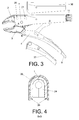
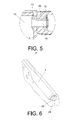
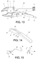
- the adjustable self-locking pliers comprise a fixed handle 1, the inner space of which serves as a guiding system for a nut carriage 9, said guidance system being correspondent with the arc-shaped nut 9 in its upper arched surface with the dome-shaped bottom having the fixed handle therein.
- the nut carriage 9 is axially moved on a spindle 10 thanks to the guidance system, which prevents rotating the nut carriage 9 on the spindle 10, when the same is rotated through a knob 11.
- This knob 11 is kept in an unchanged position with respect to the fixed handle 1 and, it is attached to spindle 10, either by threading or by a retention washer 18.
- both the spindle 10 at its end part and the knob 11 have a male-female coupling with two or more flat faces 13-14 in parallel or opposed to each other.
- the spindle 10 is embedded in the end where the knob 11 is located and at the opposite end it is supported on an upper pin 12, so that this support, on the one hand provides a reduction of the momentum and efforts in the embedding, thus prolonging the life of the tool and facilitating the opening thereof for large thicknesses and, on the other hand, avoids the bending of the opposite end of the spindle 10 when the nut carriage 9 gets close to that position.
- the forward portion of the pin 10 resting on the upper spindle 12 comprises a diametric narrowing 23.
- these pliers have a spring 5 anchored to the movable jaw 3 and to the nut carriage 9, instead of between the movable and fixed jaws or between the moveable jaw and the fixed handle as in traditional pliers, so that this arrangement of the spring 5 increases its tensile strength as the adjustment of the thickness of the object to be held with the pliers is increased, resulting in an appropriate and sufficient grasp in all the adjustment positions.
- the movable jaw 3 is supplemented with a fixed jaw 2 attached to the fixed handle 1 through pins 20 and 21.
- the nut carriage 9 is associated to one end of a connecting rod 6-6' by a rear hinge pin 7, which hinges the connecting rod 6-6' and the nut carriage 9 thanks to the shape of said nut carriage 9 on its underside.
- the connecting rod 6-6' is connected at its opposite end to the movable handle 4 through a front hinge pin 17.
- the rear hinge pin 7 of the nut carriage 9 is a cylindrical support of such rear pin 7 on the mentioned cradle, which enhances the discharge of forces and thus allows and makes the assembly and disassembling, cleaning and maintaining thereof easier, as well as also making the replacement of the spring 5 easier.
- the fixed handle 1 is complemented by the movable handle 4 to which a release cam 8 is connected, while said movable handle 4 is connected to the movable jaw 3 through a lower hinge pin 16, with the movable jaw 3 being coupled to the fixed handle 1 through a centre hinge pin 15.
- the nut carriage 9 has an open lower bearing housing 19, at the bottom of which the rear hinge pin 7 connecting the 6-6' to the mentioned nut carriage 9 is hinged.
- the open lower support housing 19 comprises a structure by way of male element that is located between a pair of wings 44 forming part of the connecting rod 6'.
- the open lower support housing 19 comprises a structure by way of female element receiving an end portion of the connecting rod (6).
- the spring 5 is connected through a front end thereof into a hole 42 of the movable jaw 3, while the rear end of such spring 5 is connected to a bore 22 provided in a area ahead of the nut carriage 9.
- Such hole 42 is located between the hinge of the centre hinge pin 15 and the lower hinge pin 16.
- the spindle 10 is outwardly retained in an axial direction in a rear wall 24 of the fixed handle 1, said rear wall 24 is provided with a through hole 25 through which an terminal section 26 of such spindle 10 outwardly protrudes, such spindle 10 having an annular shoulder 27 abutting against the inner face of the rear wall 24 of the fixed handle 1 as an axial retention means in the outward direction of the mentioned spindle.
- Said annular shoulder 27 can be replaced by an elastic flat washer 43.
- the knob 11 is coupled to the terminal section 26 of the spindle 10, while said knob has an axial hole 28 into which said terminal section 26 of the spindle 10 is embedded, the axial retention being performed in the inward direction of the mentioned spindle.
- the coupling between the terminal section 26 of the spindle 10 and the axial hole 28 of the knob 11 comprises anti-rotation means determined by the male-female coupling corresponding with the flat faces 13-14 mentioned above.
- the release cam 8 is attached under pressure to the movable handle 4 in its interior by means of a spring 41 arranged in correspondence with opposed hinge holes 30 of the release cam 8 connected to the movable handle 4.
- Said release cam has a body 39, preferably made of resistant plastic material that can be made of other materials, said body 39 including a small tempered steel sheet 40 in the area making contact with the connecting rod 6-6' for further specific resistance to compression and friction.
- the body 39 has also a hinge hole 31 and locking holes 33 and 34 arranged on both sides of said hinge hole 31.
- the release cam 8 has a swivel converter 29 hinged into the hinge hole 31, which in one position leaves some appendages 32 embedded into the locking holes 33 of the cam 8, thus the converter 29 remaining retracted into the recess thereof.
- Such appendages 32 are symmetric and convex.
- Such wedge 35 is configured by a metal plate having one or more folds, also performing in addition to its function of preventing the blockage, a spring-effect function facilitating the opening between the handles.
- adjustable pliers can have some plastic material linings 36 and 37, covering the metal surface of the fixed 1 and movable 4 handles, the inner forms of which adjust to the outer forms of their respective handles.
- Such linings also have an extension of its wings in the form of flanges 38 that peripherally surround the edges of said handles and fix said linings to said edges.
- the handles are insulated, while obtaining a better grasping ergonomics.
Landscapes
- Engineering & Computer Science (AREA)
- Mechanical Engineering (AREA)
- Gripping Jigs, Holding Jigs, And Positioning Jigs (AREA)
Applications Claiming Priority (2)
| Application Number | Priority Date | Filing Date | Title |
|---|---|---|---|
| ES201031346A ES2378100B1 (es) | 2010-09-09 | 2010-09-09 | Tenaza ajustable autoblocante. |
| PCT/ES2011/070612 WO2012032204A1 (fr) | 2010-09-09 | 2011-09-01 | Tenaille réglable autobloquante |
Publications (1)
| Publication Number | Publication Date |
|---|---|
| EP2614924A1 true EP2614924A1 (fr) | 2013-07-17 |
Family
ID=45810159
Family Applications (1)
| Application Number | Title | Priority Date | Filing Date |
|---|---|---|---|
| EP11823109.1A Withdrawn EP2614924A1 (fr) | 2010-09-09 | 2011-09-01 | Tenaille réglable autobloquante |
Country Status (3)
| Country | Link |
|---|---|
| EP (1) | EP2614924A1 (fr) |
| ES (1) | ES2378100B1 (fr) |
| WO (1) | WO2012032204A1 (fr) |
Cited By (1)
| Publication number | Priority date | Publication date | Assignee | Title |
|---|---|---|---|---|
| WO2016008153A1 (fr) * | 2014-07-18 | 2016-01-21 | 杭州巨星工具有限公司 | Pince puissante |
Families Citing this family (3)
| Publication number | Priority date | Publication date | Assignee | Title |
|---|---|---|---|---|
| FR2997140B1 (fr) * | 2012-10-22 | 2014-11-21 | Kuhn Sa | Dispositif perfectionne pour limiter la course d'un actionneur, actionneur et machine agricole presentant un tel dispositif |
| CN111887938B (zh) * | 2020-09-11 | 2024-06-28 | 中南大学湘雅医院 | 带咬合、吸取、照明功能为一体的髓核钳取系统 |
| US20220234172A1 (en) * | 2021-01-28 | 2022-07-28 | Snap-On Incorporated | High leverage locking pliers |
Family Cites Families (10)
| Publication number | Priority date | Publication date | Assignee | Title |
|---|---|---|---|---|
| US2201918A (en) * | 1938-07-09 | 1940-05-21 | Petersen William | Wrench |
| US2521276A (en) * | 1946-03-28 | 1950-09-05 | Friedrich W Lampe | Toggle action self-locking wrench and/or nonlocking pliers |
| US2800823A (en) * | 1953-11-11 | 1957-07-30 | Tugend Heinrich | Plier-type wrench |
| US2711663A (en) * | 1954-06-04 | 1955-06-28 | Petersen William | Toggle locking wrenches |
| US2853910A (en) * | 1956-11-30 | 1958-09-30 | Petersen William | Latch means for plier type toggle wrench |
| US3340754A (en) * | 1966-09-21 | 1967-09-12 | Clarence G Burchett | Vise wrench |
| FR2720022B1 (fr) | 1994-05-20 | 1996-08-02 | Facom | Pince-étau. |
| US6012361A (en) | 1998-01-22 | 2000-01-11 | Adjustable Clamp Company | Locking pliers wrench |
| US6279431B1 (en) * | 1999-06-15 | 2001-08-28 | Brett P. Seber | Self-adjusting pliers |
| US6450070B1 (en) * | 2001-10-05 | 2002-09-17 | John Andrew Winkler | Locking plier tool |
-
2010
- 2010-09-09 ES ES201031346A patent/ES2378100B1/es not_active Expired - Fee Related
-
2011
- 2011-09-01 EP EP11823109.1A patent/EP2614924A1/fr not_active Withdrawn
- 2011-09-01 WO PCT/ES2011/070612 patent/WO2012032204A1/fr not_active Ceased
Non-Patent Citations (1)
| Title |
|---|
| See references of WO2012032204A1 * |
Cited By (3)
| Publication number | Priority date | Publication date | Assignee | Title |
|---|---|---|---|---|
| WO2016008153A1 (fr) * | 2014-07-18 | 2016-01-21 | 杭州巨星工具有限公司 | Pince puissante |
| US20170173763A1 (en) * | 2014-07-18 | 2017-06-22 | Hangzhou Great Star Tools Co., Ltd. | Locking pliers |
| US10272545B2 (en) | 2014-07-18 | 2019-04-30 | Hangzhou Great Star Tools Co., Ltd. | Locking pliers |
Also Published As
| Publication number | Publication date |
|---|---|
| ES2378100A1 (es) | 2012-04-09 |
| ES2378100B1 (es) | 2013-07-01 |
| WO2012032204A1 (fr) | 2012-03-15 |
Similar Documents
| Publication | Publication Date | Title |
|---|---|---|
| EP2620258B1 (fr) | Pince-étau avec mécanisme de verrouillage de poignée | |
| US8122792B2 (en) | Self-adjusting locking pliers | |
| US20220134514A1 (en) | Locking Pliers with Movable Torque-Increasing Jaw Section | |
| CN105500407B (zh) | 具有锁定机构的折叠刀 | |
| US8776646B2 (en) | Locking pliers | |
| EP2083968B1 (fr) | Pinces de verrouillage à ajustement automatique | |
| EP2614924A1 (fr) | Tenaille réglable autobloquante | |
| US20100212391A1 (en) | Hand-operated pliers | |
| US9845817B2 (en) | Clamping system | |
| US10436232B2 (en) | Clamping system | |
| WO2008033752A2 (fr) | Pinces de verrouillage améliorées pour la manipulation contrôlée de charges | |
| WO2008137927A1 (fr) | Pince de verrouillage avec came | |
| EP2826595B1 (fr) | Pince-étau réglable | |
| US20200171644A1 (en) | Rotatable handle | |
| US9987739B2 (en) | Apparatus for sliding auxiliary handle | |
| US20080163729A1 (en) | Locking pliers with longitudinal jaw teeth, impactable jaws and jacking bolts | |
| CN106141947B (zh) | 一种手动工具 | |
| US20110067184A1 (en) | Locking pliers for controlled manipulation | |
| CN204546329U (zh) | 一种手动工具 | |
| CN109129233B (zh) | 一种快速大力钳 | |
| CA2815661C (fr) | Ensemble poignee pour outil actionne a la main | |
| US7942082B1 (en) | Crankable hand wrench | |
| RU2806619C1 (ru) | Шарнирный инструмент с фиксацией положения | |
| US20090064826A1 (en) | Locking pliers for controlled manipulation | |
| JP5903083B2 (ja) | 開閉工具 |
Legal Events
| Date | Code | Title | Description |
|---|---|---|---|
| PUAI | Public reference made under article 153(3) epc to a published international application that has entered the european phase |
Free format text: ORIGINAL CODE: 0009012 |
|
| 17P | Request for examination filed |
Effective date: 20130311 |
|
| AK | Designated contracting states |
Kind code of ref document: A1 Designated state(s): AL AT BE BG CH CY CZ DE DK EE ES FI FR GB GR HR HU IE IS IT LI LT LU LV MC MK MT NL NO PL PT RO RS SE SI SK SM TR |
|
| DAX | Request for extension of the european patent (deleted) | ||
| STAA | Information on the status of an ep patent application or granted ep patent |
Free format text: STATUS: THE APPLICATION IS DEEMED TO BE WITHDRAWN |
|
| 18D | Application deemed to be withdrawn |
Effective date: 20170401 |