EP2614933A1 - Schneller paralleler Bestückungsautomat mit kompakter Fahrplatte - Google Patents
Schneller paralleler Bestückungsautomat mit kompakter Fahrplatte Download PDFInfo
- Publication number
- EP2614933A1 EP2614933A1 EP13151225.3A EP13151225A EP2614933A1 EP 2614933 A1 EP2614933 A1 EP 2614933A1 EP 13151225 A EP13151225 A EP 13151225A EP 2614933 A1 EP2614933 A1 EP 2614933A1
- Authority
- EP
- European Patent Office
- Prior art keywords
- actuators
- main parts
- robot
- traveling plate
- robot according
- Prior art date
- Legal status (The legal status is an assumption and is not a legal conclusion. Google has not performed a legal analysis and makes no representation as to the accuracy of the status listed.)
- Withdrawn
Links
Images


Classifications
-
- B—PERFORMING OPERATIONS; TRANSPORTING
- B25—HAND TOOLS; PORTABLE POWER-DRIVEN TOOLS; MANIPULATORS
- B25J—MANIPULATORS; CHAMBERS PROVIDED WITH MANIPULATION DEVICES
- B25J9/00—Program-controlled manipulators
- B25J9/003—Program-controlled manipulators having parallel kinematics
- B25J9/0045—Program-controlled manipulators having parallel kinematics with kinematics chains having a rotary joint at the base
- B25J9/0051—Program-controlled manipulators having parallel kinematics with kinematics chains having a rotary joint at the base with kinematics chains of the type rotary-universal-universal or rotary-spherical-spherical, e.g. Delta type manipulators
Definitions
- the invention relates to arobot for pick-and-place applications comprising:
- Such a robot is known from the publication "Heli4: A Parallel Robot for Scara Motions with a Very Compact Traveling Plate and a Symmetrical Design” van Sébastien Krut, Olivier Company, Vincent Nabat en Institut Institut Obviously Pierrot.
- This known robot is made of four kinematics chains acting in parallel on an articulated traveling plate, and has four degrees of freedom (dof) Tx, Ty, Tz and Rz, where z represents the vertical axis.
- Each chain is the serial arrangement of an actuator, a solid element (called “arm”), and an articulated element (called “parallelogram”).
- Each parallelogram element behaves as such (it remains planar). It is made of a pair of bars and a pair of spacers (elements of the adjacent arm and the traveling plate) connected using spherical joint (preferably).
- Each kinematic chain connects the frame to the traveling plate.
- the traveling plate is made of two main parts, each part being connected to two kinematic chains.
- a motion transformation device transforms the relative distance between the two parts into the rotation of a third component, namely the end-effector. This arrangement results in a compact traveling plate. It also makes the robot over-constrained, thus improving rigidity.
- the robot according to the invention is characterized in that the main parts are connected to each other via a guiding device. Because of this the external forces on the end-effector are passed to the actuators via the kinematic chains in a more effective way.
- the guiding device comprises at least two parallel guiding rods fixed to one of the main parts and which are moveable through openings in the other main part.
- An emboddiment of the robot according to the invention is characterized in that the actuators are present at two different levels, two of the actuators connected to the upper main part being on an upper level and the other two actuators connected to the lower main part being at a lower level, wherein the actuators at the upper level are straight above the actuators at the lower level. In this way a compact construction has been achieved.
- the kinematic chains preferably each consist of a parallellogram constructed by four elements of which a first element is connected to one of the arms and a second element opposite of the first element is connected to one of the main parts.
- first element of each parallellogram is part of the second end of the arm connected to the first element and the second element is part of the main part connected to it.
- the motion transformation system preferably comprises a screw provided with outer screw threads which is rotatable and connected to one of the main parts as well as a nut provided with inner screw thread in a opening in the other main part through which the screw is movable.
- the current invention is about a novel parallel robot kinematics for pick-and-place applications.
- Pick-and-place robots are industrial handling robots with 4 degrees of freedom (dof) Tx, Ty, Tz and Rz (where z represents the vertical axis) capable of grasping, moving, tilting around z and releasing objects.
- Their main field of application is about agro-alimentary.
- the current invention belongs to the family of robots having four identical kinematic chains 11, 12, 13, 14 (see Fig.1 ) arranged in a parallel manner from the base frame 0 to an articulated mobile platform (aka articulated traveling plate) 2 ( Fig. 1 and 3 ).
- the actuators 3i can be equally rotational or translational actuators. Rotational actuators that lead to more compact robot architectures are preferred.
- the joints between the bars and the articulated traveling plate on one side, and the bars and the actuated arms on the other side are spherical joints 7 (though universal joints can be chosen for one end or even both ends).
- the bars 6i1 and 6i2 of a same pair i are of same length. So is it for the elements of the arms 8i1 and the traveling plate 8i2 spacing the bars of a pair. These elements will be called “spacers” 8i1 and 8i2.
- the set made of a pair of bars 6i1 and 6i2 and a pair of spacers 8i1 and 8i2 of a kinematic chain 1i is called a "parallelogram" 9i and behaves as so.
- the traveling plate 2 is the key element of the current invention.
- the traveling plate 2 is inventive as it is made of two main parts 21 and 22 guided relatively to move in translation along z, one 21 on top of the other 22. One part is linked to two of the kinematic chains 1i, the other to the two others.
- Several ways to implement the translational guidance are feasible. Either using a prismatic joint (or a few placed parallel); either using two (or more) cylindrical joints placed parallel; either based on Sarrus linkage; or a redundant Sarrus linkage with more than two branches (this list is not exhaustive).
- a motion transformation system that transforms the relative distance between the top and the lower main part, into the rotation around z of a third element, called the end-effector 4, is added to the system.
- This system may have several embodiments such as a classical nut and screw system (but with high pitch for back-drivability); a system with a tie-rod that works sideways; a system with a rack and pinion and a cross-axis transfer gearbox; a system made with pulleys and cables; or a system with hydraulic cylinders with connected chambers (this list is not exhaustive).
- the preferred embodiment (depicted in Fig. 1 and Fig. 3 ) is that where kinematic chains 11 and 13 are connected to the upper traveling plate part 21, their spacers 811, 812, 831, 832 being aligned with x, the kinematic chains 12 and 14 are connected to the lower traveling plate part 22, their spacers 821, 822, 841, 842 being aligned along y, and where the traveling plate 2 is perfectly symmetric relatively to the median planes x-z and y-z.
- the system of motion transformation consists in a screw 23 and a nut 24 centered and aligned with z.
- the nut 24 is connected to the traveling plate upper part 22 and the screw 23 is guided using a pivot joint relatively to the lower part 21 and connected to the end-effector 4.
- the translational guidance between the two main parts 21 and 22 of the traveling plate is realized using two cylindrical joints aligned with z being parallel and placed symmetrically relatively to the median plane y-z of the traveling plate 2.
- the translational guidance of the traveling plate makes the robot over-constrained, increasing consequently its rigidity. It leads to an optimal repartition of the external forces acting on the travelling plate 2 among the bars 6i1 and 6i2, as well as among the actuators 3i. By optimal, we mean that the contribution of every bar 6i1 and 6i2 to resist against external load is almost identical, so is it for every actuator 3i.
- Such architecture allows spacing the actuators regularly around z and placing them in two parallel planes spaced along z, which allows bringing them closer to gain in compactness.
- the traveling plate is innovative as it is made of two main parts guided in translation relatively along z, each part being connected to two kinematic chains.
- the translation guidance combined with a specific arrangement for the robot, allows distributing optimally the end-effector external forces into the parallelogram elements, and the actuators as well.
- This architecture also allows positioning the actuators in two parallel planes spaced along z, which allows bringing them closer to improve compactness.
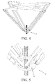
- Figure 4 a second embodiment of the robot according to the invention is shown.
- Figure 5 shows the main parts 21', 22' of the travelling plate 2' with the motion transformation system of the robot in detail.
- This embodiment differs from the first embodiment shown in Figures 1-3 in that the actuators are present at the same level in one plane and in that the second ends of the arms (the joints) are in one plane and at the same level instead of being in two different levels as is the case in the first embodiment.
Landscapes
- Engineering & Computer Science (AREA)
- Robotics (AREA)
- Mechanical Engineering (AREA)
- Manipulator (AREA)
Applications Claiming Priority (1)
| Application Number | Priority Date | Filing Date | Title |
|---|---|---|---|
| NL2008119 | 2012-01-13 |
Publications (1)
| Publication Number | Publication Date |
|---|---|
| EP2614933A1 true EP2614933A1 (de) | 2013-07-17 |
Family
ID=47681657
Family Applications (1)
| Application Number | Title | Priority Date | Filing Date |
|---|---|---|---|
| EP13151225.3A Withdrawn EP2614933A1 (de) | 2012-01-13 | 2013-01-14 | Schneller paralleler Bestückungsautomat mit kompakter Fahrplatte |
Country Status (2)
| Country | Link |
|---|---|
| EP (1) | EP2614933A1 (de) |
| NL (1) | NL2010124C2 (de) |
Cited By (17)
| Publication number | Priority date | Publication date | Assignee | Title |
|---|---|---|---|---|
| CN103600344A (zh) * | 2013-11-12 | 2014-02-26 | 南京理工大学 | 被动铰为球铰的二自由度平面平移并联机构 |
| CN103846909A (zh) * | 2014-02-28 | 2014-06-11 | 天津大学 | 可实现四自由度高速并联机械手 |
| CN105127999A (zh) * | 2015-10-09 | 2015-12-09 | 常州大学 | 一种三平移一转动并联机器人抓放器 |
| CN105127998A (zh) * | 2015-09-08 | 2015-12-09 | 常州大学 | 一种三平移一转动并联机器人平台 |
| CN105127983A (zh) * | 2015-10-09 | 2015-12-09 | 常州大学 | 一种三平移一转动并联机构机械手 |
| CN105856192A (zh) * | 2016-05-10 | 2016-08-17 | 燕山大学 | 存在两条连续转动轴线的四支链二自由度转动并联机构 |
| CN106078688A (zh) * | 2016-07-07 | 2016-11-09 | 燕山大学 | 一种重载自平衡三自由度并联机构 |
| US9513168B2 (en) | 2014-09-23 | 2016-12-06 | Utah State University Research Foundation | Linear-motion stage |
| CN106514624A (zh) * | 2016-12-15 | 2017-03-22 | 常州大学 | 一种可重构四自由度并联机械手 |
| CN106826765A (zh) * | 2017-01-25 | 2017-06-13 | 清华大学 | 包含滑块摇杆机构的四自由度高速并联机器人 |
| RU173465U1 (ru) * | 2016-10-04 | 2017-08-29 | Федеральное государственное бюджетное учреждение науки Институт машиноведения им. А.А. Благонравова Российской академии наук (ИМАШ РАН) | Пространственный механизм с четырьмя степенями свободы |
| CN108656079A (zh) * | 2018-04-13 | 2018-10-16 | 上海大学 | 一种三平一转四自由度的并联机构 |
| CN108858144A (zh) * | 2018-07-11 | 2018-11-23 | 天津大学 | 一种含冗余驱动的六自由度并联机构 |
| CN108972507A (zh) * | 2018-07-30 | 2018-12-11 | 燕山大学 | 一种具有两转动自由度的冗余驱动球面并联机构 |
| CN114083517A (zh) * | 2021-11-25 | 2022-02-25 | 天津大学医疗机器人与智能系统研究院 | 并联机构 |
| CN114770476A (zh) * | 2022-05-16 | 2022-07-22 | 重庆邮电大学 | 一种具有二自由度大转角转动的并联驱动机构 |
| CN120003604A (zh) * | 2025-02-17 | 2025-05-16 | 北京交通大学 | 一种基于Sarrus衍生机构与八面体结合的多模式运动机器人 |
Citations (3)
| Publication number | Priority date | Publication date | Assignee | Title |
|---|---|---|---|---|
| EP1870214A1 (de) * | 2005-02-17 | 2007-12-26 | Fundacion Fatronik | Hochgeschwindigkeitsparallelroboter mit vier freiheitsgraden |
| CN201907121U (zh) * | 2010-12-29 | 2011-07-27 | 天津大学 | 一种具有三维平动一维转动的并联机构 |
| CN101863024B (zh) * | 2010-06-29 | 2011-11-09 | 天津大学 | 一种可实现高速运动的三维平动一维转动并联机构 |
-
2013
- 2013-01-14 EP EP13151225.3A patent/EP2614933A1/de not_active Withdrawn
- 2013-01-14 NL NL2010124A patent/NL2010124C2/en not_active IP Right Cessation
Patent Citations (4)
| Publication number | Priority date | Publication date | Assignee | Title |
|---|---|---|---|---|
| EP1870214A1 (de) * | 2005-02-17 | 2007-12-26 | Fundacion Fatronik | Hochgeschwindigkeitsparallelroboter mit vier freiheitsgraden |
| CN101863024B (zh) * | 2010-06-29 | 2011-11-09 | 天津大学 | 一种可实现高速运动的三维平动一维转动并联机构 |
| CN201907121U (zh) * | 2010-12-29 | 2011-07-27 | 天津大学 | 一种具有三维平动一维转动的并联机构 |
| WO2012088976A1 (zh) * | 2010-12-29 | 2012-07-05 | 天津大学 | 一种具有三维平动一维转动的并联机构 |
Non-Patent Citations (1)
| Title |
|---|
| SEBASTIEN KRUT ET AL: "Heli4: A Parallel Robot for Scara Motions with a Very Compact Traveling Plate and a Symmetrical Design", INTELLIGENT ROBOTS AND SYSTEMS, 2006 IEEE/RSJ INTERNATIONAL CONFERENCE ON, IEEE, PI, 1 October 2006 (2006-10-01), pages 1656 - 1661, XP031006323, ISBN: 978-1-4244-0258-8 * |
Cited By (24)
| Publication number | Priority date | Publication date | Assignee | Title |
|---|---|---|---|---|
| CN103600344A (zh) * | 2013-11-12 | 2014-02-26 | 南京理工大学 | 被动铰为球铰的二自由度平面平移并联机构 |
| CN103846909B (zh) * | 2014-02-28 | 2016-08-24 | 天津大学 | 可实现四自由度高速并联机械手 |
| CN103846909A (zh) * | 2014-02-28 | 2014-06-11 | 天津大学 | 可实现四自由度高速并联机械手 |
| US9879974B2 (en) | 2014-09-23 | 2018-01-30 | Utah State University | Linear-motion stage |
| US9513168B2 (en) | 2014-09-23 | 2016-12-06 | Utah State University Research Foundation | Linear-motion stage |
| CN105127998A (zh) * | 2015-09-08 | 2015-12-09 | 常州大学 | 一种三平移一转动并联机器人平台 |
| CN105127999B (zh) * | 2015-10-09 | 2017-11-10 | 常州大学 | 一种三平移一转动并联机器人抓放器 |
| CN105127999A (zh) * | 2015-10-09 | 2015-12-09 | 常州大学 | 一种三平移一转动并联机器人抓放器 |
| CN105127983A (zh) * | 2015-10-09 | 2015-12-09 | 常州大学 | 一种三平移一转动并联机构机械手 |
| CN105856192A (zh) * | 2016-05-10 | 2016-08-17 | 燕山大学 | 存在两条连续转动轴线的四支链二自由度转动并联机构 |
| CN106078688B (zh) * | 2016-07-07 | 2019-02-22 | 燕山大学 | 一种重载自平衡三自由度并联机构 |
| CN106078688A (zh) * | 2016-07-07 | 2016-11-09 | 燕山大学 | 一种重载自平衡三自由度并联机构 |
| RU173465U1 (ru) * | 2016-10-04 | 2017-08-29 | Федеральное государственное бюджетное учреждение науки Институт машиноведения им. А.А. Благонравова Российской академии наук (ИМАШ РАН) | Пространственный механизм с четырьмя степенями свободы |
| CN106514624B (zh) * | 2016-12-15 | 2018-10-16 | 常州大学 | 一种可重构四自由度并联机械手 |
| CN106514624A (zh) * | 2016-12-15 | 2017-03-22 | 常州大学 | 一种可重构四自由度并联机械手 |
| CN106826765A (zh) * | 2017-01-25 | 2017-06-13 | 清华大学 | 包含滑块摇杆机构的四自由度高速并联机器人 |
| CN106826765B (zh) * | 2017-01-25 | 2019-04-23 | 清华大学 | 包含滑块摇杆机构的四自由度高速并联机器人 |
| CN108656079A (zh) * | 2018-04-13 | 2018-10-16 | 上海大学 | 一种三平一转四自由度的并联机构 |
| CN108858144A (zh) * | 2018-07-11 | 2018-11-23 | 天津大学 | 一种含冗余驱动的六自由度并联机构 |
| CN108858144B (zh) * | 2018-07-11 | 2024-03-15 | 天津大学 | 一种含冗余驱动的六自由度并联机构 |
| CN108972507A (zh) * | 2018-07-30 | 2018-12-11 | 燕山大学 | 一种具有两转动自由度的冗余驱动球面并联机构 |
| CN114083517A (zh) * | 2021-11-25 | 2022-02-25 | 天津大学医疗机器人与智能系统研究院 | 并联机构 |
| CN114770476A (zh) * | 2022-05-16 | 2022-07-22 | 重庆邮电大学 | 一种具有二自由度大转角转动的并联驱动机构 |
| CN120003604A (zh) * | 2025-02-17 | 2025-05-16 | 北京交通大学 | 一种基于Sarrus衍生机构与八面体结合的多模式运动机器人 |
Also Published As
| Publication number | Publication date |
|---|---|
| NL2010124C2 (en) | 2013-10-29 |
| NL2010124A (en) | 2013-07-16 |
Similar Documents
| Publication | Publication Date | Title |
|---|---|---|
| NL2010124C2 (en) | Fast pick-and-place parallel robot with compact travelling plate. | |
| US9308652B2 (en) | Robot module and robot with spacer rods arranged at gravity centers | |
| EP2671689B1 (de) | Roboter mit einem mehrgelenkigen arm sowie steuerverfahren und steuerprogramm dafür | |
| CN110545962B (zh) | 线缆驱动式并联操纵器 | |
| US8812158B2 (en) | Method and handling system for automatically moving a gravity-compensated load body | |
| US10626963B2 (en) | Articulated mechanism for linear compliance | |
| CN109605333B (zh) | 一种弹簧绳索混合驱动支链及三转动自由度并联机器人 | |
| KR101269187B1 (ko) | 와이어로프를 이용하여 추가 자유도를 부여한 병렬 링크 로봇 | |
| Tavakoli et al. | A hybrid pole climbing and manipulating robot with minimum DOFs for construction and service applications | |
| CN110125978B (zh) | 一种基于并联平台驱动的绳牵引机器人 | |
| US20150336266A1 (en) | Pure translational serial manipulator robot having three degrees of freedom with a reduced space requirement | |
| CN106737600B (zh) | 一种含有滚珠丝杠动平台的七自由度搬运机器人 | |
| US20130189063A1 (en) | Industrial Robot Including A Parallel Kinematic Manipulator | |
| US20100031767A1 (en) | Compact Manipulation Robot | |
| DE102010027280A1 (de) | Roboterintegrierter Arbeitsplatz | |
| US10195749B2 (en) | Hinge for use in a tension stiffened and tendon actuated manipulator | |
| CN104096998A (zh) | 一种多自由度并联机构式点焊机器人 | |
| WO2015115887A1 (en) | Robot comprising series-arranged delta assemblies | |
| KR20210009660A (ko) | 드론 탑재용 그리퍼 장치 | |
| CN110815184A (zh) | 一种四自由度高速并联机器人机构 | |
| CN114905543A (zh) | 用于机器人辅助设备的平衡机构 | |
| US11185995B2 (en) | Robot gripper having a drive device | |
| WO2019007448A1 (en) | METHOD FOR HEAVY LOAD HANDLING AND DEVICE FOR HEAVY LOAD HANDLING | |
| JPS62166985A (ja) | マニピユレ−タ | |
| KR102776809B1 (ko) | 틸팅 구조, 매니퓰레이터 및 이를 포함하는 핫셀 |
Legal Events
| Date | Code | Title | Description |
|---|---|---|---|
| PUAI | Public reference made under article 153(3) epc to a published international application that has entered the european phase |
Free format text: ORIGINAL CODE: 0009012 |
|
| AK | Designated contracting states |
Kind code of ref document: A1 Designated state(s): AL AT BE BG CH CY CZ DE DK EE ES FI FR GB GR HR HU IE IS IT LI LT LU LV MC MK MT NL NO PL PT RO RS SE SI SK SM TR |
|
| AX | Request for extension of the european patent |
Extension state: BA ME |
|
| RIN1 | Information on inventor provided before grant (corrected) |
Inventor name: COMPANY, OLIVIER Inventor name: CORNELIS VAN DIJK, ARCHIBALD BASTIAAN Inventor name: PIERROT, FRANCOIS Inventor name: KRUT, SEBASTIEN |
|
| 17P | Request for examination filed |
Effective date: 20140117 |
|
| RBV | Designated contracting states (corrected) |
Designated state(s): AL AT BE BG CH CY CZ DE DK EE ES FI FR GB GR HR HU IE IS IT LI LT LU LV MC MK MT NL NO PL PT RO RS SE SI SK SM TR |
|
| STAA | Information on the status of an ep patent application or granted ep patent |
Free format text: STATUS: THE APPLICATION IS DEEMED TO BE WITHDRAWN |
|
| 18D | Application deemed to be withdrawn |
Effective date: 20200801 |