EP2615046A1 - Système et méthode de manutention de bouteilles - Google Patents
Système et méthode de manutention de bouteilles Download PDFInfo
- Publication number
- EP2615046A1 EP2615046A1 EP13151079.4A EP13151079A EP2615046A1 EP 2615046 A1 EP2615046 A1 EP 2615046A1 EP 13151079 A EP13151079 A EP 13151079A EP 2615046 A1 EP2615046 A1 EP 2615046A1
- Authority
- EP
- European Patent Office
- Prior art keywords
- bottle
- conveyor
- bottles
- segment
- carrying segment
- Prior art date
- Legal status (The legal status is an assumption and is not a legal conclusion. Google has not performed a legal analysis and makes no representation as to the accuracy of the status listed.)
- Granted
Links
Images


Classifications
-
- B—PERFORMING OPERATIONS; TRANSPORTING
- B65—CONVEYING; PACKING; STORING; HANDLING THIN OR FILAMENTARY MATERIAL
- B65G—TRANSPORT OR STORAGE DEVICES, e.g. CONVEYORS FOR LOADING OR TIPPING, SHOP CONVEYOR SYSTEMS OR PNEUMATIC TUBE CONVEYORS
- B65G47/00—Article or material-handling devices associated with conveyors; Methods employing such devices
- B65G47/74—Feeding, transfer, or discharging devices of particular kinds or types
- B65G47/84—Star-shaped wheels or devices having endless travelling belts or chains, the wheels or devices being equipped with article-engaging elements
- B65G47/846—Star-shaped wheels or wheels equipped with article-engaging elements
-
- B—PERFORMING OPERATIONS; TRANSPORTING
- B65—CONVEYING; PACKING; STORING; HANDLING THIN OR FILAMENTARY MATERIAL
- B65G—TRANSPORT OR STORAGE DEVICES, e.g. CONVEYORS FOR LOADING OR TIPPING, SHOP CONVEYOR SYSTEMS OR PNEUMATIC TUBE CONVEYORS
- B65G21/00—Supporting or protective framework or housings for endless load-carriers or traction elements of belt or chain conveyors
- B65G21/10—Supporting or protective framework or housings for endless load-carriers or traction elements of belt or chain conveyors movable, or having interchangeable or relatively movable parts; Devices for moving framework or parts thereof
-
- B—PERFORMING OPERATIONS; TRANSPORTING
- B67—OPENING, CLOSING OR CLEANING BOTTLES, JARS OR SIMILAR CONTAINERS; LIQUID HANDLING
- B67C—CLEANING, FILLING WITH LIQUIDS OR SEMILIQUIDS, OR EMPTYING, OF BOTTLES, JARS, CANS, CASKS, BARRELS, OR SIMILAR CONTAINERS, NOT OTHERWISE PROVIDED FOR; FUNNELS
- B67C7/00—Concurrent cleaning, filling, and closing of bottles; Processes or devices for at least two of these operations
- B67C7/0006—Conveying; Synchronising
- B67C7/004—Conveying; Synchronising the containers travelling along a circular path
- B67C7/0046—Infeed and outfeed devices
-
- B—PERFORMING OPERATIONS; TRANSPORTING
- B65—CONVEYING; PACKING; STORING; HANDLING THIN OR FILAMENTARY MATERIAL
- B65G—TRANSPORT OR STORAGE DEVICES, e.g. CONVEYORS FOR LOADING OR TIPPING, SHOP CONVEYOR SYSTEMS OR PNEUMATIC TUBE CONVEYORS
- B65G2201/00—Indexing codes relating to handling devices, e.g. conveyors, characterised by the type of product or load being conveyed or handled
- B65G2201/02—Articles
- B65G2201/0235—Containers
- B65G2201/0244—Bottles
-
- B—PERFORMING OPERATIONS; TRANSPORTING
- B65—CONVEYING; PACKING; STORING; HANDLING THIN OR FILAMENTARY MATERIAL
- B65G—TRANSPORT OR STORAGE DEVICES, e.g. CONVEYORS FOR LOADING OR TIPPING, SHOP CONVEYOR SYSTEMS OR PNEUMATIC TUBE CONVEYORS
- B65G2201/00—Indexing codes relating to handling devices, e.g. conveyors, characterised by the type of product or load being conveyed or handled
- B65G2201/02—Articles
- B65G2201/0235—Containers
- B65G2201/0244—Bottles
- B65G2201/0247—Suspended bottles
-
- B—PERFORMING OPERATIONS; TRANSPORTING
- B65—CONVEYING; PACKING; STORING; HANDLING THIN OR FILAMENTARY MATERIAL
- B65G—TRANSPORT OR STORAGE DEVICES, e.g. CONVEYORS FOR LOADING OR TIPPING, SHOP CONVEYOR SYSTEMS OR PNEUMATIC TUBE CONVEYORS
- B65G2207/00—Indexing codes relating to constructional details, configuration and additional features of a handling device, e.g. Conveyors
- B65G2207/08—Adjustable and/or adaptable to the article size
-
- B—PERFORMING OPERATIONS; TRANSPORTING
- B67—OPENING, CLOSING OR CLEANING BOTTLES, JARS OR SIMILAR CONTAINERS; LIQUID HANDLING
- B67C—CLEANING, FILLING WITH LIQUIDS OR SEMILIQUIDS, OR EMPTYING, OF BOTTLES, JARS, CANS, CASKS, BARRELS, OR SIMILAR CONTAINERS, NOT OTHERWISE PROVIDED FOR; FUNNELS
- B67C3/00—Bottling liquids or semiliquids; Filling jars or cans with liquids or semiliquids using bottling or like apparatus; Filling casks or barrels with liquids or semiliquids
- B67C3/02—Bottling liquids or semiliquids; Filling jars or cans with liquids or semiliquids using bottling or like apparatus
- B67C3/22—Details
- B67C3/26—Filling-heads; Means for engaging filling-heads with bottle necks
- B67C2003/2668—Means for adapting the filling head to various sizes of containers
Definitions
- the present invention relates to a bottle conveyor for bottling systems and the relative method for operating the same.
- the present invention relates to a bottle conveyor configured to carry glass and/or plastic (PET) and/or similar bottles into, or towards, a machine present in a bottling system, such as, for example, a rinsing machine and/or a sterilising machine and/or a filling machine, to which the following will make explicit reference without thus losing its general nature.
- a machine present in a bottling system such as, for example, a rinsing machine and/or a sterilising machine and/or a filling machine, to which the following will make explicit reference without thus losing its general nature.
- bottling of glass or plastic bottles with liquids for dietary use is typically performed in bottling systems of large dimensions which perform bottling processes generally comprising one or more steps of rinsing the bottles, typically performed by a rinsing machine, or one or more steps of sanitising/sterilising the bottles, typically performed by a sterilising machine, and at least one subsequent step of filling the bottle with liquid, typically performed by a filling machine.
- rinsing, sterilising and filling machines are generally provided with: a platform rotating around a vertical axis, bottle gripping elements, which are mounted around the external edge of the rotating platform at predetermined angular distances from each other, and are configured to clamp the bottle and hold it coupled to the rotating platform and displace it, taking it to a determined position/angle during rotation of the platform; and liquid injector devices comprising nozzles adapted to deliver a predetermined quantity of liquid into the bottles which, depending on the machine type, may be a rinsing liquid or a sanitising liquid or a liquid for dietary use.
- the bottles are generally transferred from one machine to another by means of carrying circuits or conveyor lines provided with conveyors configured so as to: receive an incoming line of bottles and space the bottles from each other so as to deliver the outgoing bottles at a distance congruent with the distance of the bottle gripping elements present on the rotating platform.
- the above conveyors generally comprise a linear conveyor adapted to receive the line of incoming bottles and deliver them appropriately distanced to a rotating bottle transfer conveyor, which is configured so as to clamp the bottles sequentially and carry them along a semicircular transfer path towards a position tangential to the rotating platform, on which the gripping elements clamp the bottles so as to offload them from the rotating transfer conveyor.
- a first type of conveyor wherein the rotating bottle-transfer conveyor generally comprises a rotating bottle-transfer carousel, which is configured so as to clamp the "bottle-body", i.e. the central portion of the bottle present beneath its neck, and to slide the bottles along an underlying sliding plane around the semicircular path, while the linear conveyor generally comprises a bottle conveyor belt, and a bottle distancing mechanism, which is provided with a pair of variable-step screw feeders parallel to and facing each other, which are interposed between the outlet of the conveyor belt and the inlet of the rotating conveyor, and are configured so as to space the bottles according to a predetermined distance corresponding with the loading distance of the bottles onto the rotating transfer carousel.
- the rotating bottle-transfer conveyor generally comprises a rotating bottle-transfer carousel, which is configured so as to clamp the "bottle-body", i.e. the central portion of the bottle present beneath its neck, and to slide the bottles along an underlying sliding plane around the semicircular path
- the linear conveyor generally comprises
- the presence of the distancing mechanism provided with a double screw feeder makes the system inflexible, since whenever the need to change the height of the bottles due to a change in their format arises, very frequent on filling machines of large dimensions, it is necessary to replace the screw feeders of the distancing mechanism with screw feeders suited to the new format/dimensions, and to regulate the heights of the rotating/linear conveyor and/or the carousel and platform.
- a second type of conveyor is also known, wherein the rotating bottle-transfer carousel of the rotating transfer conveyor is configured to clamp the neck of the bottle so as to perform the so-called "neck grip", while the linear conveyor comprises a neck sliding guide configured to support and slide the annular portion carrying the neck of the bottle and a series of air-thrust devices positioned along the sliding guide and adapted to emit air jets towards the bottle in a manner to generate thrust which slides and advances the bottles along the sliding guide and deliver them to the rotating transfer carousel.
- conveyors of the second type described above are particularly flexible to changes in format, and particularly changes in the height of the bottles, they also present the technical problem of not being adapted to be used to transfer pre-sanitised bottles, i.e. containing a predetermined quantity of sanitising liquid, into a rinsing machine and/or a sterilising machine.
- pre-sanitised bottles i.e. containing a predetermined quantity of sanitising liquid
- the air jets emitted by the air-thrust devices are not capable of advancing the bottles along the sliding guide due to their weight.
- the Applicant has therefore conducted a detailed study with the purpose of identifying a solution which specifically achieves the objective of manufacturing a simple and inexpensive conveyor which is easily adapted to a change in the format of the bottles and is also usable to deliver pre-sanitised bottles containing a predetermined quantity of pre-sanitising liquid to a rotating carousel, with grip on the neck, of a machine present in the bottling system.
- the object of the present invention is therefore providing a solution which allows said objective to be achieved.
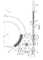
- the number 1 indicates as a whole a bottling conveyor configured to deliver glass and/or plastic (PET) and/or similar bottles 2 into or to a machine 3 present in a bottling system 4.
- PET glass and/or plastic
- the machine 3 may be, for example, a rinsing machine and/or a sterilising machine and/or a filling machine or any other similar machine, while the bottle conveyor 1 may be comprised in the machine 3 itself and/or carry the bottles from one machine 3 to another.
- the machine 3 comprises a rotating platform 5 supported by a casing or a frame resting on the ground (not shown) and designed to rotate around a vertical axis 6, and a plurality of bottle gripping elements 7, which are angularly spaced from each other around the edge of the rotating platform 5, and are configured to clamp/hold the bottle 2 so as to keep it coupled to the rotating platform 5 in a determined position/angle during rotation of the platform.
- the machine 3 also comprises liquid injector devices (not shown), preferably, but not necessarily, comprising nozzles, which are connected by means of the relative conduits (not shown) to a central manifold containing liquid (not shown), and are designed to inject into the bottles 2, on command, a predetermined quantity of liquid which, depending on the machine type, may be a rinsing liquid, a sanitising liquid or a liquid for dietary use.
- liquid injector devices preferably, but not necessarily, comprising nozzles, which are connected by means of the relative conduits (not shown) to a central manifold containing liquid (not shown), and are designed to inject into the bottles 2, on command, a predetermined quantity of liquid which, depending on the machine type, may be a rinsing liquid, a sanitising liquid or a liquid for dietary use.
- the conveyor 1 comprises a rotating conveyor 10 configured to: receive the bottles 2 at an inlet 10a, grip the neck 2a of the bottles 2 to carry them along a semicircular path of transfer towards an outlet 10b arranged in a bottle-transfer position tangential to the rotating platform 5, in which the bottle-grip elements 7 sequentially clamps the bottles 2 to transfer them from the rotating conveyor 10 to the rotating platform 5.
- the bottle conveyor 1 also comprises a linear conveyor 12, which is interposed between a final segment of a bottle carrying line of the bottling system 4 and the rotating conveyor 10, and is configured to: receive the bottles 2 from the final segment of the bottle carrying line and move the bottles 2, supporting the bottom thereof, along a carrying path which ends at the inlet 10a of the rotating conveyor 10.
- the rotating conveyor 10 comprises a bottle-transfer carousel 16, which is designed to rotate around a vertical axis 18, and cooperates with a relative lateral bottle containment guide 19 to move the bottles from the inlet 10a to the outlet 10b along the semicircular transfer path, holding them hanging by gripping the neck 2a.
- the bottle-transfer carousel 16 comprises at least one transfer crown 16a coaxial to the vertical axis 18, a central hub coupled to the outlet shaft of a motor, for example an electric motor (not shown) and a series of spokes connecting the central hub to the transfer crown 16a.
- the transfer crown 16a Around the outer edge of the transfer crown 16a there is a plurality of hollows or grooves 17a angularly spaced at equal distances from each other, which are shaped to house the neck 2a of the bottle 2, while the bottle containment guide 19 comprises a semicircular section bar 19a adapted to hold the bottles 2 trapped in the grooves 17a of the transfer crown 16a.
- the semicircular section bar 19a is arranged coplanar to the lying surface of the transfer crown 16a and extends immediately adjacent to the latter so as to locally surround a segment of the outer edge thereof facing the semicircular transfer path, and is distanced from the outer edge in a manner to keep the necks 2a of the bottles 2 trapped inside the grooves 17a.
- the bottle-transfer carousel 16 also preferably, but not necessarily, comprises a transfer crown 16b arranged beneath the transfer crown 16a coaxial to the vertical axis 18 and rigidly connected to it by means of known connection elements, for example connection pins.
- the bottle containment guide 19 also preferably, but not necessarily, comprises a semicircular section bar (not shown) arranged beneath the semicircular section bar 19a coplanar to the lying surface of the transfer crown 16b and extends immediately adjacent to the latter so as to locally surround a segment of the outer edge thereof facing the semicircular transfer path and is distanced from it in a manner to hold the body of the bottles 2 trapped inside the groove 17b of the transfer crown 16b.
- a semicircular section bar (not shown) arranged beneath the semicircular section bar 19a coplanar to the lying surface of the transfer crown 16b and extends immediately adjacent to the latter so as to locally surround a segment of the outer edge thereof facing the semicircular transfer path and is distanced from it in a manner to hold the body of the bottles 2 trapped inside the groove 17b of the transfer crown 16b.
- the semicircular section bar 19a of the bottle containment guide 19 presents a distal end opposite the distal end facing the rotating platform 5, a straight extension which extends tangentially to the bottle-transfer rotating carousel 16 towards the inlet 10a, and forms a straight guide 20 which delimits together with a straight counter-guide 21 parallel to and distanced from it, an inlet passage or channel 22, which is sized to be crossed by the neck 2a of the bottle 2.
- the guide 20 and the straight counter-guide 21 extend parallel to a longitudinal axis A of reference and are coplanar and distanced from each other in a manner that the neck 2a of the bottles 2 may cross the inlet channel 22 and simultaneously an annular carrying portion of the neck 2a of the bottle 2 may slide freely on the surface of the guide 20 and counter-guide 21.
- connection bridge 23 which extends transversally to the longitudinal axis A, is arranged spanning the inlet channel 22 and presents centrally, above the inlet channel 22, a recess (not shown) shaped to be crossed by the upper portion of the neck 2a of the bottle 2 when the latter slides along the guide 20 and counter-guide 21.
- the straight counter-guide 21 comprises: an elongated sliding plate which extends at inlet 10a, between the straight guide 20 and the bottle-transfer rotating carousel 16 in a constantly coplanar position to the straight guide 20 and to the transfer crown 16a; and a containment frame 25, which defines an extension of the straight counter-guide 21 extending towards the transfer crown 16a in a manner to be locally tangential to it, and has the function of guiding, with the straight guide 20, the neck 2a of the bottle 2 towards the groove 17a of the transfer crown 16a destined to receive said neck 2a during the transfer operation.
- the containment frame 25 is stably attached onto the upper surface of the elongated sliding plate and extends parallel to the longitudinal axis A, remaining on a lying plane arranged above the transfer crown 16a, parallel to it, in a manner not to interfere with its rotation.
- the containment frame 25 also presents a free end tangential to the outer edge of the transfer crown 16a in a manner to be positioned each time, during rotation of the carousel 16, above the groove 17a destined to house the neck 2a of the bottle 2 to be transferred.
- Linear conveyor 12 extends at least partially beneath the inlet 10a of the rotating conveyor 10 or beneath the guide 20 and the counter-guide 21 and is configured in a manner to carry the bottles 2 supporting the corresponding bottoms thereof and deliver them into the inlet channel 22 of the rotating conveyor 10.
- the linear conveyor 12 comprises a motorised conveyor belt, such as a roller belt or any similar belt, configured to support the bottom of the bottle during its advance.
- a motorised conveyor belt such as a roller belt or any similar belt, configured to support the bottom of the bottle during its advance.
- the linear conveyor 12 essentially comprises an initial bottle carrying segment or section 28 arranged on a predetermined reference plane, preferably horizontal, and a final bottle carrying segment or section 29, which is arranged beneath the guide 20 and the straight counter-guide 21, extends parallel to the longitudinal axis A and is configured so as to be moved orthogonally to said predetermined reference plane so as to vary its distance DH from the lying plane of said guide 20 and straight counter-guide 21.
- the linear conveyor 12 also comprises an intermediate bottle carrying segment or section 30 which connects the initial bottle carrying segment 28 to the final bottle carrying segment 29, and is configured to vary its inclination with respect to the predetermined reference plane, on the basis of said orthogonal displacement carried out by said initial bottle carrying segment 28.
- said intermediate bottle carrying segment 30 presents its opposite ends connected to the initial bottle carrying segment 28 and the final bottle carrying segment 29 and is configured in a manner to float or oscillate with respect to them.
- the intermediate bottle carrying segment 30 presents a distal end hinged to an adjacent end of the initial bottle carrying segment 28, in a manner to oscillate about a rotation axis B transversal to longitudinal axis A, and a distal end hinged to an adjacent end of the final bottle carrying segment 29 in a manner to oscillate about a rotation axis C transversal to longitudinal axis A.
- the linear conveyor 12 comprises a raising mechanism 31 designed to displace the final bottle carrying segment 29 orthogonally to the reference plane, and an electronic control unit 32 configured in a manner to control the raising mechanism 31 to ensure it displaces the final segment 29 orthogonally to the predetermined reference plane on the basis of a command, for example a user command or a command generated by a control system, containing information indicating the format and/or height of the bottle to be delivered to the machine.
- a command for example a user command or a command generated by a control system, containing information indicating the format and/or height of the bottle to be delivered to the machine.
- the raising mechanism 31 is of the electromechanical type and comprises jacks interposed between a support surface and a frame/supporting structure of the final segment 29.
- the raising mechanism 31 may comprise actuators or any other known apparatus/device capable of displacing the final segment 29 orthogonally to the reference plane, while the initial bottle carrying segment 28 may preferably, but not necessarily, correspond with the final segment of the bottle carrying line.
- the raising mechanism 31 comprises mechanical means for manual regulation by means of which it is possible manually to regulate orthogonal displacement of the final bottle carrying segment 29 with respect to a reference plane, from and towards the lying plane of the guide 20 and the straight counter-guide 21 so as to regulate the distance DH.
- the rotating conveyor 10 also comprises an upper bracket 33, which extends projecting from the connection bridge 23 and defines an upper containment guide of the bottle 2, with the function of holding the bottles 2 resting on the underlying linear conveyor 12, and in particular on the final segment 29, when said segment reaches the inlet 10a of the rotating conveyor 10.
- the upper bracket 33 is L-shaped, presents its smaller portion fixed centrally to a connection bridge 23 and its larger portion extending parallel to axis A above the inlet channel 22a in an opposite direction to the connection bridge 23, and presents a lower surface facing the underlying linear conveyor 12, on which the upper end of the bottle 2 is adapted to slide 2.
- the operating method of the conveyor 12 envisages the control unit 32 receiving input data indicating the format of the bottle 2, including its height, and controlling the raising mechanism 31 to ensure that it displaces the final carrying segment 29 orthogonally to the reference plane so as to vary the distance DH present between the upper carrying surface of the latter and the lying plane of the guide 20 and the straight counter-guide 21, as a function of the bottle height.
- the intermediate segment 30 is hinged to said segment and to the initial carrying segment 28 to incline progressively.
- the final bottle carrying segment 29 may be displaced between a first operating condition (shown in Figure 3 ), in which the final bottle carrying segment 29 is arranged at a height H1 with respect to the reference plane, on which the initial bottle carrying segment 28 lies, and a second operating condition (shown in Figure 4 ), in which the final carrying segment 29 is arranged at a height H2 ⁇ H1 with respect to the reference plane.
- a first operating condition shown in Figure 3
- a second operating condition shown in Figure 4
- the final carrying segment 29 is arranged at a height H2 ⁇ H1 with respect to the reference plane.
- the conveyor described above presents the advantage of being simple and inexpensive to manufacture, and, thanks to the presence of the linear conveyor configured to regulate the height of its final segment with respect to the reference plane, is easily adapted to a change in the bottle format.
Landscapes
- Engineering & Computer Science (AREA)
- Mechanical Engineering (AREA)
- Filling Of Jars Or Cans And Processes For Cleaning And Sealing Jars (AREA)
- Attitude Control For Articles On Conveyors (AREA)
Priority Applications (1)
| Application Number | Priority Date | Filing Date | Title |
|---|---|---|---|
| PL13151079T PL2615046T3 (pl) | 2012-01-11 | 2013-01-11 | Układ i sposób do manewrowania butelkami |
Applications Claiming Priority (1)
| Application Number | Priority Date | Filing Date | Title |
|---|---|---|---|
| IT000003A ITTV20120003A1 (it) | 2012-01-11 | 2012-01-11 | Unita' convogliatrice di bottiglie per impianti di imbottigliamento e relativo metodo di funzionamento |
Publications (2)
| Publication Number | Publication Date |
|---|---|
| EP2615046A1 true EP2615046A1 (fr) | 2013-07-17 |
| EP2615046B1 EP2615046B1 (fr) | 2014-09-24 |
Family
ID=46001522
Family Applications (1)
| Application Number | Title | Priority Date | Filing Date |
|---|---|---|---|
| EP13151079.4A Not-in-force EP2615046B1 (fr) | 2012-01-11 | 2013-01-11 | Système et méthode de manutention de bouteilles |
Country Status (4)
| Country | Link |
|---|---|
| EP (1) | EP2615046B1 (fr) |
| ES (1) | ES2522874T3 (fr) |
| IT (1) | ITTV20120003A1 (fr) |
| PL (1) | PL2615046T3 (fr) |
Cited By (10)
| Publication number | Priority date | Publication date | Assignee | Title |
|---|---|---|---|---|
| CN103658138A (zh) * | 2013-11-22 | 2014-03-26 | 南京乐惠轻工装备制造有限公司 | 一种载瓶架装置 |
| CN105923594A (zh) * | 2016-06-21 | 2016-09-07 | 浙江国镜药业有限公司 | 直线式全自动塑瓶灌装封盖机及其灌装封盖工艺 |
| WO2017190853A1 (fr) * | 2016-05-03 | 2017-11-09 | Krones Ag | Procédé d'acheminement de contenants et entrée de contenants |
| CN108584853A (zh) * | 2018-04-04 | 2018-09-28 | 日照市生物科技研究院 | 联动式组培瓶清洗灌装烘干生产线 |
| CN109132459A (zh) * | 2018-10-29 | 2019-01-04 | 长沙开元仪器有限公司 | 一种用于煤样瓶的进瓶装置 |
| EP3597572A1 (fr) * | 2018-07-17 | 2020-01-22 | Krones AG | Procédé de répartition de récipients vers une division de machine et machine de traitement pour récipients |
| DE102015106788B4 (de) * | 2015-04-30 | 2020-07-09 | Khs Gmbh | Transportvorrichtung zur Beförderung von stehenden Behältern |
| CN111908401A (zh) * | 2019-05-10 | 2020-11-10 | 克朗斯公司 | 用于将容器导入到容器处理装置的装置和灌装设备 |
| IT201900007845A1 (it) * | 2019-06-03 | 2020-12-03 | Gd Spa | Macchina lavatrice per contenitori, in particolare per prodotti del settore farmaceutico |
| CN114072343A (zh) * | 2019-06-20 | 2022-02-18 | 西德尔包装解决方案公司 | 产品输送设备及加工设施 |
Families Citing this family (2)
| Publication number | Priority date | Publication date | Assignee | Title |
|---|---|---|---|---|
| DE102015121433A1 (de) | 2015-12-09 | 2017-06-14 | Krones Ag | Behälterbehandlungsmaschine und Transporteinrichtung für Behälter |
| DE102017203831A1 (de) | 2017-03-08 | 2018-09-13 | Krones Ag | Behälterbehandlungsmaschine und Transporteinrichtung für Behälter |
Citations (3)
| Publication number | Priority date | Publication date | Assignee | Title |
|---|---|---|---|---|
| DE29505245U1 (de) * | 1995-03-28 | 1996-04-25 | KHS Maschinen- und Anlagenbau AG, 44143 Dortmund | Förderer für Behälterbehandlungsmaschinen |
| DE29722245U1 (de) * | 1997-12-17 | 1998-02-12 | KHS Maschinen- und Anlagenbau AG, 44143 Dortmund | Transportvorrichtung für Kunststoff-Flaschen |
| EP1914181A1 (fr) * | 2006-10-20 | 2008-04-23 | Sidel Participations | Procédé et installation de changement de pas d'entités discrètes convoyées les unes à la suite des autres |
-
2012
- 2012-01-11 IT IT000003A patent/ITTV20120003A1/it unknown
-
2013
- 2013-01-11 EP EP13151079.4A patent/EP2615046B1/fr not_active Not-in-force
- 2013-01-11 PL PL13151079T patent/PL2615046T3/pl unknown
- 2013-01-11 ES ES13151079.4T patent/ES2522874T3/es active Active
Patent Citations (3)
| Publication number | Priority date | Publication date | Assignee | Title |
|---|---|---|---|---|
| DE29505245U1 (de) * | 1995-03-28 | 1996-04-25 | KHS Maschinen- und Anlagenbau AG, 44143 Dortmund | Förderer für Behälterbehandlungsmaschinen |
| DE29722245U1 (de) * | 1997-12-17 | 1998-02-12 | KHS Maschinen- und Anlagenbau AG, 44143 Dortmund | Transportvorrichtung für Kunststoff-Flaschen |
| EP1914181A1 (fr) * | 2006-10-20 | 2008-04-23 | Sidel Participations | Procédé et installation de changement de pas d'entités discrètes convoyées les unes à la suite des autres |
Cited By (16)
| Publication number | Priority date | Publication date | Assignee | Title |
|---|---|---|---|---|
| CN103658138A (zh) * | 2013-11-22 | 2014-03-26 | 南京乐惠轻工装备制造有限公司 | 一种载瓶架装置 |
| DE102015106788B4 (de) * | 2015-04-30 | 2020-07-09 | Khs Gmbh | Transportvorrichtung zur Beförderung von stehenden Behältern |
| WO2017190853A1 (fr) * | 2016-05-03 | 2017-11-09 | Krones Ag | Procédé d'acheminement de contenants et entrée de contenants |
| CN105923594A (zh) * | 2016-06-21 | 2016-09-07 | 浙江国镜药业有限公司 | 直线式全自动塑瓶灌装封盖机及其灌装封盖工艺 |
| CN108584853A (zh) * | 2018-04-04 | 2018-09-28 | 日照市生物科技研究院 | 联动式组培瓶清洗灌装烘干生产线 |
| EP3597572A1 (fr) * | 2018-07-17 | 2020-01-22 | Krones AG | Procédé de répartition de récipients vers une division de machine et machine de traitement pour récipients |
| DE102018211821A1 (de) * | 2018-07-17 | 2020-01-23 | Krones Ag | Verfahren zum Einteilen von Behältern auf eine Maschinenteilung und Behandlungsmaschine für Behälter |
| CN109132459B (zh) * | 2018-10-29 | 2024-04-05 | 长沙开元仪器有限公司 | 一种用于煤样瓶的进瓶装置 |
| CN109132459A (zh) * | 2018-10-29 | 2019-01-04 | 长沙开元仪器有限公司 | 一种用于煤样瓶的进瓶装置 |
| CN111908401A (zh) * | 2019-05-10 | 2020-11-10 | 克朗斯公司 | 用于将容器导入到容器处理装置的装置和灌装设备 |
| US11059679B2 (en) | 2019-05-10 | 2021-07-13 | Krones Ag | Device for supplying containers to a container handling device and filling system |
| CN111908401B (zh) * | 2019-05-10 | 2022-09-09 | 克朗斯公司 | 用于将容器导入到容器处理装置的装置和灌装设备 |
| DE102019112293A1 (de) * | 2019-05-10 | 2020-11-12 | Krones Ag | Vorrichtung zum Zuführen von Behältern zu einer Behälterbehandlungsvorrichtung und Abfüllanlage |
| IT201900007845A1 (it) * | 2019-06-03 | 2020-12-03 | Gd Spa | Macchina lavatrice per contenitori, in particolare per prodotti del settore farmaceutico |
| EP3747561A1 (fr) * | 2019-06-03 | 2020-12-09 | G.D Societa' Per Azioni | Machine à laver pour récipients, en particulier pour des produits de l'industrie pharmaceutique |
| CN114072343A (zh) * | 2019-06-20 | 2022-02-18 | 西德尔包装解决方案公司 | 产品输送设备及加工设施 |
Also Published As
| Publication number | Publication date |
|---|---|
| ES2522874T3 (es) | 2014-11-18 |
| EP2615046B1 (fr) | 2014-09-24 |
| ITTV20120003A1 (it) | 2013-07-12 |
| PL2615046T3 (pl) | 2015-02-27 |
Similar Documents
| Publication | Publication Date | Title |
|---|---|---|
| EP2615046A1 (fr) | Système et méthode de manutention de bouteilles | |
| US11186443B2 (en) | Plant for processing containers | |
| US9090408B2 (en) | Apparatus and method of conveying containers with base guidance | |
| CN208979268U (zh) | 输送星形件 | |
| US7331156B2 (en) | System for securely conveying articles and related components | |
| US8905226B2 (en) | Container handling arrangement with adjustable handling structures for handling different containers and groups of containers, and a method of adjusting adjustable handling structures for handling different containers and groups of containers | |
| US10196253B2 (en) | Container treatment machine and method for supplying and discharging containers to and from the container treatment machine | |
| US9624039B2 (en) | Method and container-processing machine for processing containers | |
| JP5355102B2 (ja) | 容器受渡し装置 | |
| US10106388B2 (en) | Container processing machine and method for delivering containers to and/or removing them from a container processing machine | |
| US9873569B1 (en) | Container treatment machine | |
| CN102633120A (zh) | 带有容器旋转的处理容器的装置和方法 | |
| CN113454005A (zh) | 用于容器的运输设施 | |
| EP3162721A1 (fr) | Appareil de manipulation de récipients | |
| IT201800020914A1 (it) | Gruppo e metodo per il trasferimento e l'orientamento di contenitori | |
| CN106660652A (zh) | 贴标签机 | |
| US9731855B2 (en) | Labeling device for containers | |
| US20200207554A1 (en) | Device for coating containers by means of a coating process and method for operating such a device | |
| JP2013544727A (ja) | 物品ハンドリング機械 | |
| CN209739563U (zh) | 容器处理机 | |
| ITPR940046A1 (it) | Dispositivo per trasferire bottiglie | |
| CN118871381A (zh) | 容器处理设备 | |
| CN210942650U (zh) | 用于容器的处理机 | |
| CN110546090A (zh) | 处理设备以及容器处理机器 | |
| KR102941658B1 (ko) | 화장품 용기 투입 자동화 장치 |
Legal Events
| Date | Code | Title | Description |
|---|---|---|---|
| PUAI | Public reference made under article 153(3) epc to a published international application that has entered the european phase |
Free format text: ORIGINAL CODE: 0009012 |
|
| AK | Designated contracting states |
Kind code of ref document: A1 Designated state(s): AL AT BE BG CH CY CZ DE DK EE ES FI FR GB GR HR HU IE IS IT LI LT LU LV MC MK MT NL NO PL PT RO RS SE SI SK SM TR |
|
| AX | Request for extension of the european patent |
Extension state: BA ME |
|
| RBV | Designated contracting states (corrected) |
Designated state(s): AL AT BE BG CH CY CZ DE DK EE ES FI FR GB GR HR HU IE IS IT LI LT LU LV MC MK MT NL NO PL PT RO RS SE SI SK SM TR |
|
| 17P | Request for examination filed |
Effective date: 20140117 |
|
| GRAP | Despatch of communication of intention to grant a patent |
Free format text: ORIGINAL CODE: EPIDOSNIGR1 |
|
| RIC1 | Information provided on ipc code assigned before grant |
Ipc: B65G 47/84 20060101ALI20140320BHEP Ipc: B67C 7/00 20060101ALI20140320BHEP Ipc: B65G 21/10 20060101AFI20140320BHEP |
|
| INTG | Intention to grant announced |
Effective date: 20140415 |
|
| GRAS | Grant fee paid |
Free format text: ORIGINAL CODE: EPIDOSNIGR3 |
|
| GRAA | (expected) grant |
Free format text: ORIGINAL CODE: 0009210 |
|
| AK | Designated contracting states |
Kind code of ref document: B1 Designated state(s): AL AT BE BG CH CY CZ DE DK EE ES FI FR GB GR HR HU IE IS IT LI LT LU LV MC MK MT NL NO PL PT RO RS SE SI SK SM TR |
|
| REG | Reference to a national code |
Ref country code: GB Ref legal event code: FG4D |
|
| REG | Reference to a national code |
Ref country code: CH Ref legal event code: EP |
|
| REG | Reference to a national code |
Ref country code: AT Ref legal event code: REF Ref document number: 688520 Country of ref document: AT Kind code of ref document: T Effective date: 20141015 |
|
| REG | Reference to a national code |
Ref country code: IE Ref legal event code: FG4D |
|
| REG | Reference to a national code |
Ref country code: DE Ref legal event code: R096 Ref document number: 602013000261 Country of ref document: DE Effective date: 20141106 |
|
| REG | Reference to a national code |
Ref country code: ES Ref legal event code: FG2A Ref document number: 2522874 Country of ref document: ES Kind code of ref document: T3 Effective date: 20141118 |
|
| PG25 | Lapsed in a contracting state [announced via postgrant information from national office to epo] |
Ref country code: LT Free format text: LAPSE BECAUSE OF FAILURE TO SUBMIT A TRANSLATION OF THE DESCRIPTION OR TO PAY THE FEE WITHIN THE PRESCRIBED TIME-LIMIT Effective date: 20140924 Ref country code: FI Free format text: LAPSE BECAUSE OF FAILURE TO SUBMIT A TRANSLATION OF THE DESCRIPTION OR TO PAY THE FEE WITHIN THE PRESCRIBED TIME-LIMIT Effective date: 20140924 Ref country code: NO Free format text: LAPSE BECAUSE OF FAILURE TO SUBMIT A TRANSLATION OF THE DESCRIPTION OR TO PAY THE FEE WITHIN THE PRESCRIBED TIME-LIMIT Effective date: 20141224 Ref country code: SE Free format text: LAPSE BECAUSE OF FAILURE TO SUBMIT A TRANSLATION OF THE DESCRIPTION OR TO PAY THE FEE WITHIN THE PRESCRIBED TIME-LIMIT Effective date: 20140924 Ref country code: GR Free format text: LAPSE BECAUSE OF FAILURE TO SUBMIT A TRANSLATION OF THE DESCRIPTION OR TO PAY THE FEE WITHIN THE PRESCRIBED TIME-LIMIT Effective date: 20141225 |
|
| REG | Reference to a national code |
Ref country code: LT Ref legal event code: MG4D Ref country code: NL Ref legal event code: VDEP Effective date: 20140924 |
|
| PG25 | Lapsed in a contracting state [announced via postgrant information from national office to epo] |
Ref country code: HR Free format text: LAPSE BECAUSE OF FAILURE TO SUBMIT A TRANSLATION OF THE DESCRIPTION OR TO PAY THE FEE WITHIN THE PRESCRIBED TIME-LIMIT Effective date: 20140924 Ref country code: CY Free format text: LAPSE BECAUSE OF FAILURE TO SUBMIT A TRANSLATION OF THE DESCRIPTION OR TO PAY THE FEE WITHIN THE PRESCRIBED TIME-LIMIT Effective date: 20140924 Ref country code: LV Free format text: LAPSE BECAUSE OF FAILURE TO SUBMIT A TRANSLATION OF THE DESCRIPTION OR TO PAY THE FEE WITHIN THE PRESCRIBED TIME-LIMIT Effective date: 20140924 Ref country code: RS Free format text: LAPSE BECAUSE OF FAILURE TO SUBMIT A TRANSLATION OF THE DESCRIPTION OR TO PAY THE FEE WITHIN THE PRESCRIBED TIME-LIMIT Effective date: 20140924 |
|
| REG | Reference to a national code |
Ref country code: PL Ref legal event code: T3 |
|
| REG | Reference to a national code |
Ref country code: AT Ref legal event code: MK05 Ref document number: 688520 Country of ref document: AT Kind code of ref document: T Effective date: 20140924 |
|
| PG25 | Lapsed in a contracting state [announced via postgrant information from national office to epo] |
Ref country code: NL Free format text: LAPSE BECAUSE OF FAILURE TO SUBMIT A TRANSLATION OF THE DESCRIPTION OR TO PAY THE FEE WITHIN THE PRESCRIBED TIME-LIMIT Effective date: 20140924 |
|
| REG | Reference to a national code |
Ref country code: HU Ref legal event code: AG4A Ref document number: E022148 Country of ref document: HU |
|
| PG25 | Lapsed in a contracting state [announced via postgrant information from national office to epo] |
Ref country code: PT Free format text: LAPSE BECAUSE OF FAILURE TO SUBMIT A TRANSLATION OF THE DESCRIPTION OR TO PAY THE FEE WITHIN THE PRESCRIBED TIME-LIMIT Effective date: 20150126 Ref country code: SK Free format text: LAPSE BECAUSE OF FAILURE TO SUBMIT A TRANSLATION OF THE DESCRIPTION OR TO PAY THE FEE WITHIN THE PRESCRIBED TIME-LIMIT Effective date: 20140924 Ref country code: IS Free format text: LAPSE BECAUSE OF FAILURE TO SUBMIT A TRANSLATION OF THE DESCRIPTION OR TO PAY THE FEE WITHIN THE PRESCRIBED TIME-LIMIT Effective date: 20150124 Ref country code: CZ Free format text: LAPSE BECAUSE OF FAILURE TO SUBMIT A TRANSLATION OF THE DESCRIPTION OR TO PAY THE FEE WITHIN THE PRESCRIBED TIME-LIMIT Effective date: 20140924 Ref country code: EE Free format text: LAPSE BECAUSE OF FAILURE TO SUBMIT A TRANSLATION OF THE DESCRIPTION OR TO PAY THE FEE WITHIN THE PRESCRIBED TIME-LIMIT Effective date: 20140924 Ref country code: RO Free format text: LAPSE BECAUSE OF FAILURE TO SUBMIT A TRANSLATION OF THE DESCRIPTION OR TO PAY THE FEE WITHIN THE PRESCRIBED TIME-LIMIT Effective date: 20140924 |
|
| REG | Reference to a national code |
Ref country code: DE Ref legal event code: R082 Ref document number: 602013000261 Country of ref document: DE Representative=s name: PATENTANWAELTE WEICKMANN & WEICKMANN, DE Ref country code: DE Ref legal event code: R082 Ref document number: 602013000261 Country of ref document: DE Representative=s name: WEICKMANN & WEICKMANN PATENTANWAELTE - RECHTSA, DE Ref country code: DE Ref legal event code: R082 Ref document number: 602013000261 Country of ref document: DE Representative=s name: WEICKMANN & WEICKMANN PATENT- UND RECHTSANWAEL, DE |
|
| PG25 | Lapsed in a contracting state [announced via postgrant information from national office to epo] |
Ref country code: AT Free format text: LAPSE BECAUSE OF FAILURE TO SUBMIT A TRANSLATION OF THE DESCRIPTION OR TO PAY THE FEE WITHIN THE PRESCRIBED TIME-LIMIT Effective date: 20140924 |
|
| REG | Reference to a national code |
Ref country code: DE Ref legal event code: R097 Ref document number: 602013000261 Country of ref document: DE |
|
| PG25 | Lapsed in a contracting state [announced via postgrant information from national office to epo] |
Ref country code: DK Free format text: LAPSE BECAUSE OF FAILURE TO SUBMIT A TRANSLATION OF THE DESCRIPTION OR TO PAY THE FEE WITHIN THE PRESCRIBED TIME-LIMIT Effective date: 20140924 |
|
| PLBE | No opposition filed within time limit |
Free format text: ORIGINAL CODE: 0009261 |
|
| STAA | Information on the status of an ep patent application or granted ep patent |
Free format text: STATUS: NO OPPOSITION FILED WITHIN TIME LIMIT |
|
| PG25 | Lapsed in a contracting state [announced via postgrant information from national office to epo] |
Ref country code: LU Free format text: LAPSE BECAUSE OF FAILURE TO SUBMIT A TRANSLATION OF THE DESCRIPTION OR TO PAY THE FEE WITHIN THE PRESCRIBED TIME-LIMIT Effective date: 20150111 |
|
| 26N | No opposition filed |
Effective date: 20150625 |
|
| PG25 | Lapsed in a contracting state [announced via postgrant information from national office to epo] |
Ref country code: MC Free format text: LAPSE BECAUSE OF FAILURE TO SUBMIT A TRANSLATION OF THE DESCRIPTION OR TO PAY THE FEE WITHIN THE PRESCRIBED TIME-LIMIT Effective date: 20140924 |
|
| REG | Reference to a national code |
Ref country code: IE Ref legal event code: MM4A |
|
| REG | Reference to a national code |
Ref country code: FR Ref legal event code: PLFP Year of fee payment: 4 |
|
| PG25 | Lapsed in a contracting state [announced via postgrant information from national office to epo] |
Ref country code: IE Free format text: LAPSE BECAUSE OF NON-PAYMENT OF DUE FEES Effective date: 20150111 |
|
| PG25 | Lapsed in a contracting state [announced via postgrant information from national office to epo] |
Ref country code: SI Free format text: LAPSE BECAUSE OF FAILURE TO SUBMIT A TRANSLATION OF THE DESCRIPTION OR TO PAY THE FEE WITHIN THE PRESCRIBED TIME-LIMIT Effective date: 20140924 |
|
| REG | Reference to a national code |
Ref country code: CH Ref legal event code: PL |
|
| PG25 | Lapsed in a contracting state [announced via postgrant information from national office to epo] |
Ref country code: CH Free format text: LAPSE BECAUSE OF NON-PAYMENT OF DUE FEES Effective date: 20160131 Ref country code: LI Free format text: LAPSE BECAUSE OF NON-PAYMENT OF DUE FEES Effective date: 20160131 |
|
| REG | Reference to a national code |
Ref country code: FR Ref legal event code: PLFP Year of fee payment: 5 |
|
| PG25 | Lapsed in a contracting state [announced via postgrant information from national office to epo] |
Ref country code: MT Free format text: LAPSE BECAUSE OF FAILURE TO SUBMIT A TRANSLATION OF THE DESCRIPTION OR TO PAY THE FEE WITHIN THE PRESCRIBED TIME-LIMIT Effective date: 20140924 |
|
| PG25 | Lapsed in a contracting state [announced via postgrant information from national office to epo] |
Ref country code: BG Free format text: LAPSE BECAUSE OF FAILURE TO SUBMIT A TRANSLATION OF THE DESCRIPTION OR TO PAY THE FEE WITHIN THE PRESCRIBED TIME-LIMIT Effective date: 20140924 |
|
| PG25 | Lapsed in a contracting state [announced via postgrant information from national office to epo] |
Ref country code: TR Free format text: LAPSE BECAUSE OF FAILURE TO SUBMIT A TRANSLATION OF THE DESCRIPTION OR TO PAY THE FEE WITHIN THE PRESCRIBED TIME-LIMIT Effective date: 20140924 |
|
| PG25 | Lapsed in a contracting state [announced via postgrant information from national office to epo] |
Ref country code: BE Free format text: LAPSE BECAUSE OF FAILURE TO SUBMIT A TRANSLATION OF THE DESCRIPTION OR TO PAY THE FEE WITHIN THE PRESCRIBED TIME-LIMIT Effective date: 20140924 |
|
| REG | Reference to a national code |
Ref country code: FR Ref legal event code: PLFP Year of fee payment: 6 |
|
| PG25 | Lapsed in a contracting state [announced via postgrant information from national office to epo] |
Ref country code: SM Free format text: LAPSE BECAUSE OF FAILURE TO SUBMIT A TRANSLATION OF THE DESCRIPTION OR TO PAY THE FEE WITHIN THE PRESCRIBED TIME-LIMIT Effective date: 20140924 |
|
| PG25 | Lapsed in a contracting state [announced via postgrant information from national office to epo] |
Ref country code: MK Free format text: LAPSE BECAUSE OF FAILURE TO SUBMIT A TRANSLATION OF THE DESCRIPTION OR TO PAY THE FEE WITHIN THE PRESCRIBED TIME-LIMIT Effective date: 20140924 |
|
| PG25 | Lapsed in a contracting state [announced via postgrant information from national office to epo] |
Ref country code: AL Free format text: LAPSE BECAUSE OF FAILURE TO SUBMIT A TRANSLATION OF THE DESCRIPTION OR TO PAY THE FEE WITHIN THE PRESCRIBED TIME-LIMIT Effective date: 20140924 |
|
| PGFP | Annual fee paid to national office [announced via postgrant information from national office to epo] |
Ref country code: ES Payment date: 20190225 Year of fee payment: 7 Ref country code: FR Payment date: 20190128 Year of fee payment: 7 Ref country code: IT Payment date: 20190107 Year of fee payment: 7 Ref country code: PL Payment date: 20190103 Year of fee payment: 7 Ref country code: GB Payment date: 20190130 Year of fee payment: 7 |
|
| PGFP | Annual fee paid to national office [announced via postgrant information from national office to epo] |
Ref country code: HU Payment date: 20190108 Year of fee payment: 7 |
|
| PGFP | Annual fee paid to national office [announced via postgrant information from national office to epo] |
Ref country code: DE Payment date: 20190401 Year of fee payment: 7 |
|
| REG | Reference to a national code |
Ref country code: DE Ref legal event code: R119 Ref document number: 602013000261 Country of ref document: DE |
|
| GBPC | Gb: european patent ceased through non-payment of renewal fee |
Effective date: 20200111 |
|
| PG25 | Lapsed in a contracting state [announced via postgrant information from national office to epo] |
Ref country code: DE Free format text: LAPSE BECAUSE OF NON-PAYMENT OF DUE FEES Effective date: 20200801 Ref country code: FR Free format text: LAPSE BECAUSE OF NON-PAYMENT OF DUE FEES Effective date: 20200131 Ref country code: GB Free format text: LAPSE BECAUSE OF NON-PAYMENT OF DUE FEES Effective date: 20200111 |
|
| PG25 | Lapsed in a contracting state [announced via postgrant information from national office to epo] |
Ref country code: HU Free format text: LAPSE BECAUSE OF NON-PAYMENT OF DUE FEES Effective date: 20200112 |
|
| PG25 | Lapsed in a contracting state [announced via postgrant information from national office to epo] |
Ref country code: IT Free format text: LAPSE BECAUSE OF NON-PAYMENT OF DUE FEES Effective date: 20200111 |
|
| REG | Reference to a national code |
Ref country code: ES Ref legal event code: FD2A Effective date: 20210602 |
|
| PG25 | Lapsed in a contracting state [announced via postgrant information from national office to epo] |
Ref country code: ES Free format text: LAPSE BECAUSE OF NON-PAYMENT OF DUE FEES Effective date: 20200112 |
|
| PG25 | Lapsed in a contracting state [announced via postgrant information from national office to epo] |
Ref country code: PL Free format text: LAPSE BECAUSE OF NON-PAYMENT OF DUE FEES Effective date: 20200111 |