EP2615217B1 - Vorrichtung zum Regulieren des Spülwasserabflusses eines Spülkastens - Google Patents
Vorrichtung zum Regulieren des Spülwasserabflusses eines Spülkastens Download PDFInfo
- Publication number
- EP2615217B1 EP2615217B1 EP13000111.8A EP13000111A EP2615217B1 EP 2615217 B1 EP2615217 B1 EP 2615217B1 EP 13000111 A EP13000111 A EP 13000111A EP 2615217 B1 EP2615217 B1 EP 2615217B1
- Authority
- EP
- European Patent Office
- Prior art keywords
- movable shutter
- tank
- port
- discharge
- siphon
- Prior art date
- Legal status (The legal status is an assumption and is not a legal conclusion. Google has not performed a legal analysis and makes no representation as to the accuracy of the status listed.)
- Not-in-force
Links
Images


Classifications
-
- E—FIXED CONSTRUCTIONS
- E03—WATER SUPPLY; SEWERAGE
- E03D—WATER-CLOSETS OR URINALS WITH FLUSHING DEVICES; FLUSHING VALVES THEREFOR
- E03D1/00—Water flushing devices with cisterns ; Setting up a range of flushing devices or water-closets; Combinations of several flushing devices
- E03D1/02—High-level flushing systems
- E03D1/06—Cisterns with tube siphons
- E03D1/08—Siphon action initiated by air or water pressure
- E03D1/082—Siphon action initiated by air or water pressure in tube siphons
- E03D1/085—Siphon action initiated by air or water pressure in tube siphons by injection of air or water in the short leg of the siphon
-
- E—FIXED CONSTRUCTIONS
- E03—WATER SUPPLY; SEWERAGE
- E03D—WATER-CLOSETS OR URINALS WITH FLUSHING DEVICES; FLUSHING VALVES THEREFOR
- E03D1/00—Water flushing devices with cisterns ; Setting up a range of flushing devices or water-closets; Combinations of several flushing devices
- E03D1/02—High-level flushing systems
- E03D1/14—Cisterns discharging variable quantities of water also cisterns with bell siphons in combination with flushing valves
- E03D1/141—Cisterns discharging variable quantities of water also cisterns with bell siphons in combination with flushing valves in cisterns with tube siphons and with tube siphons in combination with flushing valves
-
- E—FIXED CONSTRUCTIONS
- E03—WATER SUPPLY; SEWERAGE
- E03D—WATER-CLOSETS OR URINALS WITH FLUSHING DEVICES; FLUSHING VALVES THEREFOR
- E03D1/00—Water flushing devices with cisterns ; Setting up a range of flushing devices or water-closets; Combinations of several flushing devices
- E03D1/02—High-level flushing systems
- E03D1/14—Cisterns discharging variable quantities of water also cisterns with bell siphons in combination with flushing valves
- E03D1/142—Cisterns discharging variable quantities of water also cisterns with bell siphons in combination with flushing valves in cisterns with flushing valves
-
- E—FIXED CONSTRUCTIONS
- E03—WATER SUPPLY; SEWERAGE
- E03D—WATER-CLOSETS OR URINALS WITH FLUSHING DEVICES; FLUSHING VALVES THEREFOR
- E03D5/00—Special constructions of flushing devices, e.g. closed flushing system
- E03D5/02—Special constructions of flushing devices, e.g. closed flushing system operated mechanically or hydraulically (or pneumatically) also details such as push buttons, levers and pull-card therefor
- E03D5/024—Operated hydraulically or pneumatically
-
- E—FIXED CONSTRUCTIONS
- E03—WATER SUPPLY; SEWERAGE
- E03D—WATER-CLOSETS OR URINALS WITH FLUSHING DEVICES; FLUSHING VALVES THEREFOR
- E03D1/00—Water flushing devices with cisterns ; Setting up a range of flushing devices or water-closets; Combinations of several flushing devices
- E03D1/02—High-level flushing systems
- E03D1/14—Cisterns discharging variable quantities of water also cisterns with bell siphons in combination with flushing valves
- E03D2001/147—Cisterns discharging variable quantities of water also cisterns with bell siphons in combination with flushing valves having provisions for active interruption of flushing
Definitions
- the present invention relates to the control of the discharge of water from the tank of a flushing system, for example a flushing system for sanitary fixtures and, in particular, a device which allows to stop the discharge of water, once initiated, even before the complete emptying of the flushing system tank.
- Flushing systems are currently already known and widespread on the market, providing the possibility to adjust the amount of water that is needed to be used for the expulsion of the waste from the sanitary fixtures.
- flushing systems of a known type envisage two activation buttons: a first button is intended to the complete emptying of the tank without the possibility of an intermediate stop, while a second button, generally alongside the first, activates the discharge after it has been pressed but stops it at the time of its release.
- a flushing system for the discharge of water in a sanitary fixture of this type is described for example in French patent application n. FR-A-1194321 , wherein the flushing system comprises a tank, means for feeding a predetermined volume of water in the tank and a siphon housed inside the tank.
- the siphon has a priming port obstructed by a movable shutter, a free extraction port, an upper bend arranged between said two ports and a discharge port.
- the movable shutter is controlled by a rod between a priming port open position, in which the priming port is open to start the discharge of water from the tank, and a priming port closed position.
- the depression condition that establishes in the siphon starts the water flow, by suction, also from the free extraction port; once the priming port is opened, also if the movable shutter returns to the closed position thereof, the water flow from the free extraction port continues until the complete emptying of the tank.
- GB-A-2346159 discloses a device for enabling the duration flush to be set by controlling the moment at which air is introduced into the siphon in order to stop the flushing. This document discloses a solution to a similar technical problem of the present invention, but proposes a solution quite different. Indeed, the volume of the flush can only be mechanically adjusted to a preset amount and does not depend from the start/stop condition of the actuating means.
- FR-A-1518439 and US-A-2615173 disclose systems for actuating the flush similar to those of the present invention, namely systems which provide a button acting on a pneumatic circuit. Further examples of old generation flushing systems provided with a siphon can also be found in U.S. patents no. US-A-5301375 and n. US-A-2957182 .
- the object of the present invention is to propose a device which allows to control the discharge of water from the tank of a flushing system provided with a siphon and, in particular, to stop the discharge of water before the complete emptying of the tank.
- Another object of the present invention is to propose a device of the type mentioned above which is structurally simple and easy to assemble even on flushing systems already installed.
- a further object of the present invention is to propose a flushing system which provides, already in the production step, the possibility of controlling the discharge of water from the tank.
- a device for controlling the discharge of water from the tank of a flushing system comprising a siphon housed in the tank and wherein the siphon has a priming port obstructed by a movable shutter, a free extraction port, at least one upper bend arranged between said two ports and a discharge port; the movable shutter is controlled by a rod between an opening position of the priming port, in which the priming port is open to start the discharge of water from the tank, and a closed position of the priming port.
- the device according to the invention advantageously comprises an auxiliary valve actuable by the movable shutter between an open position, in which air is introduced at atmospheric pressure into the upper bend of the siphon, and a closed position in which the establishment of a depression condition is allowed in the upper bend of the siphon, at the time of discharge.
- the device simply comprises a pipe mountable on the upper bend of the siphon to put in fluid communication the inner space of the siphon with the atmosphere.
- the auxiliary valve intended to control the fluid communication between the siphon and the atmosphere comprises a stem axially sliding within the pipe.
- One or more elements for guiding the sliding stem can be advantageously arranged in the pipe.
- the pipe preferably comprises one or more through holes along its lateral wall to allow communication between the inside of the siphon and the outside atmosphere.
- the device preferably comprises at least one element of rigid connection between the rod of the movable shutter and the stem of the auxiliary valve to move in an integral manner the auxiliary valve and the movable shutter.
- the rigid connecting element can be made of any material, whether plastic or metal, provided that it retains the characteristics of rigidity of the connection. The choice of the material may however depend on various factors, for example the resistance to rust and corrosion, its weight or other considerations related to cost, ease of processing or the like.
- the invention further relates to a flushing system for the discharge of water, comprising a tank, means for feeding a predetermined volume of water in the tank and a siphon housed in the tank; the siphon has a priming port obstructed by a movable shutter, a free extraction port, at least one upper rod arranged between said two ports and a discharge port.
- the movable shutter is controlled by a rod between an open position of the priming port, in which the priming port is open to start the discharge of water from the tank, and a closed position of the priming port; and means to actuate the movement of the movable shutter between the two opening and closing positions of the priming port.
- the flushing system is advantageously provided with a device for controlling the discharge of water from the tank which comprises an auxiliary valve actuated by the movable shutter between an open position, in which air is introduced at atmospheric pressure in the upper bend of the siphon, and a closed position in which the establishment of a depression condition is allowed in the upper bend of the siphon at the time of discharge.
- the means for actuating the movement of the movable shutter comprise a pneumatic circuit comprising a pump actuatable by a button and a cylinder in which a piston slides bound to the movable shutter rod.
- a process for controlling the discharge of a flushing system comprising a tank, means for feeding a predetermined volume of water in the tank and a siphon housed in the tank; the siphon has a priming port obstructed by a movable shutter, a free extraction port, at least one upper bend arranged between these two ports and a discharge port.
- the movable shutter is controlled by a rod between an open position of the priming port, in which the priming port is open to start the discharge of water from the tank, and a closed position of the priming port; and means to actuate the movement of the movable shutter between the two positions.
- the process comprises the steps of:
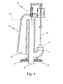
- FIG. 1 Shown in Figure 1 is a flushing system comprising a tank 10 in which water is supplied through a valve 20 being controlled in a known manner by a float 25.
- the valve 20 is adjusted so as to stop the incoming water flow from the water supply when the water reaches a maximum level LT to maintain a predetermined volume of water in the tank 10.
- a siphon 30 which comprises a priming port 31 obstructed by a movable shutter 32, e.g. a half sphere shutter controlled by a rod 33.
- the siphon 30 also comprises a free extraction port 34, arranged at the opposite end of the channel defined by the siphon with respect to the priming port 31, and a discharge port 35.
- the siphon 30 is shaped so as to define at least one upper bend 36 between the priming port 31 and the free extraction port 34.
- the means for actuating the movement of the movable shutter 32 include for example a pneumatic circuit 40 comprising a pump 41 actuatable by a button 42 and a cylinder 43 in which a piston 44 slides bound to the rod 33 of the movable shutter 32.
- the flushing system advantageously comprises a device 50 for controlling the discharge of water from the tank 10 so as to be able to stop the water flow from the free extraction port 34 at the moment when the pressure is released on the button 42 of the pump 41 to actuate the movement of the movable shutter 32.
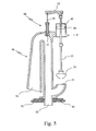
- the device 50 shown in more detail in Figure 2 , comprises an auxiliary valve 51 actuated by the rod 33 of the movable shutter 32; the auxiliary valve 51 includes a stem 52 that is axially slidable within a pipe 60 represented in greater detail in Figure 3 .
- a rigid linking member 55 connects the rod 33 of the movable shutter 32 with the stem 52 of the auxiliary valve 51 to move the auxiliary valve 51 and the movable shutter 32 in an integral manner.
- the pipe 60 is mounted on the upper bend 36 of the siphon 30 and allows to put in fluid communication the inner space of the siphon 30 with the atmosphere. Through holes 61 along its side wall are in fact provided so that, when the valve 51 is in the position of Figure 2 , the atmospheric pressure can be ensured inside the siphon 30 and, more particularly, in the vicinity of the upper bend 36 of the siphon.
- the pipe 60 comprises a threaded bottom end 62 which is screwed into a threaded hole 37 obtained in the siphon 30 and a threaded upper end 63 which receives a threaded plug 64, the latter preferably also provided with a guide element 65 for facilitating the sliding movement of the stem 52.
- the rigid linking member 55 drags the stem 52 of the auxiliary valve 51 therewith by bringing this latter in closing position.
- the siphon 30 is in a depression condition, generated by the water flow passing through the priming port 31, and is therefore permitted the intake of water also through the free extraction port 34.
- Both water flows from the ports 31 and 34 thus reach the discharge port 35; in known flushing systems of this type, i.e. free from a control device 50, the water flow from the free extraction port 34 continues even if the pressure is released on the button 42, and therefore also when the movable shutter 32 returns to the closed condition of the priming port 31.
- the water withdrawal from the tank 10 then only stops at the complete emptying of the tank 10, i.e. when the lower level of the water in the tank 10 reaches the level LB ( Figure 1 ) in which air at atmospheric pressure can enter again into the siphon 30 through the free extraction port 34.
- the piston 44 descends again towards the lower position, such as that represented in Figures 1 and 4 , consequently dragging the movable shutter 32 in the closing condition of the priming port 31.
- the auxiliary valve 51 whose stem 52 is rigidly connected to the rod 33, turns back in the open condition and restores the atmospheric pressure inside the siphon 30. Therefore, by re-establishing in the siphon the pressure condition equal to that of the external environment, the water flow through the free extraction port 34 is automatically stopped.
- actuating means may also be made in the form of mechanical means, by way of suitable lever systems and/or joints, instead of the means represented here in the form of a pneumatic circuit 40.
Landscapes
- Engineering & Computer Science (AREA)
- Health & Medical Sciences (AREA)
- Life Sciences & Earth Sciences (AREA)
- Hydrology & Water Resources (AREA)
- Public Health (AREA)
- Water Supply & Treatment (AREA)
- Mechanical Engineering (AREA)
- Aviation & Aerospace Engineering (AREA)
- Jet Pumps And Other Pumps (AREA)
- Stringed Musical Instruments (AREA)
- Soil Working Implements (AREA)
- Output Control And Ontrol Of Special Type Engine (AREA)
Claims (9)
- Vorrichtung zum Steuern der Abgabe von Wasser aus dem Behälter (10) eines Spülsystems, wobei das Spülsystem einen Siphon (30) umfasst, der in dem Behälter (10) untergebracht ist und wobei der Siphon (30) eine Ansaugöffnung (31) aufweist, welche durch einen beweglichen Verschluss (32) abgeriegelt ist, eine freie Entnahmeöffnung (34), mindestens eine obere Krümmung (36), welche zwischen den zwei genannten Öffnungen (31, 34) angeordnet ist, und eine Abgabeöffnung (35) umfasst, wobei der beweglichen Verschluss (32) durch eine Stange (33) zwischen einer offenen Position der Ansaugöffnung (31), in welchem die Ansaugöffnung (31) geöffnet ist, um die Abgabe on Wasser aus dem Behälter (10) zu starten, und einer geschlossenen Position der Ansaugöffnung (31) gesteuert ist, wobei die Vorrichtung dadurch gekennzeichnet ist, dass sie ein Hilfsventil (51) umfasst, welches mit der Stange (33) des beweglichen Verschlusses (32) zwischen einer offenen Position, in welcher Luft bei Atmosphärendruck in die obere Krümmung (36) des genannten Siphons (30) eingeführt wird, und einer geschlossenen Position, in welcher das Erreichen eines Depressionszustandes in der oberen Krümmung (36) des Siphons (30) zum Zeitpunkt der Abgabe ermöglicht ist, betätigt werden kann.
- Vorrichtung gemäß Anspruch 1, umfassend ein Rohr (60), welches auf der oberen Krümmung (36) des Siphons (30) montierbar ist, um den Innenraum des Siphons (30) in Fluidverbindung mit der Atmosphäre zu setzen.
- Vorrichtung gemäß Anspruch 2, wobei das Hilfsventil (51) einen Schaft (52) umfasst, der axial innerhalb des Rohres (60) verschiebbar ist.
- Vorrichtung gemäß einem der vorherigen Ansprüche, wobei das Rohr (60) ein oder mehrere Durchgangslöcher (61) entlang seiner Seitenwand umfasst.
- Vorrichtung gemäß einem der vorherigen Ansprüche, umfassend mindestens ein Element (55) der starren Verbindung zwischen der Stange (33) des beweglichen Verschlusses (32) und dem Schaft (52) des Hiffsventils (51), um das Hilfsventil (51) und den beweglichen Verschluss (32) in einer integralen Weise zu bewegen.
- Spülsystem zur Abgabe von Wasser, umfassend einen Behälter (10), Mittel (20, 25) zum Zuführen eines vordefinierten Volumens von Wasser in den Behälter (10), einen Siphon (30), der in dem Behälter (10) untergebracht ist und eine Ansaugöffnung (31) aufweist, welche durch einen beweglichen Verschluss (32) abgeriegelt ist, eine freie Entnahmeöffnung (34), mindestens eine obere Krümmung (36), welche zwischen den zwei genannten Öffnungen (31, 34) angeordnet ist, und eine Abgabeöffnung (35), wobei der bewegliche Verschluss (32) durch eine Stange (33) zwischen einer offenen Position der Ansaugöffnung (31), in welchem die Ansaugöffnung (31) geöffnet ist, um die Abgabe on Wasser aus dem Behälter (10) zu starten, und einer geschlossenen Position der Ansaugöffnung (31) gesteuert ist; und Mittel (40-44) zur Betätigung der Bewegung des beweglichen Verschlusses (32) wischen den zwei Positionen, gekennzeichnet dadurch, dass dieses eine Vorrichtung zur Steuerung der Abgabe von Wasser aus dem Behälter (10) gemäß einem der Ansprüche 1 bis 5 umfasst.
- Spülsystem gemäß Anspruch 6, wobei die Mittel (40-44) zur Betätigung der Bewegung des beweglichen Verschlusses (32) einen Druckluftkreis (40) umfassen, welcher eine Pumpe (41) umfasst, die durch einen Druckknopf (42) betätigbar ist, und einen Zylinder (43) umfasst, in welchem ein an die Stange (33) des beweglichen Verschlusses (32) gebundener Kolben (44) gleitet.
- Verfahren zur Steuerung der Abgabe von Wasser aus einem Spütsystem, wobei das Spülsystem einen Behälter (10), Mittel (20, 25) zum Zuführen eines vordefinierten Volumens von Wasser in den Behälter (10), einen Siphon (30), der in dem Behälter (10) untergebracht ist und eine Ansaugöffnung (31) aufweist, welche durch einen beweglichen Verschluss (32) verriegelt ist, eine freie Entnahmeöffnung (34), mindestens eine obere Krümmung (36), welche zwischen den zwei genannten Öffnungen (31, 34) angeordnet ist, und eine Abgabeöffnung (35) umfasst, wobei der bewegliche Verschluss (32) durch eine Stange (33) zwischen einer offenen Position der Ansaugöffnung (31), in welchem die Ansaugöffnung (31) geöffnet ist, um die Abgabe on Wasser aus dem Behälter (10) zu starten, und einer geschlossenen Position der Ansaugöffnung (31) gesteuert ist; und Mittel (40-44) zur Betätigung der Bewegung des beweglichen Verschlusses (32) zwischen den zwei Positionen umfasst, wobei das Verfahren die folgenden Schritte umfasst:a) Füllen des Spülsystem-Behälters (10) mit Wasser bis zu einem vordefinierten Maximalpegel (LT);b) Aktivieren der Mittel (40-44) zum Steuern der Bewegung des beweglichen Verschlusses (32) in der offenen Position der Ansaugöffnung (31), so dass der Wasserfluss von der Ansaugöffnung (31) und von der freien Entnahmeöffnung (34) in Richtung der Abgabeöffnung (35) aktiviert wird;c) Unterbrechen der Aktivierung der Mittel (40-44) zur Betätigung des Bewegung des beweglichen Verschlusses (32) in der geschlossenen Position der Ansaugöffnung (31), gekennzeichnet durch den Schritt:d) Anhalten des Wesserflusses von der freien Entnahmeöffnung (34) durch Einleiten von Luft bei Atmospharendruck in der oberen Krümmung (36) des Siphons (30) zu einem Zeitpunkt, an dem die Aktivierung der Mittel (40-44) zur Betätigung der Bewegung des beweglichen Verschlusses (32) unterbrochen ist.
- Verfahren gemäß Anspruch 8, wobei der Schritt d) durch starre Begrenzung der Bewegung der Steuerstange (33) des beweglichen Verschlusses (32) zu dem Schaft (52) eines Hilfsventils (51) ausgeführt wird, wobei dieses so durch die Stange (33) des beweglichen Verschlusses (32) zwischen einer offenen Position, in welcher Luft bei Atmosphärendruck in die obere Krümmung (36) des genannten Siphons (30) eingeführt wird, und einer geschlossenen Position, in welcher das Erreichen eines Depressionszustandes in der oberen Krümmung (36) des Siphons (30) zum Zeitpunkt der Abgabe ermöglicht ist, betätigt wird.
Applications Claiming Priority (1)
| Application Number | Priority Date | Filing Date | Title |
|---|---|---|---|
| IT000002A ITLE20120002A1 (it) | 2012-01-12 | 2012-01-12 | Regolatore del tempo di scarico per sciacquone di vecchia generazione |
Publications (2)
| Publication Number | Publication Date |
|---|---|
| EP2615217A1 EP2615217A1 (de) | 2013-07-17 |
| EP2615217B1 true EP2615217B1 (de) | 2014-12-17 |
Family
ID=45998426
Family Applications (1)
| Application Number | Title | Priority Date | Filing Date |
|---|---|---|---|
| EP13000111.8A Not-in-force EP2615217B1 (de) | 2012-01-12 | 2013-01-10 | Vorrichtung zum Regulieren des Spülwasserabflusses eines Spülkastens |
Country Status (2)
| Country | Link |
|---|---|
| EP (1) | EP2615217B1 (de) |
| IT (1) | ITLE20120002A1 (de) |
Families Citing this family (3)
| Publication number | Priority date | Publication date | Assignee | Title |
|---|---|---|---|---|
| GB201316243D0 (en) * | 2013-09-12 | 2013-10-30 | Dudley Thomas Ltd | Syphon assembly and actuator therefor |
| GB201416802D0 (en) * | 2014-09-12 | 2014-11-05 | Dudley Thomas Ltd | Syphon assembly and actuator therefor |
| IT201600116262A1 (it) * | 2016-11-17 | 2017-02-17 | Giovanni Bonanno | Vaschetta raccogli condensa autosvuotante per cassetta wc |
Family Cites Families (7)
| Publication number | Priority date | Publication date | Assignee | Title |
|---|---|---|---|---|
| FR1194321A (de) * | 1959-11-09 | |||
| GB478898A (en) * | 1935-09-06 | 1938-01-27 | Ruggero Niccolai | Improvements in hydraulic control devices for liquid discharge siphons |
| US2615173A (en) * | 1948-12-06 | 1952-10-28 | Lockair Pty Ltd | Flushing cistern |
| US2957182A (en) * | 1956-01-12 | 1960-10-25 | Dispositivos Ind S A | Siphon with manometric discharge control |
| FR1518439A (fr) * | 1967-04-11 | 1968-03-22 | Perfectionnements aux chasses d'eau pour water-closets et autres applications | |
| US5301375A (en) * | 1993-03-09 | 1994-04-12 | Osmond John S | Primer tank-checkvalve syphon toilet flushing apparatus |
| GB2346159A (en) * | 1998-10-22 | 2000-08-02 | John Henry May | Regulating amount of discharge from siphon-discharge flushing cistern |
-
2012
- 2012-01-12 IT IT000002A patent/ITLE20120002A1/it unknown
-
2013
- 2013-01-10 EP EP13000111.8A patent/EP2615217B1/de not_active Not-in-force
Also Published As
| Publication number | Publication date |
|---|---|
| ITLE20120002A1 (it) | 2013-07-13 |
| EP2615217A1 (de) | 2013-07-17 |
Similar Documents
| Publication | Publication Date | Title |
|---|---|---|
| US9464420B2 (en) | Leak detection on flush valve | |
| WO2014207365A8 (fr) | Dispositif de commande de remplissage de chasse d'eau | |
| US9611632B2 (en) | Toilet controls | |
| AU2014250737A1 (en) | Drainage fitting for a cistern | |
| TWI683946B (zh) | 沖水閥配件和倂入該配件的馬桶沖水系統 | |
| EP2615217B1 (de) | Vorrichtung zum Regulieren des Spülwasserabflusses eines Spülkastens | |
| US10100502B2 (en) | Syphon assembly and actuator therefor | |
| US9359752B2 (en) | Toilet discharge valve assembly having moveable buoyant float therein | |
| US8430118B2 (en) | Automatic flush device | |
| CN215948375U (zh) | 冲洗阀总成及包括其的马桶 | |
| US20100224805A1 (en) | Hydraulic actuating device | |
| EP2205802B1 (de) | Spülventil | |
| CN101454516A (zh) | 阀装置 | |
| KR101208146B1 (ko) | 급수량 조절이 가능한 자동급수장치 | |
| EP3039323B1 (de) | Flüssigkeitsausstossventil | |
| WO2007050299A3 (en) | Automatic flush actuation apparatus | |
| AU670644B2 (en) | Device with control of the speed of return for regulating and controlling the flow of water from flushing cisterns in sanitary installations | |
| EP3452666B1 (de) | Betätigung für spülventil | |
| US20180002907A1 (en) | An inlet valve arrangement for a toilet cistern | |
| FI4095324T3 (fi) | Huuhtelujärjestelmä | |
| WO1993016240A1 (en) | Mains pressure flusher valve | |
| WO2009155619A3 (en) | Cistern float valve equipment | |
| GB2379942A (en) | Water saving device for a siphon-discharge flushing cistern |
Legal Events
| Date | Code | Title | Description |
|---|---|---|---|
| PUAI | Public reference made under article 153(3) epc to a published international application that has entered the european phase |
Free format text: ORIGINAL CODE: 0009012 |
|
| AK | Designated contracting states |
Kind code of ref document: A1 Designated state(s): AL AT BE BG CH CY CZ DE DK EE ES FI FR GB GR HR HU IE IS IT LI LT LU LV MC MK MT NL NO PL PT RO RS SE SI SK SM TR |
|
| AX | Request for extension of the european patent |
Extension state: BA ME |
|
| 17P | Request for examination filed |
Effective date: 20140114 |
|
| RBV | Designated contracting states (corrected) |
Designated state(s): AL AT BE BG CH CY CZ DE DK EE ES FI FR GB GR HR HU IE IS IT LI LT LU LV MC MK MT NL NO PL PT RO RS SE SI SK SM TR |
|
| GRAP | Despatch of communication of intention to grant a patent |
Free format text: ORIGINAL CODE: EPIDOSNIGR1 |
|
| INTG | Intention to grant announced |
Effective date: 20140630 |
|
| GRAS | Grant fee paid |
Free format text: ORIGINAL CODE: EPIDOSNIGR3 |
|
| GRAA | (expected) grant |
Free format text: ORIGINAL CODE: 0009210 |
|
| AK | Designated contracting states |
Kind code of ref document: B1 Designated state(s): AL AT BE BG CH CY CZ DE DK EE ES FI FR GB GR HR HU IE IS IT LI LT LU LV MC MK MT NL NO PL PT RO RS SE SI SK SM TR |
|
| REG | Reference to a national code |
Ref country code: GB Ref legal event code: FG4D |
|
| REG | Reference to a national code |
Ref country code: CH Ref legal event code: EP |
|
| REG | Reference to a national code |
Ref country code: IE Ref legal event code: FG4D |
|
| REG | Reference to a national code |
Ref country code: AT Ref legal event code: REF Ref document number: 702055 Country of ref document: AT Kind code of ref document: T Effective date: 20150115 |
|
| REG | Reference to a national code |
Ref country code: DE Ref legal event code: R096 Ref document number: 602013000592 Country of ref document: DE Effective date: 20150129 |
|
| PG25 | Lapsed in a contracting state [announced via postgrant information from national office to epo] |
Ref country code: LT Free format text: LAPSE BECAUSE OF FAILURE TO SUBMIT A TRANSLATION OF THE DESCRIPTION OR TO PAY THE FEE WITHIN THE PRESCRIBED TIME-LIMIT Effective date: 20141217 Ref country code: FI Free format text: LAPSE BECAUSE OF FAILURE TO SUBMIT A TRANSLATION OF THE DESCRIPTION OR TO PAY THE FEE WITHIN THE PRESCRIBED TIME-LIMIT Effective date: 20141217 Ref country code: NO Free format text: LAPSE BECAUSE OF FAILURE TO SUBMIT A TRANSLATION OF THE DESCRIPTION OR TO PAY THE FEE WITHIN THE PRESCRIBED TIME-LIMIT Effective date: 20150317 |
|
| REG | Reference to a national code |
Ref country code: LT Ref legal event code: MG4D |
|
| PG25 | Lapsed in a contracting state [announced via postgrant information from national office to epo] |
Ref country code: SE Free format text: LAPSE BECAUSE OF FAILURE TO SUBMIT A TRANSLATION OF THE DESCRIPTION OR TO PAY THE FEE WITHIN THE PRESCRIBED TIME-LIMIT Effective date: 20141217 Ref country code: GR Free format text: LAPSE BECAUSE OF FAILURE TO SUBMIT A TRANSLATION OF THE DESCRIPTION OR TO PAY THE FEE WITHIN THE PRESCRIBED TIME-LIMIT Effective date: 20150318 Ref country code: RS Free format text: LAPSE BECAUSE OF FAILURE TO SUBMIT A TRANSLATION OF THE DESCRIPTION OR TO PAY THE FEE WITHIN THE PRESCRIBED TIME-LIMIT Effective date: 20141217 Ref country code: HR Free format text: LAPSE BECAUSE OF FAILURE TO SUBMIT A TRANSLATION OF THE DESCRIPTION OR TO PAY THE FEE WITHIN THE PRESCRIBED TIME-LIMIT Effective date: 20141217 Ref country code: LV Free format text: LAPSE BECAUSE OF FAILURE TO SUBMIT A TRANSLATION OF THE DESCRIPTION OR TO PAY THE FEE WITHIN THE PRESCRIBED TIME-LIMIT Effective date: 20141217 |
|
| REG | Reference to a national code |
Ref country code: AT Ref legal event code: MK05 Ref document number: 702055 Country of ref document: AT Kind code of ref document: T Effective date: 20141217 |
|
| PG25 | Lapsed in a contracting state [announced via postgrant information from national office to epo] |
Ref country code: NL Free format text: LAPSE BECAUSE OF FAILURE TO SUBMIT A TRANSLATION OF THE DESCRIPTION OR TO PAY THE FEE WITHIN THE PRESCRIBED TIME-LIMIT Effective date: 20141217 |
|
| PG25 | Lapsed in a contracting state [announced via postgrant information from national office to epo] |
Ref country code: SK Free format text: LAPSE BECAUSE OF FAILURE TO SUBMIT A TRANSLATION OF THE DESCRIPTION OR TO PAY THE FEE WITHIN THE PRESCRIBED TIME-LIMIT Effective date: 20141217 Ref country code: ES Free format text: LAPSE BECAUSE OF FAILURE TO SUBMIT A TRANSLATION OF THE DESCRIPTION OR TO PAY THE FEE WITHIN THE PRESCRIBED TIME-LIMIT Effective date: 20141217 Ref country code: EE Free format text: LAPSE BECAUSE OF FAILURE TO SUBMIT A TRANSLATION OF THE DESCRIPTION OR TO PAY THE FEE WITHIN THE PRESCRIBED TIME-LIMIT Effective date: 20141217 Ref country code: RO Free format text: LAPSE BECAUSE OF FAILURE TO SUBMIT A TRANSLATION OF THE DESCRIPTION OR TO PAY THE FEE WITHIN THE PRESCRIBED TIME-LIMIT Effective date: 20141217 Ref country code: CZ Free format text: LAPSE BECAUSE OF FAILURE TO SUBMIT A TRANSLATION OF THE DESCRIPTION OR TO PAY THE FEE WITHIN THE PRESCRIBED TIME-LIMIT Effective date: 20141217 |
|
| REG | Reference to a national code |
Ref country code: DE Ref legal event code: R119 Ref document number: 602013000592 Country of ref document: DE |
|
| PG25 | Lapsed in a contracting state [announced via postgrant information from national office to epo] |
Ref country code: PL Free format text: LAPSE BECAUSE OF FAILURE TO SUBMIT A TRANSLATION OF THE DESCRIPTION OR TO PAY THE FEE WITHIN THE PRESCRIBED TIME-LIMIT Effective date: 20141217 Ref country code: AT Free format text: LAPSE BECAUSE OF FAILURE TO SUBMIT A TRANSLATION OF THE DESCRIPTION OR TO PAY THE FEE WITHIN THE PRESCRIBED TIME-LIMIT Effective date: 20141217 Ref country code: IS Free format text: LAPSE BECAUSE OF FAILURE TO SUBMIT A TRANSLATION OF THE DESCRIPTION OR TO PAY THE FEE WITHIN THE PRESCRIBED TIME-LIMIT Effective date: 20150417 Ref country code: LU Free format text: LAPSE BECAUSE OF FAILURE TO SUBMIT A TRANSLATION OF THE DESCRIPTION OR TO PAY THE FEE WITHIN THE PRESCRIBED TIME-LIMIT Effective date: 20150110 |
|
| PG25 | Lapsed in a contracting state [announced via postgrant information from national office to epo] |
Ref country code: MC Free format text: LAPSE BECAUSE OF FAILURE TO SUBMIT A TRANSLATION OF THE DESCRIPTION OR TO PAY THE FEE WITHIN THE PRESCRIBED TIME-LIMIT Effective date: 20141217 |
|
| PLBE | No opposition filed within time limit |
Free format text: ORIGINAL CODE: 0009261 |
|
| STAA | Information on the status of an ep patent application or granted ep patent |
Free format text: STATUS: NO OPPOSITION FILED WITHIN TIME LIMIT |
|
| PG25 | Lapsed in a contracting state [announced via postgrant information from national office to epo] |
Ref country code: DE Free format text: LAPSE BECAUSE OF NON-PAYMENT OF DUE FEES Effective date: 20150801 Ref country code: DK Free format text: LAPSE BECAUSE OF FAILURE TO SUBMIT A TRANSLATION OF THE DESCRIPTION OR TO PAY THE FEE WITHIN THE PRESCRIBED TIME-LIMIT Effective date: 20141217 |
|
| REG | Reference to a national code |
Ref country code: FR Ref legal event code: ST Effective date: 20150930 |
|
| REG | Reference to a national code |
Ref country code: IE Ref legal event code: MM4A |
|
| 26N | No opposition filed |
Effective date: 20150918 |
|
| PG25 | Lapsed in a contracting state [announced via postgrant information from national office to epo] |
Ref country code: FR Free format text: LAPSE BECAUSE OF NON-PAYMENT OF DUE FEES Effective date: 20150217 |
|
| PG25 | Lapsed in a contracting state [announced via postgrant information from national office to epo] |
Ref country code: IT Free format text: LAPSE BECAUSE OF FAILURE TO SUBMIT A TRANSLATION OF THE DESCRIPTION OR TO PAY THE FEE WITHIN THE PRESCRIBED TIME-LIMIT Effective date: 20141217 |
|
| PG25 | Lapsed in a contracting state [announced via postgrant information from national office to epo] |
Ref country code: IE Free format text: LAPSE BECAUSE OF NON-PAYMENT OF DUE FEES Effective date: 20150110 |
|
| PG25 | Lapsed in a contracting state [announced via postgrant information from national office to epo] |
Ref country code: SI Free format text: LAPSE BECAUSE OF FAILURE TO SUBMIT A TRANSLATION OF THE DESCRIPTION OR TO PAY THE FEE WITHIN THE PRESCRIBED TIME-LIMIT Effective date: 20141217 |
|
| PG25 | Lapsed in a contracting state [announced via postgrant information from national office to epo] |
Ref country code: BE Free format text: LAPSE BECAUSE OF FAILURE TO SUBMIT A TRANSLATION OF THE DESCRIPTION OR TO PAY THE FEE WITHIN THE PRESCRIBED TIME-LIMIT Effective date: 20141217 |
|
| REG | Reference to a national code |
Ref country code: CH Ref legal event code: PL |
|
| PG25 | Lapsed in a contracting state [announced via postgrant information from national office to epo] |
Ref country code: LI Free format text: LAPSE BECAUSE OF NON-PAYMENT OF DUE FEES Effective date: 20160131 Ref country code: CH Free format text: LAPSE BECAUSE OF NON-PAYMENT OF DUE FEES Effective date: 20160131 |
|
| PG25 | Lapsed in a contracting state [announced via postgrant information from national office to epo] |
Ref country code: MT Free format text: LAPSE BECAUSE OF FAILURE TO SUBMIT A TRANSLATION OF THE DESCRIPTION OR TO PAY THE FEE WITHIN THE PRESCRIBED TIME-LIMIT Effective date: 20141217 |
|
| PG25 | Lapsed in a contracting state [announced via postgrant information from national office to epo] |
Ref country code: BG Free format text: LAPSE BECAUSE OF FAILURE TO SUBMIT A TRANSLATION OF THE DESCRIPTION OR TO PAY THE FEE WITHIN THE PRESCRIBED TIME-LIMIT Effective date: 20141217 Ref country code: HU Free format text: LAPSE BECAUSE OF FAILURE TO SUBMIT A TRANSLATION OF THE DESCRIPTION OR TO PAY THE FEE WITHIN THE PRESCRIBED TIME-LIMIT; INVALID AB INITIO Effective date: 20130110 |
|
| PG25 | Lapsed in a contracting state [announced via postgrant information from national office to epo] |
Ref country code: CY Free format text: LAPSE BECAUSE OF FAILURE TO SUBMIT A TRANSLATION OF THE DESCRIPTION OR TO PAY THE FEE WITHIN THE PRESCRIBED TIME-LIMIT Effective date: 20141217 |
|
| PG25 | Lapsed in a contracting state [announced via postgrant information from national office to epo] |
Ref country code: TR Free format text: LAPSE BECAUSE OF FAILURE TO SUBMIT A TRANSLATION OF THE DESCRIPTION OR TO PAY THE FEE WITHIN THE PRESCRIBED TIME-LIMIT Effective date: 20141217 |
|
| GBPC | Gb: european patent ceased through non-payment of renewal fee |
Effective date: 20170110 |
|
| PG25 | Lapsed in a contracting state [announced via postgrant information from national office to epo] |
Ref country code: GB Free format text: LAPSE BECAUSE OF NON-PAYMENT OF DUE FEES Effective date: 20170110 |
|
| PG25 | Lapsed in a contracting state [announced via postgrant information from national office to epo] |
Ref country code: SM Free format text: LAPSE BECAUSE OF FAILURE TO SUBMIT A TRANSLATION OF THE DESCRIPTION OR TO PAY THE FEE WITHIN THE PRESCRIBED TIME-LIMIT Effective date: 20141217 |
|
| PG25 | Lapsed in a contracting state [announced via postgrant information from national office to epo] |
Ref country code: MK Free format text: LAPSE BECAUSE OF FAILURE TO SUBMIT A TRANSLATION OF THE DESCRIPTION OR TO PAY THE FEE WITHIN THE PRESCRIBED TIME-LIMIT Effective date: 20141217 |
|
| PG25 | Lapsed in a contracting state [announced via postgrant information from national office to epo] |
Ref country code: PT Free format text: LAPSE BECAUSE OF FAILURE TO SUBMIT A TRANSLATION OF THE DESCRIPTION OR TO PAY THE FEE WITHIN THE PRESCRIBED TIME-LIMIT Effective date: 20141217 |
|
| PG25 | Lapsed in a contracting state [announced via postgrant information from national office to epo] |
Ref country code: AL Free format text: LAPSE BECAUSE OF FAILURE TO SUBMIT A TRANSLATION OF THE DESCRIPTION OR TO PAY THE FEE WITHIN THE PRESCRIBED TIME-LIMIT Effective date: 20141217 |