EP2615229A2 - Installation de fermeture - Google Patents
Installation de fermeture Download PDFInfo
- Publication number
- EP2615229A2 EP2615229A2 EP13150389.8A EP13150389A EP2615229A2 EP 2615229 A2 EP2615229 A2 EP 2615229A2 EP 13150389 A EP13150389 A EP 13150389A EP 2615229 A2 EP2615229 A2 EP 2615229A2
- Authority
- EP
- European Patent Office
- Prior art keywords
- lock
- locking
- bolt
- chain
- case
- Prior art date
- Legal status (The legal status is an assumption and is not a legal conclusion. Google has not performed a legal analysis and makes no representation as to the accuracy of the status listed.)
- Withdrawn
Links
Images



Classifications
-
- E—FIXED CONSTRUCTIONS
- E05—LOCKS; KEYS; WINDOW OR DOOR FITTINGS; SAFES
- E05B—LOCKS; ACCESSORIES THEREFOR; HANDCUFFS
- E05B59/00—Locks with latches separate from the lock-bolts or with a plurality of latches or lock-bolts
-
- E—FIXED CONSTRUCTIONS
- E05—LOCKS; KEYS; WINDOW OR DOOR FITTINGS; SAFES
- E05B—LOCKS; ACCESSORIES THEREFOR; HANDCUFFS
- E05B15/00—Other details of locks; Parts for engagement by bolts of fastening devices
- E05B15/0053—Other details of locks; Parts for engagement by bolts of fastening devices means providing a stable, i.e. indexed, position of lock parts
-
- E—FIXED CONSTRUCTIONS
- E05—LOCKS; KEYS; WINDOW OR DOOR FITTINGS; SAFES
- E05C—BOLTS OR FASTENING DEVICES FOR WINGS, SPECIALLY FOR DOORS OR WINDOWS
- E05C9/00—Arrangements of simultaneously actuated bolts or other securing devices at well-separated positions on the same wing
- E05C9/02—Arrangements of simultaneously actuated bolts or other securing devices at well-separated positions on the same wing with one sliding bar for fastening when moved in one direction and unfastening when moved in opposite direction; with two sliding bars moved in the same direction when fastening or unfastening
- E05C9/026—Arrangements of simultaneously actuated bolts or other securing devices at well-separated positions on the same wing with one sliding bar for fastening when moved in one direction and unfastening when moved in opposite direction; with two sliding bars moved in the same direction when fastening or unfastening comprising key-operated locks, e.g. a lock cylinder to drive auxiliary deadbolts or latch bolts
-
- E—FIXED CONSTRUCTIONS
- E05—LOCKS; KEYS; WINDOW OR DOOR FITTINGS; SAFES
- E05B—LOCKS; ACCESSORIES THEREFOR; HANDCUFFS
- E05B15/00—Other details of locks; Parts for engagement by bolts of fastening devices
- E05B15/0053—Other details of locks; Parts for engagement by bolts of fastening devices means providing a stable, i.e. indexed, position of lock parts
- E05B2015/0066—Other details of locks; Parts for engagement by bolts of fastening devices means providing a stable, i.e. indexed, position of lock parts axially operated
-
- E—FIXED CONSTRUCTIONS
- E05—LOCKS; KEYS; WINDOW OR DOOR FITTINGS; SAFES
- E05B—LOCKS; ACCESSORIES THEREFOR; HANDCUFFS
- E05B63/00—Locks or fastenings with special structural characteristics
- E05B63/0017—Locks with sliding bolt without provision for latching
-
- E—FIXED CONSTRUCTIONS
- E05—LOCKS; KEYS; WINDOW OR DOOR FITTINGS; SAFES
- E05B—LOCKS; ACCESSORIES THEREFOR; HANDCUFFS
- E05B9/00—Lock casings or latch-mechanism casings ; Fastening locks or fasteners or parts thereof to the wing
- E05B9/02—Casings of latch-bolt or deadbolt locks
Definitions
- the invention relates to a locking system for a door, a window or the like with at least one handle and key-operated central lock with at least lock case, central bolt, lock nut and lock cylinder receptacle, in which a lock cylinder is used or inserted wherein the locknut works in the course of the handle operation on a displaceably guided in the lock case lock chain on the central bolt and wherein a pivotally and / or slidably mounted on the lock case or arranged bolt lock with the lock cylinder from a lock chain releasing "unlocking" in a lock chain against displacement blocking "locking position" is adjustable and vice versa.
- a locking system in the embodiment as espagnolette lock with multiple locking with at least one central lock and one or more additional locks, which are coupled via one or more drive rods with the central lock, wherein the lock nut (or in the Locknut inserted pusher) over the lock chain work not only on the central bolt, but also on the sliding espagnolettes on the additional interlocks.
- the invention also includes simple embodiments without additional locks, in which the central lock is consequently designed as a mortise lock.
- the latch or central bolt can always be retracted and extended by moving the lock chain within the lock case or on the lock case along the longitudinal direction of the lock.
- the invention Based on the prior art, the invention, the technical problem of creating a locking system of the type described above, which is characterized by high reliability and improved security against manipulation by a simple and inexpensive structure.
- the invention teaches in a generic locking system of the type described above that is molded or formed in or on the bolt lock at least one positive locking element and that is molded or formed in or on the lock case at least one positive locking counter element, wherein the positive locking element and the positive locking counter element cooperate such that the bolt lock is held in the locked position and / or in the unlocked position.
- the bolt lock is preferably acted upon by a spring which presses the bolt lock with predetermined spring force against the lock case, that the bolt lock must be lifted to leave the locking position and / or unlocked against the spring force of the lock case.
- Lock case here means the base plate of the lock case on which the elements / levers are arranged.
- the bolt lock pivotally mounted on the lock case, so that the bolt lock is then preferably applied in the axial direction with a spring.
- the invention also includes alternative embodiments in which the bolt lock is designed as a (linear) displaceable component, for. B. horizontally or vertically displaceable component.
- the bolt lock can also be pressed with a spring against the lock case, the spring force is then preferably oriented perpendicular to the direction of displacement and / or perpendicular to the lock case or to the base plate of the lock case.
- the invention is initially based on the recognition that to improve the reliability and especially to increase the security against manipulation expediently ensures that the pivotally or slidably mounted bolt lock always in one of its two defined functional positions ("locking position” or “unlocked” ), so that it must be prevented that the bolt lock unintentionally or automatically leaves one of the defined end positions, in particular the locking position.
- lock position or "unlocked”
- the end positions as quasi “dead center” defining elements are formed as positive locking elements directly on the one hand the lock case and on the other hand, the bolt lock or molded into this.
- the functionality of the invention namely the blocking of the lock chain is consequently only by the integrally produced bolt lock and preferably a z. B.
- the positive locking elements of bolt lock and lock case can be realized in a preferred embodiment of the invention by corresponding recesses and elevations, which engage in the respective end positions.
- the invention proposes that at least one first depression or elevation is molded or formed in or on the locking catch and that at least one corresponding elevation or recess is formed or formed on or in the lock case, the elevation being such engages in the recess that the bolt lock is held in the locked position and / or in the Endriegelungs ein.
- one or more elevations and consequently protrusions or projections are provided on the lock case on the inside and consequently on the surface facing the lock mechanism.
- Cam molded. Accordingly, in this embodiment, corresponding recesses are formed in the bolt lock.
- the invention also includes alternative embodiments, for. For example, those in which two elevations are provided on the lock case and only a depression is provided on the bolt lock or embodiments in which the lock box two the respective functional positions associated elevations and two locking recesses are provided on the bolt lock.
- the invention also includes the "inverted" variants in which the elevations are integrally formed on the bolt lock and the recesses are molded into the lock housing.
- the surveys and / or depressions are z. B. arranged on a circular path, whose center forms the pivot axis of the bolt lock.
- This embodiment takes into account the fact that the bolt lock can be designed as a pivotable and consequently rotatable about a rotation axis component, so that preferably the elevations and / or depressions are geometrically adapted to this rotational movement.
- the elevations and / or depressions z. B. may be formed as a circle segment sections, so that then extend the lateral edges of these circle segment sections in the radial direction.
- the elevations and / or depressions are preferably arranged on a straight line or a linear.
- the invention proposes in a preferred embodiment that the lock case is designed as a cast component.
- the invention is based on the recognition that the required elevations or depressions in the way of casting can be easily and inexpensively mold into the lock case.
- the bolt lock which can also be designed as a cast component.
- the lock case and / or the bolt lock as die-cast components, eg. B. made of zinc die-cast.
- the positive-locking elements, for. B. elevations and / or depressions are introduced by appropriate metal forming and / or by machining in the lock case and / or the bolt lock.
- At least one cooperating with the lock chain form-fitting element is formed or formed in or on the lock case, which counteracts a gravity-induced lowering of the lock chain.
- the interlocking element of the lock case can be an indentation and consequently at least one indentation or several indentations.
- corresponding surveys or at least one survey may be provided. If it is a depression, preferably engages a corresponding counter-element of the lock chain in the unlocked position in this recess, so that this interaction counteracts a gravitational lowering of the lock chain.
- the lock chain can of course be carried out by appropriate handle operation from the unlocked position into the locking position and vice versa.
- the security against manipulation is further improved by these measures.
- the cooperating with the form-locking element Counter-element of the lock chain can in turn be integrally formed on the lock chain, z. B. as a cam, survey, depression or the like.
- a separate element is connected to the lock chain, which z. B. may be made of plastic and which is provided with such a cam, which then z. B. engages in a corresponding recess of the lock box.
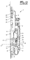
- a locking system for a door with a push-button and key-operated central lock 1 is shown.
- a central lock 1 can be designed as a simple mortise lock and consequently a single lock.
- the illustrated central lock 1 is in the embodiment part of a drive rod lock with multiple locking, in addition, not shown additional locks are provided, which are coupled via drive rods to the central lock, said drive rods are guided behind the lock cuff 2 slidably.
- These provided with a drive rod lock rods are in Fig. 1a only indicated by the reference numeral 3.
- the central lock 1 has a lock case 4, a central bolt 5 and a lock cylinder receptacle 6, in which a lock cylinder 7 is inserted with locking lug 8.
- the central lock in a known manner, not shown, schdrückbare latch and a locknut, also not shown.
- This lock nut is arranged in the recognizable locknut receptacle 9.
- door handle which is mounted at least inside the door.
- the lock nut works in the course of the handle operation not only on the lock latch, but also via a lock chain guided in the lock chain 10 on the central latch 5.
- the lock nut is coupled via a chain driver, not shown, or a similar component to the lock chain 10 and indeed on the arranged in the lock chain inclined guide 11 for the chain drive.
- a pin 12 is arranged on the lock chain 10, which engages in a guide groove 13 as an inclined guide of the central bar 5.
- the bolt lock is plugged with a bearing recess on an integrally formed on the lock box bearing pin.
- the bolt lock 14 is acted upon in the axial direction with a spring 18, which in the embodiment as Compression spring is formed and presses the bolt lock 14 in the axial direction against the lock case 4.
- Lock case means the base plate of the lock case. For this purpose, it is necessary to put the cover, not shown in the figures on the lock case.
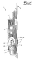
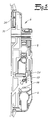
- the invention ensures that the bolt lock 14 always in one of the end position shown in the figures, either in the in Fig. 1a illustrated Endriegelungs ein or in the in Fig. 1b positioned locking position is positioned. This is realized without additional levers and tumblers.
- at least one positive locking element 20, 21 is formed in the bolt lock 14 and at least one positive locking counter-element 19 is formed on the lock case 4, wherein the positive locking element and the positive locking counter element cooperate such that the bolt lock 14 is held on the one hand in the locking position and on the other hand in the unlocked position ,
- a survey 19 and consequently a projection or cam 19 is formed on the lock case 4 and the bottom-side base plate.
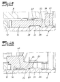
- two corresponding recesses 20, 21 are formed on its the lock box 4 facing bottom, into which engages the projection 19 of the lock case in one hand, the locked position and on the other hand, the unlocked position.
- the cam 19 engages in the locking position in the recess 21 a.
- the bolt lock 14 pivot actively and on schedule by pressing the lock cylinder, wherein the Riegelelsperrre 14 is then lifted in the course of rotation against the force of the spring 18 and thus against the arrow P from the lock box 4.
- This is supported by the fact that the rotational movement of the bolt lock 14 fundamentally preventing flanks of the depressions and elevations are formed as ramped edges as it were ramp-like.
- the elevations 19 and depressions 20, 21 are formed as circular segment sections and are therefore arranged on a circular path, wherein the center of the circular path is formed by the pivot axis 17 of the bolt lock.
- the first recess 20 is formed as a "closed" recess
- the second recess 21 is formed by the special geometry of the bolt lock on one side open, so that only one edge is provided.
- the flank 22 of the recess 20 corresponds to the edge 23 of the elevation 19 and prevents the pivoting of the bolt lock 14 from the unlocked position into the locking position.
- the flank 24 of the second recess 21 corresponds to the edge 25 of the survey and prevents the turning back of the bolt lock 14 from the locking position to the unlocked position.
- a further elevation 26 which has the same mode of operation and which cooperates with two further depressions 27, 28, which have the same function, the depressions 20, 21.
- FIG. 1 shows the operation of the invention by way of example in only one central lock 1, which can also work as a mortise lock. If this central lock 1 is part of a drive rod lock, the indicated drive rods 3 are coupled to the lock chain 10, so that not only the central bolt 5 is moved out or retracted by moving the lock chain 10, but also arranged in the additional latches additional latch. Regardless of the invention, however, there is always a blockage of the lock chain on the bolt lock 14 so that not only the central bolt 5 but also possibly existing additional bolts are secured against pushing back.
Landscapes
- Engineering & Computer Science (AREA)
- Mechanical Engineering (AREA)
- Lock And Its Accessories (AREA)
Applications Claiming Priority (1)
| Application Number | Priority Date | Filing Date | Title |
|---|---|---|---|
| DE202012100133U DE202012100133U1 (de) | 2012-01-13 | 2012-01-13 | Schließanlage |
Publications (2)
| Publication Number | Publication Date |
|---|---|
| EP2615229A2 true EP2615229A2 (fr) | 2013-07-17 |
| EP2615229A3 EP2615229A3 (fr) | 2015-12-02 |
Family
ID=45971654
Family Applications (1)
| Application Number | Title | Priority Date | Filing Date |
|---|---|---|---|
| EP13150389.8A Withdrawn EP2615229A3 (fr) | 2012-01-13 | 2013-01-07 | Installation de fermeture |
Country Status (2)
| Country | Link |
|---|---|
| EP (1) | EP2615229A3 (fr) |
| DE (1) | DE202012100133U1 (fr) |
Cited By (2)
| Publication number | Priority date | Publication date | Assignee | Title |
|---|---|---|---|---|
| DE102017222661A1 (de) | 2017-12-13 | 2019-06-13 | Aug. Winkhaus Gmbh & Co. Kg | Schloss |
| EP3795780A1 (fr) | 2019-09-19 | 2021-03-24 | Aug. Winkhaus GmbH & Co. KG | Serrure à pêne |
Citations (3)
| Publication number | Priority date | Publication date | Assignee | Title |
|---|---|---|---|---|
| DE102004012108A1 (de) | 2004-03-12 | 2005-09-29 | Carl Fuhr Gmbh & Co. Kg | Schließanlage für Türen, Fenster oder dergleichen, insbesondere Treibstangenschloss mit Panikfunktion und Mehrpunktverriegelung |
| DE202007016091U1 (de) | 2007-11-17 | 2008-03-06 | Carl Fuhr Gmbh & Co. Kg | Treibstangenschloss |
| DE102006059568A1 (de) | 2006-12-16 | 2008-06-19 | Carl Fuhr Gmbh & Co. Kg | Schließanlage für Türen, Fenster oder dergleichen, insbesondere Treibstangenschloss mit Panikfunktion und Mehrpunktverriegelung |
Family Cites Families (4)
| Publication number | Priority date | Publication date | Assignee | Title |
|---|---|---|---|---|
| DE29920508U1 (de) * | 1999-11-23 | 2000-02-24 | Gretsch-Unitas GmbH Baubeschläge, 71254 Ditzingen | Treibstangenschloss |
| DE10147782B4 (de) * | 2001-09-27 | 2016-09-22 | Gretsch-Unitas GmbH Baubeschläge | Betätigungsgetriebe, insbesondere Schloss für einen Treibstangenbeschlag sowie Treibstangenbeschlag mit einem solchen Betätigungsgetriebe |
| NZ521338A (en) * | 2002-09-12 | 2005-02-25 | Assa Abloy Financial Services | A lock mechanism |
| ATE446428T1 (de) * | 2003-02-25 | 2009-11-15 | Roto Frank Ag | Getriebe für ein fenster oder dergleichen mit integrierter rastung, insbesondere spreizgetriebe |
-
2012
- 2012-01-13 DE DE202012100133U patent/DE202012100133U1/de not_active Expired - Lifetime
-
2013
- 2013-01-07 EP EP13150389.8A patent/EP2615229A3/fr not_active Withdrawn
Patent Citations (3)
| Publication number | Priority date | Publication date | Assignee | Title |
|---|---|---|---|---|
| DE102004012108A1 (de) | 2004-03-12 | 2005-09-29 | Carl Fuhr Gmbh & Co. Kg | Schließanlage für Türen, Fenster oder dergleichen, insbesondere Treibstangenschloss mit Panikfunktion und Mehrpunktverriegelung |
| DE102006059568A1 (de) | 2006-12-16 | 2008-06-19 | Carl Fuhr Gmbh & Co. Kg | Schließanlage für Türen, Fenster oder dergleichen, insbesondere Treibstangenschloss mit Panikfunktion und Mehrpunktverriegelung |
| DE202007016091U1 (de) | 2007-11-17 | 2008-03-06 | Carl Fuhr Gmbh & Co. Kg | Treibstangenschloss |
Cited By (3)
| Publication number | Priority date | Publication date | Assignee | Title |
|---|---|---|---|---|
| DE102017222661A1 (de) | 2017-12-13 | 2019-06-13 | Aug. Winkhaus Gmbh & Co. Kg | Schloss |
| EP3498943A1 (fr) | 2017-12-13 | 2019-06-19 | Aug. Winkhaus GmbH & Co. KG | Serrure |
| EP3795780A1 (fr) | 2019-09-19 | 2021-03-24 | Aug. Winkhaus GmbH & Co. KG | Serrure à pêne |
Also Published As
| Publication number | Publication date |
|---|---|
| DE202012100133U1 (de) | 2012-03-16 |
| EP2615229A3 (fr) | 2015-12-02 |
Similar Documents
| Publication | Publication Date | Title |
|---|---|---|
| EP1932989B1 (fr) | Système de fermeture pour portes, fenêtres ou analogues, en particulier crémone-serrure à fonction d'urgence et de verrouillage à plusieurs points | |
| EP2951368B1 (fr) | Serrure anti-panique | |
| DE3844849C2 (de) | Treibstangenverschluß | |
| DE102006059568A1 (de) | Schließanlage für Türen, Fenster oder dergleichen, insbesondere Treibstangenschloss mit Panikfunktion und Mehrpunktverriegelung | |
| DE102004012108B4 (de) | Treibstangenschloss für Türen, Fenster oder dergleichen mit Panikfunktion und Mehrpunktverriegelung | |
| EP3016844B1 (fr) | Ensemble serrure pour porte-bagages | |
| DE4303400C2 (de) | Treibstangenschloss mit Abdicht- und Sicherheitsfunktion ß | |
| EP3406832B1 (fr) | Gâche pour une serrure antipanique | |
| EP2441905B1 (fr) | Serrure | |
| DE4114007C2 (de) | Treibstangenverschluß | |
| EP2520746B1 (fr) | Serrure actionnée de manière électrique | |
| EP2339096B1 (fr) | Serrure à crémone dotée d'une fonction anti-panique et d'un verrouillage multiple | |
| EP0471976B1 (fr) | Crémone | |
| EP2820208B1 (fr) | Serrure | |
| EP2405085B1 (fr) | Serrure à crémone dotée d'une sécurité améliorée | |
| DE102015000606A1 (de) | Verriegelungsvorrichtung für einen schwenkbar gelagerten Flügel | |
| EP2615229A2 (fr) | Installation de fermeture | |
| DE102008015655A1 (de) | Panikschloss | |
| EP2060714A2 (fr) | Crémone-serrure | |
| EP3018274B1 (fr) | Contre-serrure d'une serrure a espagnolette d'une porte a deux battants | |
| EP0974721B1 (fr) | Serrure à plusieurs pênes | |
| EP2738324B1 (fr) | Serrure dotée d'une unité de rotation débloquable | |
| EP4116529A1 (fr) | Unité de verrouillage | |
| EP0439478B1 (fr) | Serrure a verrouillage automatique | |
| DE10318707B4 (de) | Sicherheitseinrichtung |
Legal Events
| Date | Code | Title | Description |
|---|---|---|---|
| PUAI | Public reference made under article 153(3) epc to a published international application that has entered the european phase |
Free format text: ORIGINAL CODE: 0009012 |
|
| AK | Designated contracting states |
Kind code of ref document: A2 Designated state(s): AL AT BE BG CH CY CZ DE DK EE ES FI FR GB GR HR HU IE IS IT LI LT LU LV MC MK MT NL NO PL PT RO RS SE SI SK SM TR |
|
| AX | Request for extension of the european patent |
Extension state: BA ME |
|
| PUAL | Search report despatched |
Free format text: ORIGINAL CODE: 0009013 |
|
| AK | Designated contracting states |
Kind code of ref document: A3 Designated state(s): AL AT BE BG CH CY CZ DE DK EE ES FI FR GB GR HR HU IE IS IT LI LT LU LV MC MK MT NL NO PL PT RO RS SE SI SK SM TR |
|
| AX | Request for extension of the european patent |
Extension state: BA ME |
|
| RIC1 | Information provided on ipc code assigned before grant |
Ipc: E05B 59/00 20060101ALI20151028BHEP Ipc: E05B 15/00 20060101ALI20151028BHEP Ipc: E05B 9/02 20060101ALI20151028BHEP Ipc: E05C 9/02 20060101AFI20151028BHEP Ipc: E05B 63/00 20060101ALI20151028BHEP |
|
| STAA | Information on the status of an ep patent application or granted ep patent |
Free format text: STATUS: THE APPLICATION IS DEEMED TO BE WITHDRAWN |
|
| 18D | Application deemed to be withdrawn |
Effective date: 20160603 |