EP2615263A2 - Diffuseur pour une turbine à gaz - Google Patents
Diffuseur pour une turbine à gaz Download PDFInfo
- Publication number
- EP2615263A2 EP2615263A2 EP13150586.9A EP13150586A EP2615263A2 EP 2615263 A2 EP2615263 A2 EP 2615263A2 EP 13150586 A EP13150586 A EP 13150586A EP 2615263 A2 EP2615263 A2 EP 2615263A2
- Authority
- EP
- European Patent Office
- Prior art keywords
- diffuser
- inlet
- outlet
- wall
- inner barrel
- Prior art date
- Legal status (The legal status is an assumption and is not a legal conclusion. Google has not performed a legal analysis and makes no representation as to the accuracy of the status listed.)
- Withdrawn
Links
- 230000008878 coupling Effects 0.000 claims abstract description 13
- 238000010168 coupling process Methods 0.000 claims abstract description 13
- 238000005859 coupling reaction Methods 0.000 claims abstract description 13
- 238000000926 separation method Methods 0.000 description 8
- 238000011144 upstream manufacturing Methods 0.000 description 5
- 238000013459 approach Methods 0.000 description 2
- 238000009792 diffusion process Methods 0.000 description 2
- 230000001747 exhibiting effect Effects 0.000 description 2
- 230000003068 static effect Effects 0.000 description 2
- 230000004075 alteration Effects 0.000 description 1
- 238000010276 construction Methods 0.000 description 1
- 230000003247 decreasing effect Effects 0.000 description 1
- 239000012530 fluid Substances 0.000 description 1
- 230000006872 improvement Effects 0.000 description 1
- 238000011084 recovery Methods 0.000 description 1
- 230000009467 reduction Effects 0.000 description 1
- 230000003584 silencer Effects 0.000 description 1
- 238000006467 substitution reaction Methods 0.000 description 1
Images

Classifications
-
- F—MECHANICAL ENGINEERING; LIGHTING; HEATING; WEAPONS; BLASTING
- F01—MACHINES OR ENGINES IN GENERAL; ENGINE PLANTS IN GENERAL; STEAM ENGINES
- F01D—NON-POSITIVE DISPLACEMENT MACHINES OR ENGINES, e.g. STEAM TURBINES
- F01D25/00—Component parts, details, or accessories, not provided for in, or of interest apart from, other groups
- F01D25/30—Exhaust heads, chambers, or the like
Definitions
- the subject matter disclosed herein relates generally to turbines and, in particular, to diffusers for use with gas turbines and steam turbines.
- Typical gas turbines include a diffuser cone, or diffuser, coupled to the last stage bucket of the rotor.
- the diffuser serves, generally, to increase static pressure of the exhaust gas by decreasing the kinetic energy of the exhaust gas. Generally, this may be achieved by increasing the cross-sectional area of the diffuser in the direction of exhaust gas flow.
- gas turbines are not operated at full load, but are designed for efficiency under such a full load. Therefore, part load performance efficiency is sacrificed, based on the full load design. Such inefficiencies are due, at least in part, to flow separation on the diffuser inner barrel, leading to tip strong flow profiles. Other factors, such as operation of the last stage of the turbine, may influence the flow profile. Additionally, flow passing over a center body of the diffuser generates large vortices that result in yet further system inefficiency.
- a diffuser for a gas turbine includes an inlet adapted for coupling to the gas turbine.
- the diffuser also includes at least one outlet located proximate a diffuser end, wherein the diffuser end is located downstream of the inlet.
- the diffuser further includes an outer wall and an inner barrel extending substantially to the diffuser end.
- an exhaust gas diffuser includes an inlet and an outlet.
- the exhaust gas diffuser also includes an inner barrel extending from substantially the inlet to substantially the outlet.
- the diffuser further includes an outer wall radially spaced apart from the inner barrel, wherein the outer wall and the inner barrel define a varying radius along a length of the diffuser between the inlet and the outlet.
- a gas turbine includes a turbine casing that surrounds a portion of the gas turbine.
- the gas turbine also includes an exhaust gas diffuser coupled to the turbine casing.
- the diffuser includes an inlet adapted for coupling to the gas turbine, an outer wall, an inner barrel and a diffuser end downstream from the inlet, the inner barrel extending substantially to the diffuser end.
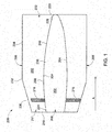
- FIG. 1 illustrates one aspect of a diffuser 200 according to one embodiment of the present invention.
- exhaust gas from the gas turbine flows through the diffuser 200 in the direction shown by arrow A.
- an object is "downstream” of another object or location if it is displaced from it in the direction of arrow A and is “upstream” if it is displaced from it in a direction opposite of arrow A.
- the diffuser 200 includes an inner barrel 202 that includes an inner wall 204 that forms an inner chamber 208 through which a portion of a rotor may pass.
- the diffuser 200 includes an inlet 211 located proximate a diffuser entry end 210 and an outlet 220 located proximate a diffuser exit end 222.
- the inlet 211 may be coupled to a turbine, while the outlet 220 may be coupled to an adjacent object, such as a silencer.
- the diffuser also includes an outer wall 206 radially spaced from the inner wall 204 of the inner barrel 202. The area between the inner wall 204 and the outer wall 206 allows fluid or gas to flow downstream therethrough from the inlet 211 to the outlet 220 of the diffuser 200.
- the diffuser 200 may also include one or more struts 216 formed between the inner wall 204 and the outer wall 206.
- the strut 216 serves to hold the inner wall 204 and the outer wall 206 in a fixed relationship to one another, as well as providing bearing support.
- the number of struts 216 is variable and commonly ranges from about four to about ten.
- the inner wall 204 of the inner barrel 202 extends from the inlet 211, or diffuser entry end 210, to the outlet 220, or diffuser exit end 222.
- the inner barrel 202, and hence the inner wall 204 includes a first end 224 located proximate the inlet 211 and a second end 226 located proximate the outlet 220 and may take on numerous longitudinal contours as the inner barrel 202 extends from the first end 224 to the second end 226.
- the inner barrel 202 may slightly curve continuously from the first end 224 to the second end 226, may curve slightly for only portions between the first end 224 and the second end 226, may extend in a substantially straight direction, or may comprise segmented portions, where the overall longitudinal direction of the inner barrel 202 comprises any combination of the curvilinear paths described above. Irrespective of the shape of the inner barrel 202, and more particularly the inner wall 204, the inner barrel 202 and inner wall 204 extend to the diffuser outlet 220 or diffuser exit 222.
- the outer wall 206 includes a first portion 230 that extends from the inlet 211, or diffuser entry end 210, in a substantially downstream direction, as well as in a direction away from the inner wall 204.
- the sloping curvilinear direction of first portion 230 of the outer wall 206 terminates at an outer radius location 232.
- the outer wall 206 also includes a second portion 234 that extends from the outer radius location 232 in a substantially downstream direction to the outlet 220, or diffuser exit end 222.
- the first portion 230 of the outer wall 206 angles away from the inner wall 204 more substantially than the second portion of the outer wall 206, with the outer radius location 232 being located further upstream than a longitudinal midpoint 236 of the inner barrel 202.
- the portion of the inner barrel 202 located upstream of the longitudinal midpoint 236 is an inlet portion 238, while the portion of the inner barrel located downstream of the longitudinal midpoint 236 is an outlet portion 240. Therefore, the outer wall 206 is pushed to an outer radius further upstream than conventional diffuser outer wall constructions.
- FIG. 2 shows a flow path profile in diffuser 200 shown in FIG. 1 .
- the flow profile for the diffuser 200 of FIG. 1 is strong throughout the entire radial area of the diffuser 200, even along the inner wall 204.
- the diffuser 200 reduces flow separation, thereby improving diffuser performance over a diffuser flow profile exhibiting flow separation, as shown in FIG. 3 .
- the introduction of secondary air flow may be injected into the diffuser 200.
- Such a secondary air flow into the diffuser 200 and thereby a main diffuser flow alters overall flow by energizing a shear layer that is formed between the main flow and the inner wall 204 and/or outer wall 206, causing a delay of the flow separation itself.
- the main flow widens and a larger static pressure recovery is achieved.
- a flow manipulation device such as a pump
- the inner wall 204 of the inner barrel 202 includes one or more actuator openings and one or more suction openings that are located downstream of the one or more actuator openings.
- the suction opening allows common weak flow that passes directly over the inner wall 204 to enter the inner barrel 202 and pass through the flow manipulating device with sufficient force to exit the actuating opening in a manner that manipulates the flow profile of the diffuser 200.
- the manipulation of flow reduces flow separation, thereby increasing diffusion area.
- diffuser 200 flow path is controlled by focusing the diffusion gradient near the region of high velocity and radially redistributing the flow.
- the inner barrel 202 extends to the relative outlet 220 of the diffuser 200.
- an outer wall 206 of the diffuser 200 extends radially away from the inner barrel 202 at a rapid rate, starting upstream at the relative inlet 211 of the diffuser 200. The result is a reduction in loss producing vortices associated with wake and a significant improvement in diffuser performance and thereby system heat rate gain. While the invention has been described in detail in connection with only a limited number of embodiments, it should be readily understood that the invention is not limited to such disclosed embodiments.
Landscapes
- Engineering & Computer Science (AREA)
- Mechanical Engineering (AREA)
- General Engineering & Computer Science (AREA)
- Structures Of Non-Positive Displacement Pumps (AREA)
- Supercharger (AREA)
Applications Claiming Priority (1)
| Application Number | Priority Date | Filing Date | Title |
|---|---|---|---|
| US13/350,313 US20130180246A1 (en) | 2012-01-13 | 2012-01-13 | Diffuser for a gas turbine |
Publications (1)
| Publication Number | Publication Date |
|---|---|
| EP2615263A2 true EP2615263A2 (fr) | 2013-07-17 |
Family
ID=47631262
Family Applications (1)
| Application Number | Title | Priority Date | Filing Date |
|---|---|---|---|
| EP13150586.9A Withdrawn EP2615263A2 (fr) | 2012-01-13 | 2013-01-09 | Diffuseur pour une turbine à gaz |
Country Status (5)
| Country | Link |
|---|---|
| US (1) | US20130180246A1 (fr) |
| EP (1) | EP2615263A2 (fr) |
| JP (1) | JP2013144979A (fr) |
| CN (1) | CN103206273A (fr) |
| RU (1) | RU2013100408A (fr) |
Families Citing this family (4)
| Publication number | Priority date | Publication date | Assignee | Title |
|---|---|---|---|---|
| JP6033154B2 (ja) * | 2013-03-29 | 2016-11-30 | 三菱重工業株式会社 | 軸流回転機械、及びディフューザ |
| EP3054086B1 (fr) * | 2015-02-05 | 2017-09-13 | General Electric Technology GmbH | Configuration de diffuseur de turbine à vapeur |
| US10563543B2 (en) | 2016-05-31 | 2020-02-18 | General Electric Company | Exhaust diffuser |
| US12560103B2 (en) * | 2023-12-04 | 2026-02-24 | Pratt & Whitney Canada Corp. | Rear-cone exhaust duct for additive manufacturing |
Family Cites Families (7)
| Publication number | Priority date | Publication date | Assignee | Title |
|---|---|---|---|---|
| US2674845A (en) * | 1951-05-02 | 1954-04-13 | Walter D Pouchot | Diffuser apparatus with boundary layer control |
| US3625630A (en) * | 1970-03-27 | 1971-12-07 | Caterpillar Tractor Co | Axial flow diffuser |
| JP3070401B2 (ja) * | 1994-08-23 | 2000-07-31 | 株式会社日立製作所 | ガスタービン排気構造 |
| US5632142A (en) * | 1995-02-15 | 1997-05-27 | Surette; Robert G. | Stationary gas turbine power system and related method |
| US7272930B2 (en) * | 2003-09-25 | 2007-09-25 | Siemens Power Generation | Exhaust diffuser assembly with tunable velocity profile |
| US7493769B2 (en) * | 2005-10-25 | 2009-02-24 | General Electric Company | Assembly and method for cooling rear bearing and exhaust frame of gas turbine |
| US20110088379A1 (en) * | 2009-10-15 | 2011-04-21 | General Electric Company | Exhaust gas diffuser |
-
2012
- 2012-01-13 US US13/350,313 patent/US20130180246A1/en not_active Abandoned
-
2013
- 2013-01-08 JP JP2013000768A patent/JP2013144979A/ja active Pending
- 2013-01-09 EP EP13150586.9A patent/EP2615263A2/fr not_active Withdrawn
- 2013-01-10 RU RU2013100408/06A patent/RU2013100408A/ru not_active Application Discontinuation
- 2013-01-11 CN CN2013100100984A patent/CN103206273A/zh active Pending
Non-Patent Citations (1)
| Title |
|---|
| None |
Also Published As
| Publication number | Publication date |
|---|---|
| US20130180246A1 (en) | 2013-07-18 |
| JP2013144979A (ja) | 2013-07-25 |
| CN103206273A (zh) | 2013-07-17 |
| RU2013100408A (ru) | 2014-07-20 |
Similar Documents
| Publication | Publication Date | Title |
|---|---|---|
| JP6017755B2 (ja) | 排気ガスディフューザ | |
| US8721273B2 (en) | Ring diffuser for an axial turbomachine | |
| US20110052373A1 (en) | High-turning diffuser strut with flow cross-over slots | |
| US20160115971A1 (en) | Diffuser pipe with splitter vane | |
| CN102906429A (zh) | 用于产生一串压缩机叶片上游的旋涡的旋涡发生器 | |
| EP2341215A2 (fr) | Diffuseur creux de guidage de vapeur doté d'une récupération de pression améliorée | |
| EP2615263A2 (fr) | Diffuseur pour une turbine à gaz | |
| US8500399B2 (en) | Method and apparatus for enhancing compressor performance | |
| US8591184B2 (en) | Hub flowpath contour | |
| US8628297B2 (en) | Tip flowpath contour | |
| EP2578815A2 (fr) | Diffuseur de gaz d'échappement | |
| US8870532B2 (en) | Exhaust hood diffuser | |
| KR20170029525A (ko) | 배기가스 터보차저의 터빈의 배출영역 | |
| US10612421B2 (en) | Gas turbine exhaust assembly | |
| CN102822534B (zh) | 压气机以及装配有至少一个压气机和排气系统的发动机 | |
| EP2615262A2 (fr) | Diffuseur comportant un actionnement fluidique | |
| EP2674572A2 (fr) | Diffuseur d'échappement de turbine | |
| CN103511008B (zh) | 用于涡轮机的扩散器 | |
| US9388710B2 (en) | Exhaust diffuser arrangement for a turbine system and method of redirecting a flow | |
| US20180258778A1 (en) | Non-axially symmetric transition ducts for combustors |
Legal Events
| Date | Code | Title | Description |
|---|---|---|---|
| PUAI | Public reference made under article 153(3) epc to a published international application that has entered the european phase |
Free format text: ORIGINAL CODE: 0009012 |
|
| AK | Designated contracting states |
Kind code of ref document: A2 Designated state(s): AL AT BE BG CH CY CZ DE DK EE ES FI FR GB GR HR HU IE IS IT LI LT LU LV MC MK MT NL NO PL PT RO RS SE SI SK SM TR |
|
| AX | Request for extension of the european patent |
Extension state: BA ME |
|
| STAA | Information on the status of an ep patent application or granted ep patent |
Free format text: STATUS: THE APPLICATION IS DEEMED TO BE WITHDRAWN |
|
| 18D | Application deemed to be withdrawn |
Effective date: 20160802 |