EP2615367A1 - Eclairage - Google Patents
Eclairage Download PDFInfo
- Publication number
- EP2615367A1 EP2615367A1 EP13000126.6A EP13000126A EP2615367A1 EP 2615367 A1 EP2615367 A1 EP 2615367A1 EP 13000126 A EP13000126 A EP 13000126A EP 2615367 A1 EP2615367 A1 EP 2615367A1
- Authority
- EP
- European Patent Office
- Prior art keywords
- light
- lens
- exit surface
- entry surfaces
- luminaire according
- Prior art date
- Legal status (The legal status is an assumption and is not a legal conclusion. Google has not performed a legal analysis and makes no representation as to the accuracy of the status listed.)
- Withdrawn
Links
Images


Classifications
-
- F—MECHANICAL ENGINEERING; LIGHTING; HEATING; WEAPONS; BLASTING
- F21—LIGHTING
- F21V—FUNCTIONAL FEATURES OR DETAILS OF LIGHTING DEVICES OR SYSTEMS THEREOF; STRUCTURAL COMBINATIONS OF LIGHTING DEVICES WITH OTHER ARTICLES, NOT OTHERWISE PROVIDED FOR
- F21V5/00—Refractors for light sources
- F21V5/04—Refractors for light sources of lens shape
-
- F—MECHANICAL ENGINEERING; LIGHTING; HEATING; WEAPONS; BLASTING
- F21—LIGHTING
- F21V—FUNCTIONAL FEATURES OR DETAILS OF LIGHTING DEVICES OR SYSTEMS THEREOF; STRUCTURAL COMBINATIONS OF LIGHTING DEVICES WITH OTHER ARTICLES, NOT OTHERWISE PROVIDED FOR
- F21V5/00—Refractors for light sources
- F21V5/007—Array of lenses or refractors for a cluster of light sources, e.g. for arrangement of multiple light sources in one plane
-
- F—MECHANICAL ENGINEERING; LIGHTING; HEATING; WEAPONS; BLASTING
- F21—LIGHTING
- F21V—FUNCTIONAL FEATURES OR DETAILS OF LIGHTING DEVICES OR SYSTEMS THEREOF; STRUCTURAL COMBINATIONS OF LIGHTING DEVICES WITH OTHER ARTICLES, NOT OTHERWISE PROVIDED FOR
- F21V5/00—Refractors for light sources
- F21V5/08—Refractors for light sources producing an asymmetric light distribution
-
- G—PHYSICS
- G02—OPTICS
- G02B—OPTICAL ELEMENTS, SYSTEMS OR APPARATUS
- G02B19/00—Condensers, e.g. light collectors or similar non-imaging optics
- G02B19/0004—Condensers, e.g. light collectors or similar non-imaging optics characterised by the optical means employed
- G02B19/0009—Condensers, e.g. light collectors or similar non-imaging optics characterised by the optical means employed having refractive surfaces only
-
- G—PHYSICS
- G02—OPTICS
- G02B—OPTICAL ELEMENTS, SYSTEMS OR APPARATUS
- G02B19/00—Condensers, e.g. light collectors or similar non-imaging optics
- G02B19/0033—Condensers, e.g. light collectors or similar non-imaging optics characterised by the use
- G02B19/0047—Condensers, e.g. light collectors or similar non-imaging optics characterised by the use for use with a light source
- G02B19/0061—Condensers, e.g. light collectors or similar non-imaging optics characterised by the use for use with a light source the light source comprising a LED
- G02B19/0066—Condensers, e.g. light collectors or similar non-imaging optics characterised by the use for use with a light source the light source comprising a LED in the form of an LED array
-
- F—MECHANICAL ENGINEERING; LIGHTING; HEATING; WEAPONS; BLASTING
- F21—LIGHTING
- F21V—FUNCTIONAL FEATURES OR DETAILS OF LIGHTING DEVICES OR SYSTEMS THEREOF; STRUCTURAL COMBINATIONS OF LIGHTING DEVICES WITH OTHER ARTICLES, NOT OTHERWISE PROVIDED FOR
- F21V23/00—Arrangement of electric circuit elements in or on lighting devices
- F21V23/04—Arrangement of electric circuit elements in or on lighting devices the elements being switches
-
- F—MECHANICAL ENGINEERING; LIGHTING; HEATING; WEAPONS; BLASTING
- F21—LIGHTING
- F21W—INDEXING SCHEME ASSOCIATED WITH SUBCLASSES F21K, F21L, F21S and F21V, RELATING TO USES OR APPLICATIONS OF LIGHTING DEVICES OR SYSTEMS
- F21W2131/00—Use or application of lighting devices or systems not provided for in codes F21W2102/00-F21W2121/00
- F21W2131/10—Outdoor lighting
-
- F—MECHANICAL ENGINEERING; LIGHTING; HEATING; WEAPONS; BLASTING
- F21—LIGHTING
- F21W—INDEXING SCHEME ASSOCIATED WITH SUBCLASSES F21K, F21L, F21S and F21V, RELATING TO USES OR APPLICATIONS OF LIGHTING DEVICES OR SYSTEMS
- F21W2131/00—Use or application of lighting devices or systems not provided for in codes F21W2102/00-F21W2121/00
- F21W2131/10—Outdoor lighting
- F21W2131/103—Outdoor lighting of streets or roads
-
- F—MECHANICAL ENGINEERING; LIGHTING; HEATING; WEAPONS; BLASTING
- F21—LIGHTING
- F21Y—INDEXING SCHEME ASSOCIATED WITH SUBCLASSES F21K, F21L, F21S and F21V, RELATING TO THE FORM OR THE KIND OF THE LIGHT SOURCES OR OF THE COLOUR OF THE LIGHT EMITTED
- F21Y2113/00—Combination of light sources
- F21Y2113/10—Combination of light sources of different colours
- F21Y2113/13—Combination of light sources of different colours comprising an assembly of point-like light sources
-
- F—MECHANICAL ENGINEERING; LIGHTING; HEATING; WEAPONS; BLASTING
- F21—LIGHTING
- F21Y—INDEXING SCHEME ASSOCIATED WITH SUBCLASSES F21K, F21L, F21S and F21V, RELATING TO THE FORM OR THE KIND OF THE LIGHT SOURCES OR OF THE COLOUR OF THE LIGHT EMITTED
- F21Y2115/00—Light-generating elements of semiconductor light sources
- F21Y2115/10—Light-emitting diodes [LED]
Definitions
- the lens exit surface may be ellipsoidal, wherein preferably a short major axis of the ellipsoid defined by the light exit surface is perpendicular to the lens exit surface in which the light entry surfaces are formed, while a long major axis of said ellipsoid is parallel to may be aligned with said lens base surface.
- the said light entry surfaces which are assigned to the different light sources are advantageously themselves asymmetrically contoured in each case, but may nevertheless be arranged symmetrically with respect to a plane of symmetry of the light exit surface and / or symmetrically with respect to a main axis of the light exit surface.
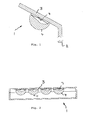
- a plurality of lenses 4 may be arranged side by side evenly spaced from each other, wherein the respective lenses 4 may be aligned parallel to each other with an at least approximately planar lens base surface 6, in particular on a mounting surface of the light carrier 3 may be attached.
- the light exit surface 5 may be formed symmetrically with respect to two planes of symmetry which are perpendicular to each other, wherein advantageously one of the two planes of symmetry passes through the light sources 7 and is perpendicular to the lens base surface 6, while a second plane of symmetry between can run the two light sources 7 and is also perpendicular to said lens base surface 6.
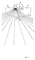
- the two symmetry planes mentioned on the one hand form the plane of the drawing Fig. 3 and on the other hand, a plane parallel to the plane of the Fig. 2 , The second-mentioned symmetry plane can perpendicular to the plane of the Fig. 3 run through the registered there axis 10.
- the two light entry surfaces 8 are asymmetrically contoured and shaped in such a way that, in interaction with the light exit surface 5, the light beams of the two light sources 7 uniformly overlap outside the lens 4 in the intended area to be illuminated space and there produce approximately identical light intensity distributions.
- the light intensity distributions generated by the light beams of the light sources 7 can deviate even more or less slightly from each other, but these deviations are lost until the area to be illuminated is illuminated as intended.
- the named as intended Illuminated space can vary depending on the lighting task, but is usually 1 to 15 m, in particular about 2 to 10 m from the respective lens 4 spaced.
- the intended area to be illuminated is approximately 0 to 2 m above the floor surface.
- the light beams of the plurality of light sources 7 which are associated with a lens 4 produce substantially the same light intensity distributions, so that the light intensity distribution produced by a lens hardly or hardly changes if either one of them 7 light sources fails.
- the lens - for example, in the intended range to be illuminated by the lamp, especially in the so-called far field of the lamp, which can begin at about 5 times or 10 times the luminaire or lens diameter - a flat surface, for example, perpendicular to Main beam direction in the light cone of the lamp 1, regardless of which and how many light sources 7 are turned on the surface always the same area illuminated or irradiated, on this piece of surface, the brightness and the light intensities are always the same. Only the brightness level or light intensity level and the color temperature varies depending on the switched-light source or depending on the number of light sources and their nature.
- Corresponding uniform light distributions regardless of the light source or in each case switched on, are also exhibited on non-planar surfaces, which are held with said minimum distance from the lens in the light or radiation range of the lamp.
- the interaction of the light entry surfaces with the common light exit surface of the lens produces for the beams of light coming from the plurality of light sources these substantially identical light distributions.
- the light entry surfaces 6 may each be asymmetrically contoured, wherein elongated, narrow contoured depressions may be provided as light entry surfaces whose longitudinal axes are transverse can extend to the long main axis of the ellipsoidal light exit surface 5, cf.
- Fig. 6 Irrespective of the individually asymmetrical design of the respective light entry surface 8, the light entry surfaces 8 of a lens 4 can be arranged symmetrically with respect to a plane of symmetry of the light exit surface 5, cf. Fig. 6 ,
Landscapes
- Engineering & Computer Science (AREA)
- General Engineering & Computer Science (AREA)
- Physics & Mathematics (AREA)
- General Physics & Mathematics (AREA)
- Optics & Photonics (AREA)
- Non-Portable Lighting Devices Or Systems Thereof (AREA)
Applications Claiming Priority (1)
| Application Number | Priority Date | Filing Date | Title |
|---|---|---|---|
| DE102012000388A DE102012000388A1 (de) | 2012-01-11 | 2012-01-11 | Leuchte |
Publications (1)
| Publication Number | Publication Date |
|---|---|
| EP2615367A1 true EP2615367A1 (fr) | 2013-07-17 |
Family
ID=47559270
Family Applications (1)
| Application Number | Title | Priority Date | Filing Date |
|---|---|---|---|
| EP13000126.6A Withdrawn EP2615367A1 (fr) | 2012-01-11 | 2013-01-10 | Eclairage |
Country Status (2)
| Country | Link |
|---|---|
| EP (1) | EP2615367A1 (fr) |
| DE (1) | DE102012000388A1 (fr) |
Cited By (1)
| Publication number | Priority date | Publication date | Assignee | Title |
|---|---|---|---|---|
| WO2018114769A1 (fr) * | 2016-12-19 | 2018-06-28 | Osram Opto Semiconductors Gmbh | Composant optoélectronique |
Citations (7)
| Publication number | Priority date | Publication date | Assignee | Title |
|---|---|---|---|---|
| WO2006072397A1 (fr) * | 2005-01-05 | 2006-07-13 | Hansa Metallwerke Ag | Appareil de robinetterie comprenant un ensemble de plusieurs sources de lumiere |
| US20070159832A1 (en) * | 2006-01-12 | 2007-07-12 | Samsung Corning Co., Ltd. | Backlight unit and light source for use in same |
| WO2008122941A1 (fr) * | 2007-04-05 | 2008-10-16 | Koninklijke Philips Electronics N.V. | Dispositif de mise en forme de faisceaux lumineux |
| DE102007043192A1 (de) * | 2007-09-11 | 2009-03-12 | Osram Opto Semiconductors Gmbh | Leuchtdioden-Modul |
| US20100165640A1 (en) * | 2008-12-25 | 2010-07-01 | Lin Lung-Sheng | Optical member of lighting device |
| US20110221020A1 (en) * | 2010-03-10 | 2011-09-15 | Fujifilm Corporation | Wafer lens array and method for manufacturing the same |
| WO2012085853A1 (fr) * | 2010-12-22 | 2012-06-28 | Koninklijke Philips Electronics N.V. | Dispositif d'éclairage à modificateur de lumière produite |
Family Cites Families (1)
| Publication number | Priority date | Publication date | Assignee | Title |
|---|---|---|---|---|
| WO2011154470A1 (fr) * | 2010-06-09 | 2011-12-15 | Automotive Lighting Reutlingen Gmbh | Accessoire optique constitué d'un matériau transparent pour la focalisation de lumière, ensemble de lentilles comportant au moins un tel accessoire optique, et module de lumière doté d'un tel ensemble de lentilles |
-
2012
- 2012-01-11 DE DE102012000388A patent/DE102012000388A1/de not_active Withdrawn
-
2013
- 2013-01-10 EP EP13000126.6A patent/EP2615367A1/fr not_active Withdrawn
Patent Citations (7)
| Publication number | Priority date | Publication date | Assignee | Title |
|---|---|---|---|---|
| WO2006072397A1 (fr) * | 2005-01-05 | 2006-07-13 | Hansa Metallwerke Ag | Appareil de robinetterie comprenant un ensemble de plusieurs sources de lumiere |
| US20070159832A1 (en) * | 2006-01-12 | 2007-07-12 | Samsung Corning Co., Ltd. | Backlight unit and light source for use in same |
| WO2008122941A1 (fr) * | 2007-04-05 | 2008-10-16 | Koninklijke Philips Electronics N.V. | Dispositif de mise en forme de faisceaux lumineux |
| DE102007043192A1 (de) * | 2007-09-11 | 2009-03-12 | Osram Opto Semiconductors Gmbh | Leuchtdioden-Modul |
| US20100165640A1 (en) * | 2008-12-25 | 2010-07-01 | Lin Lung-Sheng | Optical member of lighting device |
| US20110221020A1 (en) * | 2010-03-10 | 2011-09-15 | Fujifilm Corporation | Wafer lens array and method for manufacturing the same |
| WO2012085853A1 (fr) * | 2010-12-22 | 2012-06-28 | Koninklijke Philips Electronics N.V. | Dispositif d'éclairage à modificateur de lumière produite |
Cited By (2)
| Publication number | Priority date | Publication date | Assignee | Title |
|---|---|---|---|---|
| WO2018114769A1 (fr) * | 2016-12-19 | 2018-06-28 | Osram Opto Semiconductors Gmbh | Composant optoélectronique |
| US11233089B2 (en) | 2016-12-19 | 2022-01-25 | Osram Oled Gmbh | Optoelectronic component |
Also Published As
| Publication number | Publication date |
|---|---|
| DE102012000388A1 (de) | 2013-07-11 |
Similar Documents
| Publication | Publication Date | Title |
|---|---|---|
| EP2754948B1 (fr) | Module lumineux pour un phare de véhicule automobile conçu pour produire des distributions lumineuses en forme de bande | |
| EP3494343B1 (fr) | Phare de véhicule | |
| DE102008048765B4 (de) | Beleuchtungsvorrichtung für Kraftfahrzeuge | |
| DE102013217843A1 (de) | Projektionsoptik zum Einsatz in einem LED-Modul eines Kraftfahrzeugscheinwerfers, sowie LED-Modul und Kraftfahrzeugscheinwerfer mit einer solchen Projektionsoptik | |
| DE102008014317A1 (de) | Leuchte mit getrennten Leuchtmitteln für Direktbeleuchtung und Indirektbeleuchtung | |
| DE102017115899B4 (de) | Kraftfahrzeugleuchte und Kraftfahrzeugscheinwerfer mit einer solchen Leuchte | |
| EP3012521B1 (fr) | Éclairage pour un vehicule automobile | |
| EP2984397B1 (fr) | Unité d'éclairage pour projecteur de véhicule | |
| AT510931A1 (de) | Fahrzeugscheinwerfer mit led-lichtmodul | |
| DE102012107676A1 (de) | Optikkörper für eine Fahrzeugleuchte | |
| EP2924345B1 (fr) | Luminaires avec distribution de lumière dissymétrique | |
| EP2770247A2 (fr) | Phare de véhicule automobile ayant une apparence lumineuse claire homogène | |
| DE102013202957B4 (de) | Beleuchtungseinrichtung für ein Kraftfahrzeug mit einem zwei Lichtfunktionen unterstützenden Reflektor | |
| EP2927572B1 (fr) | Lampe de véhicule automobile avec effet d'essuyage | |
| EP2887115B1 (fr) | Éclairage | |
| DE102011111953A1 (de) | Tunnelleuchte | |
| DE102012215124B4 (de) | Beleuchtungseinrichtung mit mehreren Lichtquellen und Lichtleitkörpern sowie einem Reflektor | |
| EP2988062A1 (fr) | Eclairage | |
| DE102014015464A1 (de) | Straßenleuchte | |
| EP1843086A1 (fr) | Lampe à réflecteur | |
| DE102013206850A1 (de) | Zur Erzeugung einer Signal-Lichtverteilung eingerichtetes Lichtmodul einer Kraftfahrzeugbeleuchtungseinrichtung | |
| DE102013211311A1 (de) | Flächenlichtquelle | |
| DE102012000388A1 (de) | Leuchte | |
| DE102011080247A1 (de) | Reflektor, reflektorvorrichtung und leuchte mit reflektor | |
| EP2347173B1 (fr) | Dispositif d'éclairage permettant d'obtenir un éblouissement réduit |
Legal Events
| Date | Code | Title | Description |
|---|---|---|---|
| PUAI | Public reference made under article 153(3) epc to a published international application that has entered the european phase |
Free format text: ORIGINAL CODE: 0009012 |
|
| AK | Designated contracting states |
Kind code of ref document: A1 Designated state(s): AL AT BE BG CH CY CZ DE DK EE ES FI FR GB GR HR HU IE IS IT LI LT LU LV MC MK MT NL NO PL PT RO RS SE SI SK SM TR |
|
| AX | Request for extension of the european patent |
Extension state: BA ME |
|
| 17P | Request for examination filed |
Effective date: 20140115 |
|
| 17Q | First examination report despatched |
Effective date: 20160321 |
|
| GRAP | Despatch of communication of intention to grant a patent |
Free format text: ORIGINAL CODE: EPIDOSNIGR1 |
|
| RIC1 | Information provided on ipc code assigned before grant |
Ipc: F21Y 115/10 20160101ALN20161208BHEP Ipc: F21V 5/08 20060101ALI20161208BHEP Ipc: F21V 5/00 20150101AFI20161208BHEP Ipc: F21V 5/04 20060101ALI20161208BHEP Ipc: G02B 19/00 20060101ALI20161208BHEP Ipc: G02B 3/00 20060101ALI20161208BHEP Ipc: F21W 131/103 20060101ALN20161208BHEP |
|
| RIC1 | Information provided on ipc code assigned before grant |
Ipc: F21W 131/103 20060101ALN20161215BHEP Ipc: G02B 19/00 20060101ALI20161215BHEP Ipc: F21Y 115/10 20160101ALN20161215BHEP Ipc: G02B 3/00 20060101ALI20161215BHEP Ipc: F21V 5/04 20060101ALI20161215BHEP Ipc: F21V 5/08 20060101ALI20161215BHEP Ipc: F21V 5/00 20150101AFI20161215BHEP |
|
| INTG | Intention to grant announced |
Effective date: 20170111 |
|
| STAA | Information on the status of an ep patent application or granted ep patent |
Free format text: STATUS: THE APPLICATION IS DEEMED TO BE WITHDRAWN |
|
| 18D | Application deemed to be withdrawn |
Effective date: 20170523 |