EP2615530A2 - Verfahren, Verarbeitungsvorrichtung und computerlesbares Aufzeichnungsmedium zum Erfassen einer Berührung auf einem Berührungsbildschirm - Google Patents
Verfahren, Verarbeitungsvorrichtung und computerlesbares Aufzeichnungsmedium zum Erfassen einer Berührung auf einem Berührungsbildschirm Download PDFInfo
- Publication number
- EP2615530A2 EP2615530A2 EP13150792.3A EP13150792A EP2615530A2 EP 2615530 A2 EP2615530 A2 EP 2615530A2 EP 13150792 A EP13150792 A EP 13150792A EP 2615530 A2 EP2615530 A2 EP 2615530A2
- Authority
- EP
- European Patent Office
- Prior art keywords
- sensing
- signals
- lines
- drive lines
- touch
- Prior art date
- Legal status (The legal status is an assumption and is not a legal conclusion. Google has not performed a legal analysis and makes no representation as to the accuracy of the status listed.)
- Withdrawn
Links
Images




Classifications
-
- G—PHYSICS
- G06—COMPUTING OR CALCULATING; COUNTING
- G06F—ELECTRIC DIGITAL DATA PROCESSING
- G06F3/00—Input arrangements for transferring data to be processed into a form capable of being handled by the computer; Output arrangements for transferring data from processing unit to output unit, e.g. interface arrangements
- G06F3/01—Input arrangements or combined input and output arrangements for interaction between user and computer
- G06F3/03—Arrangements for converting the position or the displacement of a member into a coded form
- G06F3/041—Digitisers, e.g. for touch screens or touch pads, characterised by the transducing means
- G06F3/0416—Control or interface arrangements specially adapted for digitisers
-
- G—PHYSICS
- G06—COMPUTING OR CALCULATING; COUNTING
- G06F—ELECTRIC DIGITAL DATA PROCESSING
- G06F3/00—Input arrangements for transferring data to be processed into a form capable of being handled by the computer; Output arrangements for transferring data from processing unit to output unit, e.g. interface arrangements
- G06F3/01—Input arrangements or combined input and output arrangements for interaction between user and computer
- G06F3/03—Arrangements for converting the position or the displacement of a member into a coded form
- G06F3/041—Digitisers, e.g. for touch screens or touch pads, characterised by the transducing means
- G06F3/0416—Control or interface arrangements specially adapted for digitisers
- G06F3/04166—Details of scanning methods, e.g. sampling time, grouping of sub areas or time sharing with display driving
-
- G—PHYSICS
- G06—COMPUTING OR CALCULATING; COUNTING
- G06F—ELECTRIC DIGITAL DATA PROCESSING
- G06F3/00—Input arrangements for transferring data to be processed into a form capable of being handled by the computer; Output arrangements for transferring data from processing unit to output unit, e.g. interface arrangements
- G06F3/01—Input arrangements or combined input and output arrangements for interaction between user and computer
- G06F3/03—Arrangements for converting the position or the displacement of a member into a coded form
- G06F3/041—Digitisers, e.g. for touch screens or touch pads, characterised by the transducing means
- G06F3/044—Digitisers, e.g. for touch screens or touch pads, characterised by the transducing means by capacitive means
-
- G—PHYSICS
- G06—COMPUTING OR CALCULATING; COUNTING
- G06F—ELECTRIC DIGITAL DATA PROCESSING
- G06F2203/00—Indexing scheme relating to G06F3/00 - G06F3/048
- G06F2203/041—Indexing scheme relating to G06F3/041 - G06F3/045
- G06F2203/04104—Multi-touch detection in digitiser, i.e. details about the simultaneous detection of a plurality of touching locations, e.g. multiple fingers or pen and finger
-
- G—PHYSICS
- G06—COMPUTING OR CALCULATING; COUNTING
- G06F—ELECTRIC DIGITAL DATA PROCESSING
- G06F2203/00—Indexing scheme relating to G06F3/00 - G06F3/048
- G06F2203/041—Indexing scheme relating to G06F3/041 - G06F3/045
- G06F2203/04111—Cross over in capacitive digitiser, i.e. details of structures for connecting electrodes of the sensing pattern where the connections cross each other, e.g. bridge structures comprising an insulating layer, or vias through substrate
-
- G—PHYSICS
- G06—COMPUTING OR CALCULATING; COUNTING
- G06F—ELECTRIC DIGITAL DATA PROCESSING
- G06F3/00—Input arrangements for transferring data to be processed into a form capable of being handled by the computer; Output arrangements for transferring data from processing unit to output unit, e.g. interface arrangements
- G06F3/01—Input arrangements or combined input and output arrangements for interaction between user and computer
- G06F3/03—Arrangements for converting the position or the displacement of a member into a coded form
- G06F3/041—Digitisers, e.g. for touch screens or touch pads, characterised by the transducing means
- G06F3/044—Digitisers, e.g. for touch screens or touch pads, characterised by the transducing means by capacitive means
- G06F3/0446—Digitisers, e.g. for touch screens or touch pads, characterised by the transducing means by capacitive means using a grid-like structure of electrodes in at least two directions, e.g. using row and column electrodes
Definitions
- the present invention relates to a method, a device and a computer-readable recording medium for sensing touch on a touch panel, and more particularly to a method, a device and a computer-readable recording medium which make it possible to obtain a sufficient observation time by using sensing signals having frequencies and phases, either or both of which are different from each other.
- the input device has been developed from a data processing by using the input device such as the keyboard or keypad to a touch panel functioning as both an input device and an output device.
- the touch panel has a concept which commonly designates an input device allowing a user to input data by using no separate input equipments.
- data is inputted by directly touching a display panel. The touch panel data input is performed in a simply way and has less malfunction.
- GUI graphic user interface
- the touch sensor panel may be formed in the form of a matrix comprised of row wirings and column wirings.
- a sensor or pixel is located at a point where the row wirings and column wirings cross each other.
- Each row wiring can be driven by a sensing signal. Because electric charges injected into the column wiring by the sensing signal is proportional to the amount of touching, the location of touch can be recognized.
- the location of the touch is recognized by receiving the signal through each column wiring.
- each sensing signal must be serially inputted. Accordingly, an observation time allocated to each row wiring has no choice but to be limited and precision of the touch sensing is naturally reduced. Further, if there is noise having the same frequency as that of the sensing signal, the precision of the touch sensing has no choice but to be reduced more.
- One embodiment is a method for sensing touch on a touch panel including a plurality of drive lines and a plurality of sensing lines, wherein the drive lines and the sensing lines cross each other.
- the method includes: applying parallelly sensing signals having mutually different frequencies to at least two out of a plurality of the drive lines; and separating only a signal having a specific frequency from signals outputted from the sensing lines.
- Another embodiment is a method for sensing touch on a touch panel including a plurality of drive lines and a plurality of sensing lines, wherein the drive lines and the sensing lines cross each other.
- the method includes: applying parallelly sensing signals having the same frequency and mutually different phase delays to at least two out of a plurality of the drive lines; and separating only a signal having a specific frequency and a specific phase from signals outputted from the sensing lines.
- the applying sensing signals may include: applying parallelly sensing signals having mutually different frequencies to the drive lines belonging to mutually different groups; and applying parallelly sensing signals having the same frequency and mutually different phase delays to the drive lines belonging to the same group.
- the applying sensing signals may include: applying parallelly sensing signals having the frequencies and phase delays, either or both of which are mutually different from each other to the drive lines belonging to mutually different groups; and applying serially sensing signals having the same frequency and the same phase delay to the drive lines belonging to the same group.
- the sensing signals having mutually different phase delays have an orthogonal relationship with each other.
- FIG. 1 Another embodiment is a method for sensing touch on a touch panel including a plurality of drive lines and a plurality of sensing lines, wherein the drive lines and the sensing lines cross each other.
- the method includes: applying sensing signals through a combination of two or more signals having frequencies and phases, either or both of which are mutually different from each other to at least one out of a plurality of the drive lines; and separating at least one signal from signals outputted from the sensing lines.
- the applying sensing signals may include inputting parallelly sensing signals obtained through a combination of two or more signals having frequencies and phases, either or both of which are mutually different from each other to at least two out of a plurality of the drive lines.
- Yet another embodiment is a device for sensing touch on a touch panel including a plurality of drive lines and a plurality of sensing lines, wherein the drive lines and the sensing lines cross each other.
- the device includes: a sensing signal generator which applies parallelly sensing signals having mutually different frequencies to at least two out of a plurality of the drive lines; and a touch determination unit which separates only a signal having a specific frequency from signals outputted from the sensing lines and determines the occurrence and location of the touch.
- Still another embodiment is a device for sensing touch on a touch panel including a plurality of drive lines and a plurality of sensing lines, wherein the drive lines and the sensing lines cross each other.
- the device includes: a sensing signal generator which applies parallelly sensing signals having the same frequency and mutually different phase delays to at least two out of a plurality of the drive lines; and a touch determination unit which separates only a signal having a specific frequency and a specific phase from signals outputted from the sensing lines and determines the occurrence and location of the touch.
- the sensing signal generator may apply parallelly sensing signals having mutually different frequencies to the drive lines belonging to mutually different groups, and may apply parallelly sensing signals having the same frequency and mutually different phase delays to the drive lines belonging to the same group.
- the sensing signal generator may apply parallelly sensing signals having the frequencies and phase delays, either or both of which are mutually different from each other to the drive lines belonging to mutually different groups, and may apply serially sensing signals having the same frequency and the same phase delay to the drive lines belonging to the same group.
- the sensing signals having mutually different phase delays have an orthogonal relationship with each other.
- Still another embodiment is a device for sensing touch on a touch panel including a plurality of drive lines and a plurality of sensing lines, wherein the drive lines and the sensing lines cross each other.
- the device includes: a sensing signal generator which applies sensing signals through a combination of two or more signals having frequencies and phases, either or both of which are mutually different from each other to at least one out of a plurality of the drive lines; and a touch determination unit which separates at least one signal from signals outputted from the sensing lines and determines the occurrence and location of the touch.
- the sensing signal generator may input parallelly sensing signals obtained through a combination of two or more signals having frequencies and phases, either or both of which are mutually different from each other to at least two out of a plurality of the drive lines.
- Still another embodiment is a method for sensing the occurrence and location of touch on a touch panel by using sensing signals having frequencies and phases, either or both of which are different from each other, and a computer-readable medium for recording a computer program for executing the method.
- Fig. 1 is a view for describing the general method for sensing touch.
- a touch sensing device senses the location of the touch.
- the touch sensor panel 110 is formed in the form of a matrix comprised of row wirings and column wirings.
- the row wiring and the column wiring are separated from each other by a dielectric material.
- a sensor or pixel is located at a point where the row wirings and column wirings cross each other.
- Each row wiring can be driven by a stimulation signal. Therefore, it can be said that the row wiring is a drive line.
- a sensing signal outputted from the column wiring corresponding to a point where the touch has occurred by the stimulation signal injected into the row wiring becomes different from a signal outputted from another column wiring, so that the location of the touch can be recognized by the signal. Therefore, it can be said that the column wiring is a sensing line.
- a signal with a particular frequency may be inputted through each drive line.
- the signal may be generated by a sensing signal generator 120.
- the sensing signal generator 120 inputs serially the sensing signal to each drive line. For example, on the basis of a clock signal, etc., the sensing signal generator 120 inputs the sensing signal to a first drive line D0 during a first interval and inputs the sensing signal to a second drive line D 1 during a second interval, so that the same sensing signal is controlled not to be parallelly inputted to the two or more sensing lines.
- a sensing line passing through the particular location outputs a signal different from signals outputted from other sensing lines.
- a touch determination unit 130 receives a signal outputted from each sensing line and determines which location of the sensing line the touch has occurred on.
- a signal outputted from each sensing line may be observed parallelly or serially. When the signal outputted from each sensing line is parallelly observed, an observation time becomes relatively longer and accuracy of the touch sensing is increased. Since it is only required to determine only a sensing line outputting a signal different from a steady-state signal among the signals outputted from the sensing lines, it is more efficient to parallelly sense the signals from the sensing lines.
- a signal outputted from the sensing line passing through a point where the touch has occurred may have an amplitude lower than that of a steady-state signal outputted from another sensing line.
- the point where the touch has occurred can be recognized by determining the amplitude difference.
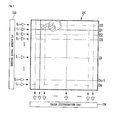
- Fig. 2 is a view for describing a device and a method for sensing touch in accordance with a first embodiment of the present invention.
- the touch sensing device may include a touch sensor panel 210 comprised of a plurality of row wirings and a plurality of column wirings, a sensing signal generator 220 which inputs a sensing signal to the touch sensor panel 210, and a touch determination unit 230 which receives a signal outputted from the column wiring and determines which location of the sensing line the touch has occurred on.
- the row wiring and column wiring of the touch sensing panel 210 correspond to a drive line and a sensing line respectively.
- a touch sensing panel having an orthogonal array consisting of the row and column will be described as an example, the embodiment of the present invention is not limited to this.
- the embodiment of the present invention can be applied to another touch sensing panel having an array of arbitrary dimension, for example, a diagonal array, a concentric array, a 3-dimensional random array, etc., and an array obtained by the application of them.
- the drive line and the sensing line may be formed of a transparent conductive material (e.g., Indium Tin Oxide (ITO), Antimony Tin Oxide (ATO) or the like).
- a transparent conductive material e.g., Indium Tin Oxide (ITO), Antimony Tin Oxide (ATO) or the like.
- the drive line and the sensing line may be also formed of another transparent material or an opaque conductive material including copper and the like.
- the sensing signal generated by the sensing signal generator 220 is inputted to the drive line of the touch sensor panel 210.
- the frequencies of the sensing signals which are inputted to the drive lines D0, D1, D2, ... , Dn respectively may be different from each other. That is, when a frequency of a signal inputted to the first drive line D0 is f0, a frequency of a signal inputted to the second drive line D1 may be f1 and a frequency of a signal inputted to an i th drive line Di may be fi.
- the frequencies may be different from each other.
- the signal outputted through the sensing line is caused to pass through a band pass filter having mutually different pass bands even though the signals are parallelly inputted to the drive lines respectively. Accordingly, it is possible to recognize which location of the drive line the touch has occurred in. For example, when sensing signals having frequencies of f0 and f1 respectively are parallelly inputted to the first and the second drive lines D0 and D1 respectively, a signal outputted from the sensing line has a form of a combination of the signals having the frequencies. Such signals are caused to pass through the band pass filter having a band of f0 and the band pass filter having a band of f1, so that the corresponding signal can be separated.
- the sensing signals can be parallelly inputted, and thus a time required for inputting the signal to one drive line, in other words, an observation time for each drive line is increased compared to a case where the signal is serially inputted. As a result, accuracy of the touch sensing can be increased.
- each signal can be easily separated from a signal obtained by summing all of the signals. For example, when a result obtained by multiplying the sum of a signal having the frequency of f0 and a signal having the frequency of f1 by f0 is integrated with respect to time, only the signal having the frequency of f0 can be extracted.
- the time may be an observation time. For instance, when the signal having the frequency of f0 and the signal having the frequency of f1 have an orthogonal relationship with each other, it is possible to make in a easy way a band pass filter through which only the signal having the frequency of f0 passes.
- a signal having a certain frequency and a signal having an n-times (n is a natural number) frequency of the certain frequency have an orthogonal relationship with each other. Therefore, for example, in case of the touch sensor panel 210 having n number of the drive lines, signals having frequencies of f0, 2f0, 3f0, ... , if0, ... , nf0 respectively may be respectively inputted to the drive lines.
- the touch determination unit 230 receives the signal outputted through each sensing line. Also, the touch determination unit 230 separates the signals in accordance with the frequencies of the signals inputted through the drive lines. As described above, the signal through a combination is multiplied by the frequency of a signal to be separated and then is integrated with respect to time, so that the signals can be separated.
- the signal outputted through a plurality of the sensing lines may be inputted serially or parallelly. When the signal outputted through a plurality of the sensing lines is inputted parallelly, the observation time for one sensing line is increased, so that the touch sensing is efficiently performed.
- the signal outputted through a plurality of the sensing lines is inputted serially, it is enough as long as the received signal is processed serially only by one hardware, so that a simple configuration can be designed.
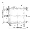
- Fig. 3 is a view for describing a device and a method for sensing touch in accordance with a second embodiment of the present invention.
- the touch sensing device may include a touch sensor panel 310 comprised of a plurality of row wirings and a plurality of column wirings, a sensing signal generator 320 which inputs a sensing signal to the touch sensor panel 310, and a touch determination unit 330 which receives a signal outputted from the column wiring and determines which location of sensing line the touch has occurred on.
- the drive lines of the touch sensor panel 310 may be divided into a plurality of groups. Each group includes two or more drive lines.
- the sensing signals having the same frequency may be inputted to the drive lines belonging to the same group. For example, a sensing signal having the frequency of f0 may be inputted to the drive lines belonging to a first group G0.
- a sensing signal having the frequency of f1 may be inputted to the drive lines belonging to a second group G1.
- the sensing signals having the same frequency are inputted to the drive lines belonging to the same group, the sensing signals must be serially inputted. For instance, when the first drive line D0 and the second drive line D1 belong to the same group, the sensing signal may be inputted to the first drive line D0 during a first time and the sensing signal may be inputted to the second drive line D1 during a second time which is not overlapped with the first time.
- the sensing signals having mutually different frequencies are inputted to the drive lines belonging to mutually different groups, the sensing signals can be parallelly inputted.
- the sensing signal may be inputted to the first drive line D0 and the third drive line D2 during the first time and the sensing signal may be inputted to the second drive line D1 and the fourth drive line D3 during the second time.
- the sensing signals applied to the drive lines which belong to mutually different groups have an orthogonal relationship with each other for the same reason as that of the first embodiment, the signals are not necessarily limited to this.
- the touch determination unit 330 receives the signal outputted through each sensing line. Also, the touch determination unit 330 separates the signals in accordance with the frequencies of the signals inputted through the drive lines. A method for separating the signals is the same as that described above.
- the signal outputted through a plurality of the sensing lines may be inputted serially or parallelly.
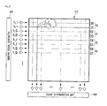
- Fig. 4 is a view for describing a device and a method for sensing touch in accordance with a third embodiment of the present invention.
- the touch sensing device may include a touch sensor panel 410 comprised of a plurality of row wirings and a plurality of column wirings, a sensing signal generator 420 which inputs a sensing signal to the touch sensor panel 410, and a touch determination unit 430 which receives a signal outputted from the column wiring and determines which location of sensing line the touch has occurred on.
- the drive lines of the touch sensor panel 410 may be divided into a plurality of groups.
- the sensing signals having the same frequency and mutually different phases may be inputted to the drive lines belonging to the same group.
- the sensing signal having the frequency of f0 and a first phase delay may be inputted to the first drive line D0
- the sensing signal having the frequency of f0 and a second phase delay may be inputted to the second drive line D1.
- the frequencies of the sensing signals inputted have an orthogonal relationship with each other.
- the signals In order that a plurality of the signals have the same frequency and an orthogonal relationship with each other, the signals must have a phase difference of 90 ⁇ n degrees (n is an integer except 0 and multiples of 4).
- n is an integer except 0 and multiples of 4
- a sensing signal having the frequency of f0 and a phase delay of 0 degree may be inputted to the first drive line D0
- a sensing signal having the frequency of f0 and a phase delay of 90 degree may be inputted to the second drive line D1.
- a sensing signal having the frequency of f0 and a phase delay of 0 degree may be inputted to the first drive line
- a sensing signal having the frequency of f0 and a phase delay of 90 degree may be inputted to the second drive line
- a sensing signal having the frequency of f0 and a phase delay of 180 degree may be inputted to the third drive line
- a sensing signal having the frequency of f0 and a phase delay of 270 degree may be inputted to the fourth drive line.
- the sensing signals have an n-times phase difference of 90 degree even though the sensing signals have the same frequency, it can be said that they have an orthogonal relationship with each other. Therefore, even if the sensing signals having the same frequency and the phase difference are inputted simultaneously to the mutually different drive lines, the signals can be distinguished. Even though a plurality of the signals having the same frequency have a phase difference other than the n-times phase difference of 90 degree, a possibility of the signal separation, as mentioned above, is increased with the extension of the observation time.
- the sensing signal can be parallelly inputted to all of the drive lines. Accordingly, a time required for inputting the sensing signal to each drive line, in other words, an observation time is increased, so that precision of the touch sensing can be improved.
- the touch determination unit 430 receives the signal outputted through each sensing line. Also, the touch determination unit 430 separates the signals in accordance with the frequencies of the signals inputted through the drive lines. A method for separating the signals is the same as that described above.
- the signal outputted through a plurality of the sensing lines may be inputted serially or parallelly. As described above, the parallel input of the signal is advantageous to the improvement of the observation time.
- Fig. 5 is a view for describing a device and a method for sensing touch in accordance with a fourth embodiment of the present invention.
- the touch sensing device may include a touch sensor panel 510 comprised of a plurality of row wirings and a plurality of column wirings, a sensing signal generator 520 which inputs a sensing signal to the touch sensor panel 510, and a touch determination unit 530 which receives a signal outputted from the column wiring and determines which location of sensing line the touch has occurred on.
- the fourth embodiment of the present invention may be performed through a combination of the second embodiment and the third embodiment of the present invention. That is, the drive lines of the touch sensor panel 510 may be divided into a plurality of groups. Sensing signals having the same frequency and mutually different phases may be inputted to at least two among a plurality of the groups. It is enough as long as each group includes at least one drive line. When each group includes two or more drive lines, a sensing signal having the same frequency and the same phase may be inputted to the drive lines belonging to the same group.
- a sensing signal having the frequency of f0 and the first phase delay may be inputted to the first drive line D0 and the second drive line D1
- a sensing signal having the frequency of f0 and the second phase delay different from the first phase delay may be inputted to the third drive line D2 and the fourth drive line D3.
- a sensing signal having the frequency of f1 and the first phase delay may be inputted to the fifth drive line D4 and the sixth drive line D5
- a sensing signal having the frequency of f1 and the second phase delay may be inputted to the seventh drive line D6 and an eighth drive line D7.
- the first phase delay and the second phase delay may be selected, as described above, among 0 degree and 90 ⁇ n degrees. However, the first and the second phase delays are not limited to this.
- the corresponding sensing signal When the sensing signals having the same frequency and the same phase delay are inputted to a plurality of the drive lines, the corresponding sensing signal must be serially inputted.
- the sensing signal In the aforementioned example, the sensing signal must be serially inputted to the first drive line D0 and the second drive line D1. In other words, the sensing signals cannot be inputted to the drive lines belonging to the same group.
- the touch determination unit 530 receives the signal outputted through each sensing line. Also, the touch determination unit 530 separates the signals in accordance with the frequencies of the signals inputted through the drive lines. A method for separating the signals is the same as that described above.
- the signal outputted through a plurality of the sensing lines may be inputted serially or parallelly. As described above, the parallel input of the signal is advantageous to the improvement of the observation time.
- Figs. 6 and 7 are views for describing a method for sensing touch in accordance with a fifth embodiment of the present invention.
- the touch sensing device may include a touch sensor panel 610 comprised of a plurality of row wirings and a plurality of column wirings, a sensing signal generator 620 which inputs a sensing signal to the touch sensor panel 610, and a touch determination unit 630 which receives a signal outputted from the column wiring and determines which location of sensing line the touch has occurred on.
- a sensing signal through a combination of two or more signals having the frequencies and phases, either or both of which are mutually different from each other, is inputted to one drive line.
- a sensing signal through a combination of a plurality of the signals having mutually different frequencies may be inputted to one drive line.
- a sensing signal through a combination of three signals having the frequencies of f00, f01 and f02 respectively may be inputted to the first drive line D0.
- a sensing signal through a combination of three signals having the frequencies of f10, f11 and f12 may be inputted to the second drive line D1.
- noise effect on the touch sensing becomes reduced. For instance, it is assumed that there exists noise having the frequency of f01. In this case, when only a signal having the frequency of f01 is inputted to the first drive line D0, the accuracy of the touch sensing is inevitably reduced by the noise. However, when a sensing signal through a combination of three signals having the frequencies of f00, f01 and f02 respectively is inputted to the first drive line D0, the sensing signals having the frequencies of f00 and f02 are detected except for only the sensing signal having the frequency of f01, so that the touch can be sensed with accuracy.
- the exception of the sensing signal having the frequency of f01 and the detection of the sensing signals having the frequencies of f00 and f02 may be performed by the touch determination unit 630.
- a method for separating only the signal having a specific frequency is the same as that described above.
- a sensing signal through a combination of signals having the same frequency and mutually different phases may be inputted to one drive line.
- a sensing signal through a combination of two signals having the frequency of f00 and mutually different phases may be inputted to the first drive line D0.
- a sensing signal through a combination of signals of f1_I and f1_Q may be inputted to the second drive line D1.
- the combined signals are not limited to this.
- an embodiment can be implemented through a combination of the embodiments shown in Figs. 6 and 7 . That is, a sensing signal through a combination of the signals having mutually different frequencies and mutually different phases may be inputted to one drive line.
- a sensing signal through a combination of three signals of f00_I, f00_Q and f01_I may be inputted to the first drive line D0.
- a sensing signal through a combination of three signals of f10_I, f10_Q and f11_I may be inputted to the second drive line D1.
- a sensing signal through a combination of signals of f00_I, f00_Q, f01_I, f01_Q, ... may be inputted to the first drive line D0.
- a sensing signal through a combination of signals of f10_I, f10_Q, f11_I, f11_Q, ... may be inputted to the second drive line D1.
- a sensing signal through a combination of various signals having mutually different frequencies and mutually different phases may be inputted to one drive line.
- the touch determination unit 630 receives the signal outputted through each sensing line. Also, the touch determination unit 630 separates the signals in accordance with the frequencies of the signals inputted through the drive lines. If there is noise, the accuracy of the touch sensing is improved by excluding a signal having the frequency of the corresponding noise.
Landscapes
- Engineering & Computer Science (AREA)
- General Engineering & Computer Science (AREA)
- Theoretical Computer Science (AREA)
- Human Computer Interaction (AREA)
- Physics & Mathematics (AREA)
- General Physics & Mathematics (AREA)
- Position Input By Displaying (AREA)
Applications Claiming Priority (1)
| Application Number | Priority Date | Filing Date | Title |
|---|---|---|---|
| KR1020120003724A KR101338285B1 (ko) | 2012-01-12 | 2012-01-12 | 터치 패널에서 터치를 감지하기 위한 방법, 장치 및 컴퓨터 판독 가능 기록 매체 |
Publications (2)
| Publication Number | Publication Date |
|---|---|
| EP2615530A2 true EP2615530A2 (de) | 2013-07-17 |
| EP2615530A3 EP2615530A3 (de) | 2016-05-11 |
Family
ID=47594527
Family Applications (1)
| Application Number | Title | Priority Date | Filing Date |
|---|---|---|---|
| EP13150792.3A Withdrawn EP2615530A3 (de) | 2012-01-12 | 2013-01-10 | Verfahren, Verarbeitungsvorrichtung und computerlesbares Aufzeichnungsmedium zum Erfassen einer Berührung auf einem Berührungsbildschirm |
Country Status (3)
| Country | Link |
|---|---|
| EP (1) | EP2615530A3 (de) |
| JP (1) | JP2013143152A (de) |
| KR (1) | KR101338285B1 (de) |
Cited By (4)
| Publication number | Priority date | Publication date | Assignee | Title |
|---|---|---|---|---|
| EP3103000A4 (de) * | 2014-02-04 | 2017-10-25 | Tactual Labs Co. | Frequenzumsetzung bei einem berührungssensor |
| JP2018502382A (ja) * | 2014-12-08 | 2018-01-25 | タクチュアル ラブズ シーオー. | 投影型容量式タッチセンサにおけるクロストークの低減のための差動伝送 |
| CN111475058A (zh) * | 2020-06-23 | 2020-07-31 | 武汉华星光电半导体显示技术有限公司 | 触控显示装置及其触控驱动方法 |
| US11768556B2 (en) | 2020-06-23 | 2023-09-26 | Wuhan China Star Optoelectronics Semiconductor Display Technology Co., Ltd. | Touch display device and touch driving method of same |
Families Citing this family (22)
| Publication number | Priority date | Publication date | Assignee | Title |
|---|---|---|---|---|
| KR101497405B1 (ko) * | 2013-08-07 | 2015-03-04 | 주식회사 하이딥 | 터치패널 입력장치 및 그의 입력검출방법 |
| KR101497404B1 (ko) * | 2013-08-07 | 2015-03-04 | 주식회사 하이딥 | 터치패널 입력장치 및 그의 터치패널 입력검출방법 |
| US11221706B2 (en) | 2013-09-27 | 2022-01-11 | Sensel, Inc. | Tactile touch sensor system and method |
| US10013092B2 (en) | 2013-09-27 | 2018-07-03 | Sensel, Inc. | Tactile touch sensor system and method |
| JP6396478B2 (ja) * | 2013-09-27 | 2018-09-26 | センセル インコーポレイテッドSensel,Inc. | タッチセンサ検出システム及び方法 |
| KR101504031B1 (ko) * | 2013-10-07 | 2015-03-18 | 삼성전기주식회사 | 터치스크린 장치 |
| KR101580176B1 (ko) * | 2013-12-02 | 2015-12-24 | 주식회사 동부하이텍 | 터치 패널을 구동하는 방법 |
| KR102198176B1 (ko) * | 2013-12-13 | 2021-01-04 | 삼성전자주식회사 | 좌표 표시 장치의 주파수 측정 방법 및 그에 따른 전자기기 |
| KR101652028B1 (ko) | 2014-02-19 | 2016-08-30 | 주식회사 하이딥 | 터치 입력 장치 |
| KR102242352B1 (ko) * | 2014-06-23 | 2021-04-20 | 엘지디스플레이 주식회사 | 터치 패널의 구동 장치 및 구동 방법 |
| KR102338709B1 (ko) * | 2015-01-30 | 2021-12-13 | 엘지디스플레이 주식회사 | 표시장치 및 그 구동방법 |
| KR102109419B1 (ko) * | 2015-03-09 | 2020-05-12 | 주식회사 디비하이텍 | 터치 센서 |
| KR102319276B1 (ko) * | 2015-03-09 | 2021-11-01 | 주식회사 디비하이텍 | 터치 센서 |
| US20170371487A1 (en) * | 2016-06-28 | 2017-12-28 | Tactual Labs Co. | Frame-phase synchronization in frequency division modulated touch systems |
| KR102600592B1 (ko) * | 2016-08-29 | 2023-11-10 | 삼성디스플레이 주식회사 | 터치 센서 및 이를 포함하는 표시 장치 |
| CN111465915A (zh) * | 2017-10-13 | 2020-07-28 | 触觉实验室股份有限公司 | 发射器的最小驱动用来增加悬停检测 |
| KR102390164B1 (ko) * | 2017-10-30 | 2022-04-25 | 엘지디스플레이 주식회사 | 터치 센싱 방법, 터치 센싱 회로 및 터치 표시장치 |
| KR102011581B1 (ko) * | 2017-12-26 | 2019-08-16 | 포항공과대학교 산학협력단 | 고주파 대역 전파 기반 터치 감지 장치 및 상기 장치의 구동 방법 |
| EP3740852A4 (de) * | 2018-01-19 | 2021-03-24 | Tactual Labs Co. | Matrixsensor mit empfangsisolierung |
| KR102553515B1 (ko) * | 2018-05-30 | 2023-07-10 | 엘지디스플레이 주식회사 | 터치표시장치, 터치시스템, 터치회로 및 터치센싱방법 |
| JP7117671B2 (ja) * | 2019-03-20 | 2022-08-15 | パナソニックIpマネジメント株式会社 | 表示システムおよび制御方法 |
| JP2025515777A (ja) * | 2022-05-12 | 2025-05-20 | タクチュアル ラブズ シーオー. | 簡略化された製造センサの実装 |
Family Cites Families (15)
| Publication number | Priority date | Publication date | Assignee | Title |
|---|---|---|---|---|
| WO2007017848A2 (en) * | 2005-08-11 | 2007-02-15 | N-Trig Ltd. | Apparatus for object information detection and methods of using same |
| US7812827B2 (en) * | 2007-01-03 | 2010-10-12 | Apple Inc. | Simultaneous sensing arrangement |
| US8493331B2 (en) * | 2007-06-13 | 2013-07-23 | Apple Inc. | Touch detection using multiple simultaneous frequencies |
| US8232977B2 (en) * | 2007-11-14 | 2012-07-31 | N-Trig Ltd. | System and method for detection with a digitizer sensor |
| US10969917B2 (en) * | 2008-01-30 | 2021-04-06 | Apple Inc. | Auto scanning for multiple frequency stimulation multi-touch sensor panels |
| EP2291729B1 (de) * | 2008-04-30 | 2013-06-05 | N-Trig Ltd. | Mehrfachberührungsdetektion |
| JP5216495B2 (ja) * | 2008-09-16 | 2013-06-19 | 株式会社ジャパンディスプレイウェスト | 接触検出装置および表示装置 |
| US8363031B2 (en) * | 2008-09-24 | 2013-01-29 | 3M Innovative Properties Company | Mutual capacitance measuring circuits and methods |
| US8507811B2 (en) * | 2009-02-02 | 2013-08-13 | Apple Inc. | Touch sensor panels with reduced static capacitance |
| US8643624B2 (en) * | 2009-03-18 | 2014-02-04 | Synaptics Incorporated | Capacitive sensing using a segmented common voltage electrode of a display |
| JP5295008B2 (ja) * | 2009-06-18 | 2013-09-18 | 株式会社ワコム | 指示体検出装置 |
| US9753586B2 (en) * | 2009-10-08 | 2017-09-05 | 3M Innovative Properties Company | Multi-touch touch device with multiple drive frequencies and maximum likelihood estimation |
| KR101073309B1 (ko) * | 2009-11-24 | 2011-10-12 | 삼성모바일디스플레이주식회사 | 터치 스크린 시스템 및 그 구동방법 |
| CN101840294B (zh) * | 2010-01-21 | 2012-01-18 | 宸鸿科技(厦门)有限公司 | 一种投射电容式触控面板的扫描方法 |
| JP5496735B2 (ja) * | 2010-03-30 | 2014-05-21 | 株式会社ワコム | 指示体位置検出装置及び指示体位置検出方法 |
-
2012
- 2012-01-12 KR KR1020120003724A patent/KR101338285B1/ko active Active
-
2013
- 2013-01-10 EP EP13150792.3A patent/EP2615530A3/de not_active Withdrawn
- 2013-01-11 JP JP2013003454A patent/JP2013143152A/ja active Pending
Non-Patent Citations (1)
| Title |
|---|
| None |
Cited By (5)
| Publication number | Priority date | Publication date | Assignee | Title |
|---|---|---|---|---|
| EP3103000A4 (de) * | 2014-02-04 | 2017-10-25 | Tactual Labs Co. | Frequenzumsetzung bei einem berührungssensor |
| JP2018502382A (ja) * | 2014-12-08 | 2018-01-25 | タクチュアル ラブズ シーオー. | 投影型容量式タッチセンサにおけるクロストークの低減のための差動伝送 |
| CN111475058A (zh) * | 2020-06-23 | 2020-07-31 | 武汉华星光电半导体显示技术有限公司 | 触控显示装置及其触控驱动方法 |
| WO2021258527A1 (zh) * | 2020-06-23 | 2021-12-30 | 武汉华星光电半导体显示技术有限公司 | 触控显示装置及其触控驱动方法 |
| US11768556B2 (en) | 2020-06-23 | 2023-09-26 | Wuhan China Star Optoelectronics Semiconductor Display Technology Co., Ltd. | Touch display device and touch driving method of same |
Also Published As
| Publication number | Publication date |
|---|---|
| JP2013143152A (ja) | 2013-07-22 |
| KR101338285B1 (ko) | 2013-12-09 |
| KR20130083152A (ko) | 2013-07-22 |
| EP2615530A3 (de) | 2016-05-11 |
Similar Documents
| Publication | Publication Date | Title |
|---|---|---|
| EP2615530A2 (de) | Verfahren, Verarbeitungsvorrichtung und computerlesbares Aufzeichnungsmedium zum Erfassen einer Berührung auf einem Berührungsbildschirm | |
| US20140198053A1 (en) | Method, device and computer-readable recording medium for sensing touch on touch panel | |
| US9223437B2 (en) | Method, touch sensing apparatus and computer-readable recording medium for minimizing noise on touch panel | |
| US9965100B2 (en) | Scan sequence generator | |
| JP5301696B2 (ja) | 多重同時周波数検出 | |
| US10261628B2 (en) | Driving chip, circuit film, chip-on-film type driving circuit, and display device having built-in touchscreen | |
| US20110248932A1 (en) | Ghost cancellation method for multi-touch sensitive device | |
| US9927928B2 (en) | Touch panel input device and input detection method thereof | |
| US8743085B2 (en) | Touch input device for switching driving signals | |
| US9354746B2 (en) | Capacitive touch panel | |
| KR20150077186A (ko) | 터치스크린 장치 및 터치 감지 방법 | |
| KR102697626B1 (ko) | 정전식 센서의 커패시턴스 획득 방법 및 정전식 센서 | |
| US20170185219A1 (en) | Touch screen display device | |
| US9134862B2 (en) | Parallelogram electrode touch panel | |
| CN115373538A (zh) | 触控控制器、触控感测装置以及触控感测模块 | |
| KR20150120713A (ko) | 터치 감지 장치 및 이를 포함하는 터치스크린 장치 | |
| CN104793823A (zh) | 互电容式触控显示面板及其触控检测方法 | |
| CN108700974A (zh) | 电容检测电路及电子装置 | |
| CN102012766A (zh) | 触摸屏上侦测多指触控的方法 |
Legal Events
| Date | Code | Title | Description |
|---|---|---|---|
| PUAI | Public reference made under article 153(3) epc to a published international application that has entered the european phase |
Free format text: ORIGINAL CODE: 0009012 |
|
| 17P | Request for examination filed |
Effective date: 20130208 |
|
| AK | Designated contracting states |
Kind code of ref document: A2 Designated state(s): AL AT BE BG CH CY CZ DE DK EE ES FI FR GB GR HR HU IE IS IT LI LT LU LV MC MK MT NL NO PL PT RO RS SE SI SK SM TR |
|
| AX | Request for extension of the european patent |
Extension state: BA ME |
|
| RIN1 | Information on inventor provided before grant (corrected) |
Inventor name: BONKEE, KIM Inventor name: SANGSIC, YOON |
|
| PUAL | Search report despatched |
Free format text: ORIGINAL CODE: 0009013 |
|
| AK | Designated contracting states |
Kind code of ref document: A3 Designated state(s): AL AT BE BG CH CY CZ DE DK EE ES FI FR GB GR HR HU IE IS IT LI LT LU LV MC MK MT NL NO PL PT RO RS SE SI SK SM TR |
|
| AX | Request for extension of the european patent |
Extension state: BA ME |
|
| RIC1 | Information provided on ipc code assigned before grant |
Ipc: G06F 3/041 20060101AFI20160401BHEP Ipc: G06F 3/044 20060101ALN20160401BHEP |
|
| STAA | Information on the status of an ep patent application or granted ep patent |
Free format text: STATUS: THE APPLICATION IS DEEMED TO BE WITHDRAWN |
|
| 18D | Application deemed to be withdrawn |
Effective date: 20161112 |