EP2615730B1 - Ensemble démarreur-générateur sans balais et procédé de commande d'excitation de flux magnétique - Google Patents
Ensemble démarreur-générateur sans balais et procédé de commande d'excitation de flux magnétique Download PDFInfo
- Publication number
- EP2615730B1 EP2615730B1 EP13151222.0A EP13151222A EP2615730B1 EP 2615730 B1 EP2615730 B1 EP 2615730B1 EP 13151222 A EP13151222 A EP 13151222A EP 2615730 B1 EP2615730 B1 EP 2615730B1
- Authority
- EP
- European Patent Office
- Prior art keywords
- magnetic
- generator assembly
- stator
- brushless starter
- rotor
- Prior art date
- Legal status (The legal status is an assumption and is not a legal conclusion. Google has not performed a legal analysis and makes no representation as to the accuracy of the status listed.)
- Active
Links
- 230000005284 excitation Effects 0.000 title claims description 7
- 238000000034 method Methods 0.000 title claims description 4
- 230000004907 flux Effects 0.000 title description 14
- 230000005672 electromagnetic field Effects 0.000 claims description 17
- 239000006148 magnetic separator Substances 0.000 claims description 14
- 230000035699 permeability Effects 0.000 claims description 8
- 238000001514 detection method Methods 0.000 claims description 7
- 230000007423 decrease Effects 0.000 claims description 6
- 238000005728 strengthening Methods 0.000 claims 1
- 238000004804 winding Methods 0.000 description 17
- 230000003247 decreasing effect Effects 0.000 description 5
- 230000001105 regulatory effect Effects 0.000 description 5
- 230000001276 controlling effect Effects 0.000 description 4
- 238000010248 power generation Methods 0.000 description 4
- 230000033228 biological regulation Effects 0.000 description 1
- 238000010586 diagram Methods 0.000 description 1
- 239000000463 material Substances 0.000 description 1
- 238000012986 modification Methods 0.000 description 1
- 230000004048 modification Effects 0.000 description 1
- 239000007858 starting material Substances 0.000 description 1
- 230000001360 synchronised effect Effects 0.000 description 1
Images





Classifications
-
- H—ELECTRICITY
- H02—GENERATION; CONVERSION OR DISTRIBUTION OF ELECTRIC POWER
- H02K—DYNAMO-ELECTRIC MACHINES
- H02K21/00—Synchronous motors having permanent magnets; Synchronous generators having permanent magnets
- H02K21/02—Details
- H02K21/04—Windings on magnets for additional excitation ; Windings and magnets for additional excitation
- H02K21/046—Windings on magnets for additional excitation ; Windings and magnets for additional excitation with rotating permanent magnets and stationary field winding
-
- H—ELECTRICITY
- H02—GENERATION; CONVERSION OR DISTRIBUTION OF ELECTRIC POWER
- H02K—DYNAMO-ELECTRIC MACHINES
- H02K1/00—Details of the magnetic circuit
- H02K1/06—Details of the magnetic circuit characterised by the shape, form or construction
- H02K1/12—Stationary parts of the magnetic circuit
- H02K1/18—Means for mounting or fastening magnetic stationary parts on to, or to, the stator structures
- H02K1/185—Means for mounting or fastening magnetic stationary parts on to, or to, the stator structures to outer stators
-
- H—ELECTRICITY
- H02—GENERATION; CONVERSION OR DISTRIBUTION OF ELECTRIC POWER
- H02K—DYNAMO-ELECTRIC MACHINES
- H02K11/00—Structural association of dynamo-electric machines with electric components or with devices for shielding, monitoring or protection
- H02K11/20—Structural association of dynamo-electric machines with electric components or with devices for shielding, monitoring or protection for measuring, monitoring, testing, protecting or switching
- H02K11/26—Devices for sensing voltage, or actuated thereby, e.g. overvoltage protection devices
Definitions
- the present invention pertains to the art of power generation devices, and in particular, to brushless starter generators. Electrical machines of this type are disclosed in US 5942829 , DE 4115887 and US 3396325 .
- Certain power generation applications such as aerospace power generation applications, require that highly regulated electrical power be delivered from a power generation system having a rotor that rotates over a wide range of speeds to a wide range of loads.
- Wound field synchronous generators may be used to generate power and receive rotational power from either a high-pressure or high-speed spool of a gas turbine engine.
- a reduction gearbox is required between the spool of the gas turbine engine and the generator.
- Permanent magnet starter-generators may also be used to generate power, and can be directly connected to high-pressure or high-speed engine spools.
- conventional high-pressure connected and high-speed connected permanent magnet starter-generators are unable to effectively regulate the induced electromagnetic fields (EMF) and output voltages of the starter-generator.
- EMF induced electromagnetic fields
- FIG. 1 illustrates a brushless starter-generator assembly 1 (also referred to as "assembly 1") according to an example useful for understanding the invention.
- the assembly 1 includes a stator assembly 10 surrounding a rotor 20.
- the stator assembly 10 is a stationary assembly, and the rotor 20 rotates with respect to the stator assembly 10.
- At least one field coil 32 is located radially outward from the rotor 20.
- a field coil 32 is located radially outward from the rotor 20 with respect to an axis A.
- the rotor 20 includes a shaft 22, protrusions 24, and permanent magnets 28 positioned between the protrusions 24.
- the protrusions 24 are also referred to in the present specification and claims as rotor poles, laminated poles, laminated rotor poles, and poles 24.
- the permanent magnets are also referred to in the specification and claims as magnets 28.
- the poles 24 and permanent magnets 28 are fixed with respect to the shaft 22 and rotate about the shaft 22 as it rotates about the axis A.
- the rotor 20 also includes a magnetic hub 26 surrounding the shaft 22 in a radial direction with respect to the axis A and located between the shaft 22 and the magnets 28.
- the stator assembly 10 includes a stator stack 12 and one or more windings 14 wound in the stator stack 12.
- the windings 14 comprise conductive wire wound to generate and/or receive an electromagnetic field (EMF). Only some windings 14 of the stator 10 are illustrated in FIG. 1 for purposes of ease of description. However, any number of windings 14 may be implemented according to the desired specifications of the brushless starter-generator assembly 1.
- the stator assembly 10 further includes a magnetic sleeve 18 around an outer circumference of the stator stack 12, and a non-magnetic separator 16 between the magnetic sleeve 18 and the stator stack 12.
- the brushless starter-generator assembly 1 may regulate an induced electromagnetic field (EMF) in the windings 14 by regulating a flux produced by the permanent magnets 28 of the rotor 20.
- EMF induced electromagnetic field
- the brushless starter-generator assembly 1 of the example of FIG. 1 may result in an increase in voltage regulation by a factor of 10 or more, with only a marginal increase in a weight of the brushless starter-generator assembly 1.
- the field coil 32 generates a magnetic field to vary the magnetic saturation, and the magnetic reluctance, of the magnetic hub 26. By varying the magnetic flux output from the field coil 32, the magnetic reluctance of the magnetic hub 26 may be adjusted. Referring to FIG. 6 , when no magnetic field is generated in the field coil 32, the magnetic hub 26 maintains a low magnetic saturation, a low magnetic reluctance, and a high magnetic permeability, and the magnetic flux generated by the permanent magnets 28 is substantially maintained within the rotor 10.
- the magnetic permeability of the magnetic hub 26 decreases. Because the magnetic permeability of the magnetic hub 26 is decreased, the laminated rotor poles 24 have a relatively higher magnetic permeability, and the magnetic flux generated by the permanent magnets 28 flows through the more permeable regions of the laminated rotor poles 24 to cross the air gap 29 to the windings 14 of the stator 10. As a result, the percentage of permanent magnet flux linking the stator windings 14 increases, and the current generated in the windings 14 increases.
- the magnetic hub 26 on the rotor 20 and field coil 32 located radially outward from the magnetic hub 26 provide a means to control the EMF of the permanent magnets 28 of the rotor 20, an EMF induced in the windings 14, and a voltage output from the brushless starter-generator assembly 1 via the windings 14.
- the magnetic flux produced by the field coils 32a and 32b is forced to flow axially through the magnetic hub 26 and return through the magnetic sleeve 18 by positioning the non-magnetic separator 16 between the magnetic sleeve 18 and the stator stack 12.
- the non-magnetic separator 16 prevents the magnetic flux produced by the field coils 32a and 32b from flowing from the magnetic hub 26 through the laminated rotor poles 24 and through the stator stack 12.
- FIG. 2 illustrates a cross-section of the stator assembly 10 and rotor 20 according to an example useful for understanding the invention.
- the stator assembly 10 includes a stator stack 12, windings 14, a magnetic sleeve 18 surrounding an outer circumference of the stator stack 12, and a non-magnetic separator 16 located between the stator stack 12 and the magnetic sleeve 18.
- the rotor 20 includes a shaft 22, rotor poles 24 extending radially from the shaft 22, and permanent magnets 28 located between, or embedded in, the rotor poles 24.
- a magnetic hub 26 surrounds the shaft 22 and is located between the shaft 22 and the rotor poles 24.
- FIG. 3 illustrates a cross-section view of the brushless starter-generator assembly 1 of FIG. 2 , taken along the line B-B'.
- the brushless starter-generator assembly 1 may include a main housing 40 surrounding the stator assembly 10 and the rotor 20.
- the stator assembly 10 may be fixed with respect to the main housing 40, and bearings 42 may be positioned between the main housing 40 and the shaft 22 to support the shaft 22 and to allow the shaft 22 to rotate with respect to the main housing 40.
- the magnetic hub 26 may be located between the shaft 22 and the bearings 42 to support the magnetic hub 26 and to allow the magnetic hub 26 to rotate with respect to the main housing 40.
- the main housing 40 has a cylindrical shape having openings at the ends of the cylinder to allow the magnetic hub 26 and shaft 22 to pass therethrough, and the bearings 42 may be located at the openings.
- the stator assembly 10 may include a magnetic sleeve 18 having radial portions 18a extending radially from the magnetic hub 26, and a length portion 18b extending lengthwise along an outer radial end of the stator stack 12, parallel to the axis A. Ends of the radial portions 18a may be spaced apart from the magnetic hub 26.
- the magnetic sleeve 18 has a cylindrical shape
- the radial portions 18a comprise circular ends of the cylinder having openings to allow the magnetic hub 26 and shaft 22 to pass therethrough
- the length portion 18b comprises the cylindrical sides of the cylinder.
- the ends of the radial portions 18a extend toward the magnetic hub 26, past an outer circumference of the rotor poles 24 in a radial direction with respect to the axis A.
- a non-magnetic separator 16 may be positioned between the length portion 18b of the magnetic sleeve 18 and the stator stack 12.
- the non-magnetic separator 16 has a substantially cylindrical shape.
- the field coil 32 includes first and second field coils 32a and 32b located radially outward from the rotor 20 on either side of the stator stack 12 in a direction of the axis A, or in other words, in a longitudinal direction.
- the field excitation coils 32a and 32b may be connected in series so that an appropriate combination of a high number of turns and a low current may create the magnetomotive force to produce a level of axial magnetic flux that flows through the rotor hub and returns through the magnetic sleeve 18 around the stator assembly 10.
- the field coils 32a and 32b are positioned between the stator stack 12 and the radial portions 18a of the magnetic sleeve 18.
- the field coils 32a and 32b may have O shapes centered around a point on the axis A.
- An outer circumference of the field coils 32a and 32b may contact an inner circumference of the length portion 18b of the magnetic hub 18.
- the field coils 32a and 32b surround at least portions of the stator assembly 10.
- the field coils 32a and 32b are located to cover or surround longitudinal side surfaces of the stator stack 12 and the non-magnetic separator 16.
- the term “surrounding” includes covering an element in a longitudinal direction.
- the term “surrounding” may include in addition or in the alternative, covering an element in a radial direction.
- the term surrounding at least a portion includes covering a portion of an element, and may include covering only a part of an element or covering the entire element.
- the field coils 32a and 32b are located radially outward from the rotor poles 24 and permanent magnets 28, and are offset from the rotor poles 24 in the longitudinal direction toward the ends of the brushless starter-generator assembly 1.
- the field coil 32 may be located directly radially outward from the permanent magnets 28. In other words, the field coils 32 may not be axially offset from the permanent magnets.
- FIG. 4 illustrates an embodiment of the present invention including field coils 32a and 32b that are located directly radially outward from the rotor poles 24 and the permanent magnets 28.
- field coils 32a and 32b are located within the stator stack 24. Grooves are formed in the stator stack 12, and the field coils 32a and 32b are formed in the grooves.
- the field coils 32a and 32b may have outer circumferences contacting an inner circumference of the non-magnetic separator 16.
- the magnetic sleeve 18 may not include radial portions 18a, and may instead include only a length portion 18b.
- the field coils 32a and 32b may be located closer to opposite ends of the stator stack 12 in a direction of the axis A, or in other words in a longitudinal direction, than to a center of the stator stack 12 in the longitudinal direction.
- the field coils 32a and 32b are adjacent to ends of the non-magnetic separator 16 in the longitudinal direction.
- a number of field coils 32 may be greater than two.
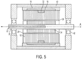
- FIG. 5 illustrates an an example useful for understanding the invention in which only one field coil 32 is located in the brushless starter-generator assembly 1.
- the field coil 32 is located within the stator stack 12 at a center point of the stator stack 12 in the direction of the axis A, or in other words, at a longitudinal center of the stator stack 12.
- the field coil 32 may have an outer circumference contacting an inner circumference of the non-magnetic separator 16.
- the magnetic sleeve 18 does not include radial portions 18a. Instead, the magnetic sleeve 18 may include only a length portion 18b.
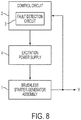
- FIG. 8 illustrates a system for controlling the voltage output from a brushless starter-generator assembly 1 by controlling the EMF induced in windings 14 according to embodiments of the present invention.
- the system of FIG. 8 will be described with reference to the elements of the brushless starter-generator assembly 1 of the embodiment of FIG. 1 .
- the system includes the brushless starter-generator assembly 1 to generate an output voltage V based upon the rotation of the rotor 20.
- a control circuit 2 controls an excitation power supply 4, which provides power to the field coil 32.
- the magnetic saturation of the magnetic hub 26 increases, and the magnetic permeability of the magnetic hub 26 decreases. Consequently, the magnetic flux produced by the permanent magnets 28 flows through the rotor poles 24 to the windings 14 of the stator 10, and the voltage output from the brushless starter-generator assembly 1 increases.
- the control circuit 2 may include a detection circuit, such as a fault detection circuit 3, that monitors the brushless starter-generator assembly 1 to detect whether a characteristic of the brushless starter-generator assembly exceeds a predetermined threshold.
- a fault detection circuit 3 may monitor an output voltage of the brushless starter-generator assembly 1 to determine whether the output voltage level V exceeds a fault level of voltage. In such a case, the control circuit 2 may shut down or decrease the power output from the excitation power supply 4 to the field coil 32 to reduce the voltage output from the brushless starter-generator assembly 1.
- control circuit 2 may monitor any characteristic, such as an output EMF, current, temperature, vibration, or any other desired characteristic.
- the control circuit 2 may include at least a processor including a comparator to compare a detected characteristic to a threshold, memory to store the threshold and a program to generate output signals to control power supplied to or generated from the brushless starter-generator assembly 1, an I/O ports connected to the brushless starter-generator assembly 1, and to any other device to interact with the control circuit 2.
- a processor including a comparator to compare a detected characteristic to a threshold, memory to store the threshold and a program to generate output signals to control power supplied to or generated from the brushless starter-generator assembly 1, an I/O ports connected to the brushless starter-generator assembly 1, and to any other device to interact with the control circuit 2.
- FIG. 9 illustrates a method of controlling the brushless starter-generator assembly 1 according to an embodiment of the invention.
- the rotor 20 is rotated with respect to the stator assembly 10.
- the rotor 20 may be connected to a turbine or other driving system to drive the shaft 22 to rotate the rotor 20.
- a characteristic output from the brushless starter-generator assembly 1 is detected.
- the characteristic may be an output voltage or current, an EMF, vibration, temperature, or any other characteristic that provides information about the operation of the brushless starter-generator assembly 1.
- a control circuit 2 may detect a low output voltage V, and may increase a current to the field coil 32 to increase the magnetic reluctance of the magnetic hub 26, and increase the EMF induced in the windings 14 of the stator 10. The voltage V may then increase to a desired operating voltage, and the control circuit 2 may monitor the voltage V and adjust the current to the field coil 32 to maintain a desired operating voltage.
- a fault detection circuit 3 detects a fault-level voltage, such as a short-circuit voltage
- the control circuit 2 may shut off current to the field coil 32, increasing the magnetic permeability of the magnetic hub 26, and decreasing the EMF induced in the windings 14 to decrease or stop the voltage output from the brushless starter-generator assembly 1.
- the EMF induced in the windings of a brushless starter-generator assembly may be effectively controlled by regulating the permanent magnet flux produced in the rotor of the brushless starter-generator assembly, rather than in the stator. Regulating the magnetic flux of the permanent magnets of the rotor allows the brushless starter-generator assembly to operate at higher speeds, potentially generating a greater voltage relative to devices that regulate voltage or other characteristics of the stator.
- the above-described embodiments provide for a system and apparatus to shut off power from a brushless starter-generator assembly due to feeder cable short-circuits or other system faults, since shutting off power to the field coils reduces the voltage output from the brushless starter-generator assembly.
Landscapes
- Engineering & Computer Science (AREA)
- Power Engineering (AREA)
- Permanent Magnet Type Synchronous Machine (AREA)
Claims (10)
- Ensemble démarreur-générateur sans balais (1), comprenant :un ensemble stator (10) comprenant un empilement statorique (12), un manchon magnétique (18) situé autour d'une circonférence extérieure de l'empilement statorique (12), et un séparateur non magnétique (16) situé entre l'empilement statorique (12) et le manchon magnétique (18) ;un rotor (20) comportant un moyeu magnétique (26) et des pôles de rotor (24) et disposé au moins partiellement à l'intérieur de l'ensemble stator (10), le rotor (20) étant conçu pour tourner autour d'un axe (A) ; etune bobine de champ (32) entourant une partie de l'ensemble stator (10) et située radialement vers l'extérieur du rotor (20) par rapport à l'axe (A), la bobine de champ (32) comportant des première et seconde bobines de champ (32a, 32b), chacune étant disposée autour d'un point sur l'axe (A) et à l'intérieur d'une largeur axiale de l'empilement statorique (12) dans une direction de l'axe (A),les première et seconde bobines de champ (32a, 32b) étant formées dans des première et seconde rainures respectives dans l'empilement statorique (12), les première et seconde rainures étant situées à des extrémités axiales opposées de l'empilement statorique (12),dans lequel les bobines de champ (32a, 32b) sont :situées directement radialement vers l'extérieur des pôles de rotor (24) ; espacées les une des autres dans la direction de l'axe (A) ; et adjacentes aux extrémités du séparateur non magnétique (16) dans une direction longitudinale, dans lequel une circonférence extérieure des bobines de champ (32a, 32b) est en contact avec une circonférence intérieure du séparateur non magnétique (16) ; etdans lequel le moyeu magnétique (26) a une perméabilité magnétique qui diminue sur la base d'un renforcement d'un champ magnétique généré par la bobine de champ (32).
- Ensemble démarreur-générateur sans balais selon la revendication 1, dans lequel les première et seconde bobines de champ (32a, 32b) entourent deux régions de l'empilement statorique (12) dans une direction de l'axe (A).
- Ensemble démarreur-générateur sans balais selon la revendication 1, dans lequel les circonférences extérieures des première et seconde bobines de champ (32a, 32b) sont en contact avec une circonférence intérieure du séparateur non magnétique (16) .
- Ensemble démarreur-générateur sans balais selon une quelconque revendication précédente, dans lequel le rotor (20) comprend :un arbre (22) qui tourne autour de l'axe (A) ;des pôles de rotor (24) fixés par rapport à l'arbre (22) ; etdes aimants permanents (28) fixés par rapport aux pôles de rotor (24),dans lequel le moyeu magnétique (26) est situé entre les aimants permanents (28) et l'arbre (22).
- Ensemble démarreur-générateur sans balais selon une quelconque revendication précédente, dans lequel la bobine de champ (32) est conçue pour augmenter une saturation magnétique du moyeu magnétique (26) lorsqu'un courant est appliqué à la bobine de champ (32).
- Ensemble démarreur-générateur sans balais selon une quelconque revendication précédente, dans lequel chacune des première et seconde bobines de champ (32a, 32b) est une bobine en forme de O centrée autour de l'axe (A) et entourant l'axe (A) .
- Ensemble démarreur-générateur sans balais selon une quelconque revendication précédente, comprenant en outre :un boîtier (40) fixé par rapport au stator (10) ; etdes paliers (42) pour supporter le moyeu magnétique (26) par rapport au boîtier (40) ; de préférencedans lequel le boîtier (40) et l'empilement statorique (12) ont une forme sensiblement cylindrique.
- Ensemble démarreur-générateur sans balais selon une quelconque revendication précédente comprenant :un circuit de commande (2) pour commander un courant fourni à la bobine de champ (32),dans lequel le circuit de commande (2) comporte un circuit de détection pour détecter une caractéristique de l'ensemble démarreur-générateur sans balais (1), etle circuit de commande (2) est conçu pour ajuster le courant à l'ensemble démarreur-générateur sans balais (1) lorsque la caractéristique détectée dépasse un seuil prédéterminé ; de préférencedans lequel le circuit de détection est un circuit de détection de défauts (3), etle seuil prédéterminé est une tension correspondant à un court-circuit.
- Système selon la revendication 8, comprenant en outre une source d'énergie d'excitation (4) raccordée à la bobine de champ (32),
dans lequel le circuit de commande (2) commande le courant fourni à la bobine de champ (32) en commandant la sortie de la source d'énergie d'excitation (4). - Procédé de commande de l'ensemble démarreur-générateur sans balais selon une quelconque revendication précédente, comprenant :la rotation (52) du rotor (20) autour de l'axe (A) par rapport à l'ensemble stator (10) pour générer un champ électromagnétique,le rotor (20) comportant un arbre (22), des aimants permanents (28) tournant autour de l'arbre (22), et un moyeu magnétique (26) situé entre l'arbre (22) et les aimants permanents (28) ; etl'ajustement (56) de l'énergie fournie à la bobine de champ (32) entournant une ou plusieurs parties de l'ensemble stator (10) pour ajuster une réluctance magnétique du moyeu magnétique (26).
Applications Claiming Priority (1)
| Application Number | Priority Date | Filing Date | Title |
|---|---|---|---|
| US13/350,084 US8922154B2 (en) | 2012-01-13 | 2012-01-13 | Brushless starter-generator assembly and method to control magnetic flux excitation |
Publications (3)
| Publication Number | Publication Date |
|---|---|
| EP2615730A2 EP2615730A2 (fr) | 2013-07-17 |
| EP2615730A3 EP2615730A3 (fr) | 2017-08-09 |
| EP2615730B1 true EP2615730B1 (fr) | 2019-07-24 |
Family
ID=47561388
Family Applications (1)
| Application Number | Title | Priority Date | Filing Date |
|---|---|---|---|
| EP13151222.0A Active EP2615730B1 (fr) | 2012-01-13 | 2013-01-14 | Ensemble démarreur-générateur sans balais et procédé de commande d'excitation de flux magnétique |
Country Status (2)
| Country | Link |
|---|---|
| US (1) | US8922154B2 (fr) |
| EP (1) | EP2615730B1 (fr) |
Families Citing this family (5)
| Publication number | Priority date | Publication date | Assignee | Title |
|---|---|---|---|---|
| WO2018225876A1 (fr) * | 2017-06-06 | 2018-12-13 | Kamanga Geoffrey Kamau | Générateur d'énergie électrique excité par un amplificateur de flux magnétique |
| US10246117B1 (en) * | 2018-08-09 | 2019-04-02 | Li-Sheng Chien | Hand-driven, wheeled carrier deceleration device and hand-driven, wheeled carrier having the same |
| US20230378842A1 (en) * | 2020-09-21 | 2023-11-23 | Lg Innotek Co., Ltd. | Motor |
| CN117411363B (zh) * | 2023-10-08 | 2025-09-30 | 龙岩市海德馨汽车有限公司 | 一种双电压的电源车 |
| CN121012253B (zh) * | 2025-10-27 | 2026-02-24 | 云梦山(常州)科技有限公司 | 一种具有防潮功能的航空用起动电机 |
Family Cites Families (25)
| Publication number | Priority date | Publication date | Assignee | Title |
|---|---|---|---|---|
| DE1121716B (de) * | 1960-07-14 | 1962-01-11 | Siemens Ag | Wechselstrom- bzw. Drehstromgenerator mit Klauenpollaeufer |
| GB1071113A (en) * | 1963-07-05 | 1967-06-07 | Siemens Ag | Improvements in or relating to electrical machines |
| US3396325A (en) * | 1965-07-21 | 1968-08-06 | Ralph E. Hopkins | Voltage control of permanent magnet generators |
| DE4115887A1 (de) * | 1990-05-28 | 1991-12-05 | Siemens Ag | Elektrische maschine mit einem staender und einem permanentmagnetbestueckten laeufer |
| US5504382A (en) * | 1994-01-24 | 1996-04-02 | Douglass; Michael J. | Field controlled permanent magnet alternator |
| US5942829A (en) * | 1997-08-13 | 1999-08-24 | Alliedsignal Inc. | Hybrid electrical machine including homopolar rotor and stator therefor |
| US6455975B1 (en) | 1999-12-03 | 2002-09-24 | Pacific Scientific Electro Kinetics Division | Regulated permanent magnet generator |
| US6992403B1 (en) * | 2001-03-08 | 2006-01-31 | Pacific Scientific | Electric power and start system |
| US6844707B1 (en) * | 2003-12-30 | 2005-01-18 | Pacific Scientific/Electro Kinetics Division | AC/DC brushless starter-generator |
| US7064526B2 (en) | 2004-04-23 | 2006-06-20 | Astronics Advanced Electronic Systems Corp. | Fault tolerant architecture for permanent magnet starter generator subsystem |
| US7982350B2 (en) * | 2004-10-25 | 2011-07-19 | Novatorque, Inc. | Conical magnets and rotor-stator structures for electrodynamic machines |
| US7061152B2 (en) * | 2004-10-25 | 2006-06-13 | Novatorque, Inc. | Rotor-stator structure for electrodynamic machines |
| EP1847010A1 (fr) * | 2005-02-02 | 2007-10-24 | Magnetic Applications Inc. | Generateur d'impulsions pour un redresseur controle |
| US7385332B2 (en) | 2006-04-17 | 2008-06-10 | Hamilton Sundstrand Corporation | Permanent magnet dynamoelectric machine with axially displaceable permanent magnet rotor assembly |
| US7557482B2 (en) * | 2006-07-31 | 2009-07-07 | Caterpillar Inc. | Axial-flux electric machine |
| US7439713B2 (en) | 2006-09-20 | 2008-10-21 | Pratt & Whitney Canada Corp. | Modulation control of power generation system |
| US7834509B2 (en) * | 2008-02-28 | 2010-11-16 | Hamilton Sundstrand Corporation | Rotor assembly for electromechanical machine |
| US7859231B2 (en) | 2008-04-02 | 2010-12-28 | Hamilton Sundstrand Corporation | Permanent magnet electric generator with variable magnet flux excitation |
| US8450888B2 (en) * | 2009-04-20 | 2013-05-28 | General Electric Company | Integrated brushless starter/generator system |
| JP5442388B2 (ja) * | 2009-10-22 | 2014-03-12 | 株式会社日立産機システム | 磁性鉄心およびその製造方法、アキシャルギャップ型回転電機、静止機 |
| US8754560B2 (en) * | 2009-11-25 | 2014-06-17 | Uqm Technologies, Inc. | Rotor for a permanent magnet electric machine |
| US8760030B2 (en) * | 2010-06-07 | 2014-06-24 | David A. Ross | Flexible rotor sequentially actuated motor/generator |
| GB2481406B (en) * | 2010-06-22 | 2016-01-20 | Ametek Airtechnology Group Ltd | A resolver |
| DE202010015364U1 (de) * | 2010-11-11 | 2012-02-17 | Hans-Peter Wyremba | Bürstenloser Elektromotor oder Generator in Schalenbauweise |
| JP5591099B2 (ja) * | 2010-12-28 | 2014-09-17 | 三菱電機株式会社 | 圧縮機および冷凍サイクル装置 |
-
2012
- 2012-01-13 US US13/350,084 patent/US8922154B2/en active Active
-
2013
- 2013-01-14 EP EP13151222.0A patent/EP2615730B1/fr active Active
Non-Patent Citations (1)
| Title |
|---|
| None * |
Also Published As
| Publication number | Publication date |
|---|---|
| US8922154B2 (en) | 2014-12-30 |
| EP2615730A2 (fr) | 2013-07-17 |
| US20130181653A1 (en) | 2013-07-18 |
| EP2615730A3 (fr) | 2017-08-09 |
Similar Documents
| Publication | Publication Date | Title |
|---|---|---|
| EP2782226B1 (fr) | Rotor de machine électrique à aimants permanents avec flux magnétique contrôlé | |
| US7973444B2 (en) | Electric machine and rotor for the same | |
| JP6723490B1 (ja) | 回転電機の回転子 | |
| EP2615730B1 (fr) | Ensemble démarreur-générateur sans balais et procédé de commande d'excitation de flux magnétique | |
| JP2007300787A (ja) | 発電機・電動機用回転子 | |
| US20180254688A1 (en) | Wound-rotor synchronous machine with permanent magnets | |
| US9590457B2 (en) | Stator of a rotary electric machine | |
| US20140368075A1 (en) | Permanent magnet synchronous machines with magnetic flux regulation | |
| CN102664502A (zh) | 混合永磁与电磁复合励磁发电机 | |
| EP3163726A1 (fr) | Commande de flux d'une machine électrique à aimant permanent | |
| JP5120801B2 (ja) | 回転機及び回転機を製造する方法 | |
| KR20130051398A (ko) | 전자기 장치 | |
| US10110079B2 (en) | Wound field generator system featuring combined permanent magnet generator excitation with exciter stator | |
| US6388356B1 (en) | Methods and apparatus for controlling electromagnetic flux in dynamoelectric machines | |
| RU2470446C1 (ru) | Стабилизированный аксиальный генератор постоянного тока | |
| WO2019098341A1 (fr) | Alternateur synchrone sans balai | |
| EP1679427B1 (fr) | Turbo-générateur | |
| GB2408154A (en) | Stator/rotor arrangement and exciter for an axial flux AC machine | |
| JP2017520232A (ja) | 同期機への励磁電流の供給 | |
| US20170133916A1 (en) | Generator | |
| US20160380501A1 (en) | End winding support for an electric generator | |
| CN105958777A (zh) | 爪极式电磁与永磁混联式发电机 | |
| JP2016067127A (ja) | 発電機 | |
| JP2010110036A (ja) | ブラシ給電式ハイブリッド励磁モータ及びブラシ給電式ハイブリッド励磁モータの駆動方法 | |
| CN105811707A (zh) | 无刷电磁与永磁混联式发电装置 |
Legal Events
| Date | Code | Title | Description |
|---|---|---|---|
| PUAI | Public reference made under article 153(3) epc to a published international application that has entered the european phase |
Free format text: ORIGINAL CODE: 0009012 |
|
| AK | Designated contracting states |
Kind code of ref document: A2 Designated state(s): AL AT BE BG CH CY CZ DE DK EE ES FI FR GB GR HR HU IE IS IT LI LT LU LV MC MK MT NL NO PL PT RO RS SE SI SK SM TR |
|
| AX | Request for extension of the european patent |
Extension state: BA ME |
|
| PUAL | Search report despatched |
Free format text: ORIGINAL CODE: 0009013 |
|
| AK | Designated contracting states |
Kind code of ref document: A3 Designated state(s): AL AT BE BG CH CY CZ DE DK EE ES FI FR GB GR HR HU IE IS IT LI LT LU LV MC MK MT NL NO PL PT RO RS SE SI SK SM TR |
|
| AX | Request for extension of the european patent |
Extension state: BA ME |
|
| RIC1 | Information provided on ipc code assigned before grant |
Ipc: H02K 21/04 20060101AFI20170706BHEP Ipc: H02K 1/18 20060101ALI20170706BHEP |
|
| STAA | Information on the status of an ep patent application or granted ep patent |
Free format text: STATUS: REQUEST FOR EXAMINATION WAS MADE |
|
| STAA | Information on the status of an ep patent application or granted ep patent |
Free format text: STATUS: EXAMINATION IS IN PROGRESS |
|
| 17P | Request for examination filed |
Effective date: 20180206 |
|
| RBV | Designated contracting states (corrected) |
Designated state(s): AL AT BE BG CH CY CZ DE DK EE ES FI FR GB GR HR HU IE IS IT LI LT LU LV MC MK MT NL NO PL PT RO RS SE SI SK SM TR |
|
| 17Q | First examination report despatched |
Effective date: 20180307 |
|
| GRAP | Despatch of communication of intention to grant a patent |
Free format text: ORIGINAL CODE: EPIDOSNIGR1 |
|
| STAA | Information on the status of an ep patent application or granted ep patent |
Free format text: STATUS: GRANT OF PATENT IS INTENDED |
|
| INTG | Intention to grant announced |
Effective date: 20190211 |
|
| RAP1 | Party data changed (applicant data changed or rights of an application transferred) |
Owner name: HAMILTON SUNDSTRAND CORPORATION |
|
| GRAS | Grant fee paid |
Free format text: ORIGINAL CODE: EPIDOSNIGR3 |
|
| GRAA | (expected) grant |
Free format text: ORIGINAL CODE: 0009210 |
|
| STAA | Information on the status of an ep patent application or granted ep patent |
Free format text: STATUS: THE PATENT HAS BEEN GRANTED |
|
| AK | Designated contracting states |
Kind code of ref document: B1 Designated state(s): AL AT BE BG CH CY CZ DE DK EE ES FI FR GB GR HR HU IE IS IT LI LT LU LV MC MK MT NL NO PL PT RO RS SE SI SK SM TR |
|
| REG | Reference to a national code |
Ref country code: GB Ref legal event code: FG4D |
|
| REG | Reference to a national code |
Ref country code: CH Ref legal event code: EP |
|
| REG | Reference to a national code |
Ref country code: DE Ref legal event code: R096 Ref document number: 602013058083 Country of ref document: DE |
|
| REG | Reference to a national code |
Ref country code: AT Ref legal event code: REF Ref document number: 1159391 Country of ref document: AT Kind code of ref document: T Effective date: 20190815 |
|
| REG | Reference to a national code |
Ref country code: IE Ref legal event code: FG4D |
|
| REG | Reference to a national code |
Ref country code: NL Ref legal event code: MP Effective date: 20190724 |
|
| REG | Reference to a national code |
Ref country code: LT Ref legal event code: MG4D |
|
| REG | Reference to a national code |
Ref country code: AT Ref legal event code: MK05 Ref document number: 1159391 Country of ref document: AT Kind code of ref document: T Effective date: 20190724 |
|
| PG25 | Lapsed in a contracting state [announced via postgrant information from national office to epo] |
Ref country code: FI Free format text: LAPSE BECAUSE OF FAILURE TO SUBMIT A TRANSLATION OF THE DESCRIPTION OR TO PAY THE FEE WITHIN THE PRESCRIBED TIME-LIMIT Effective date: 20190724 Ref country code: NO Free format text: LAPSE BECAUSE OF FAILURE TO SUBMIT A TRANSLATION OF THE DESCRIPTION OR TO PAY THE FEE WITHIN THE PRESCRIBED TIME-LIMIT Effective date: 20191024 Ref country code: BG Free format text: LAPSE BECAUSE OF FAILURE TO SUBMIT A TRANSLATION OF THE DESCRIPTION OR TO PAY THE FEE WITHIN THE PRESCRIBED TIME-LIMIT Effective date: 20191024 Ref country code: SE Free format text: LAPSE BECAUSE OF FAILURE TO SUBMIT A TRANSLATION OF THE DESCRIPTION OR TO PAY THE FEE WITHIN THE PRESCRIBED TIME-LIMIT Effective date: 20190724 Ref country code: AT Free format text: LAPSE BECAUSE OF FAILURE TO SUBMIT A TRANSLATION OF THE DESCRIPTION OR TO PAY THE FEE WITHIN THE PRESCRIBED TIME-LIMIT Effective date: 20190724 Ref country code: HR Free format text: LAPSE BECAUSE OF FAILURE TO SUBMIT A TRANSLATION OF THE DESCRIPTION OR TO PAY THE FEE WITHIN THE PRESCRIBED TIME-LIMIT Effective date: 20190724 Ref country code: LT Free format text: LAPSE BECAUSE OF FAILURE TO SUBMIT A TRANSLATION OF THE DESCRIPTION OR TO PAY THE FEE WITHIN THE PRESCRIBED TIME-LIMIT Effective date: 20190724 Ref country code: NL Free format text: LAPSE BECAUSE OF FAILURE TO SUBMIT A TRANSLATION OF THE DESCRIPTION OR TO PAY THE FEE WITHIN THE PRESCRIBED TIME-LIMIT Effective date: 20190724 Ref country code: PT Free format text: LAPSE BECAUSE OF FAILURE TO SUBMIT A TRANSLATION OF THE DESCRIPTION OR TO PAY THE FEE WITHIN THE PRESCRIBED TIME-LIMIT Effective date: 20191125 |
|
| PG25 | Lapsed in a contracting state [announced via postgrant information from national office to epo] |
Ref country code: LV Free format text: LAPSE BECAUSE OF FAILURE TO SUBMIT A TRANSLATION OF THE DESCRIPTION OR TO PAY THE FEE WITHIN THE PRESCRIBED TIME-LIMIT Effective date: 20190724 Ref country code: AL Free format text: LAPSE BECAUSE OF FAILURE TO SUBMIT A TRANSLATION OF THE DESCRIPTION OR TO PAY THE FEE WITHIN THE PRESCRIBED TIME-LIMIT Effective date: 20190724 Ref country code: ES Free format text: LAPSE BECAUSE OF FAILURE TO SUBMIT A TRANSLATION OF THE DESCRIPTION OR TO PAY THE FEE WITHIN THE PRESCRIBED TIME-LIMIT Effective date: 20190724 Ref country code: GR Free format text: LAPSE BECAUSE OF FAILURE TO SUBMIT A TRANSLATION OF THE DESCRIPTION OR TO PAY THE FEE WITHIN THE PRESCRIBED TIME-LIMIT Effective date: 20191025 Ref country code: RS Free format text: LAPSE BECAUSE OF FAILURE TO SUBMIT A TRANSLATION OF THE DESCRIPTION OR TO PAY THE FEE WITHIN THE PRESCRIBED TIME-LIMIT Effective date: 20190724 Ref country code: IS Free format text: LAPSE BECAUSE OF FAILURE TO SUBMIT A TRANSLATION OF THE DESCRIPTION OR TO PAY THE FEE WITHIN THE PRESCRIBED TIME-LIMIT Effective date: 20191124 |
|
| PG25 | Lapsed in a contracting state [announced via postgrant information from national office to epo] |
Ref country code: TR Free format text: LAPSE BECAUSE OF FAILURE TO SUBMIT A TRANSLATION OF THE DESCRIPTION OR TO PAY THE FEE WITHIN THE PRESCRIBED TIME-LIMIT Effective date: 20190724 |
|
| PG25 | Lapsed in a contracting state [announced via postgrant information from national office to epo] |
Ref country code: RO Free format text: LAPSE BECAUSE OF FAILURE TO SUBMIT A TRANSLATION OF THE DESCRIPTION OR TO PAY THE FEE WITHIN THE PRESCRIBED TIME-LIMIT Effective date: 20190724 Ref country code: PL Free format text: LAPSE BECAUSE OF FAILURE TO SUBMIT A TRANSLATION OF THE DESCRIPTION OR TO PAY THE FEE WITHIN THE PRESCRIBED TIME-LIMIT Effective date: 20190724 Ref country code: DK Free format text: LAPSE BECAUSE OF FAILURE TO SUBMIT A TRANSLATION OF THE DESCRIPTION OR TO PAY THE FEE WITHIN THE PRESCRIBED TIME-LIMIT Effective date: 20190724 Ref country code: EE Free format text: LAPSE BECAUSE OF FAILURE TO SUBMIT A TRANSLATION OF THE DESCRIPTION OR TO PAY THE FEE WITHIN THE PRESCRIBED TIME-LIMIT Effective date: 20190724 Ref country code: IT Free format text: LAPSE BECAUSE OF FAILURE TO SUBMIT A TRANSLATION OF THE DESCRIPTION OR TO PAY THE FEE WITHIN THE PRESCRIBED TIME-LIMIT Effective date: 20190724 |
|
| PG25 | Lapsed in a contracting state [announced via postgrant information from national office to epo] |
Ref country code: SK Free format text: LAPSE BECAUSE OF FAILURE TO SUBMIT A TRANSLATION OF THE DESCRIPTION OR TO PAY THE FEE WITHIN THE PRESCRIBED TIME-LIMIT Effective date: 20190724 Ref country code: SM Free format text: LAPSE BECAUSE OF FAILURE TO SUBMIT A TRANSLATION OF THE DESCRIPTION OR TO PAY THE FEE WITHIN THE PRESCRIBED TIME-LIMIT Effective date: 20190724 Ref country code: CZ Free format text: LAPSE BECAUSE OF FAILURE TO SUBMIT A TRANSLATION OF THE DESCRIPTION OR TO PAY THE FEE WITHIN THE PRESCRIBED TIME-LIMIT Effective date: 20190724 Ref country code: IS Free format text: LAPSE BECAUSE OF FAILURE TO SUBMIT A TRANSLATION OF THE DESCRIPTION OR TO PAY THE FEE WITHIN THE PRESCRIBED TIME-LIMIT Effective date: 20200224 |
|
| REG | Reference to a national code |
Ref country code: DE Ref legal event code: R097 Ref document number: 602013058083 Country of ref document: DE |
|
| PLBE | No opposition filed within time limit |
Free format text: ORIGINAL CODE: 0009261 |
|
| STAA | Information on the status of an ep patent application or granted ep patent |
Free format text: STATUS: NO OPPOSITION FILED WITHIN TIME LIMIT |
|
| PG2D | Information on lapse in contracting state deleted |
Ref country code: IS |
|
| REG | Reference to a national code |
Ref country code: DE Ref legal event code: R119 Ref document number: 602013058083 Country of ref document: DE |
|
| 26N | No opposition filed |
Effective date: 20200603 |
|
| PG25 | Lapsed in a contracting state [announced via postgrant information from national office to epo] |
Ref country code: MC Free format text: LAPSE BECAUSE OF FAILURE TO SUBMIT A TRANSLATION OF THE DESCRIPTION OR TO PAY THE FEE WITHIN THE PRESCRIBED TIME-LIMIT Effective date: 20190724 Ref country code: SI Free format text: LAPSE BECAUSE OF FAILURE TO SUBMIT A TRANSLATION OF THE DESCRIPTION OR TO PAY THE FEE WITHIN THE PRESCRIBED TIME-LIMIT Effective date: 20190724 |
|
| REG | Reference to a national code |
Ref country code: CH Ref legal event code: PL |
|
| REG | Reference to a national code |
Ref country code: BE Ref legal event code: MM Effective date: 20200131 |
|
| PG25 | Lapsed in a contracting state [announced via postgrant information from national office to epo] |
Ref country code: DE Free format text: LAPSE BECAUSE OF NON-PAYMENT OF DUE FEES Effective date: 20200801 Ref country code: LU Free format text: LAPSE BECAUSE OF NON-PAYMENT OF DUE FEES Effective date: 20200114 |
|
| PG25 | Lapsed in a contracting state [announced via postgrant information from national office to epo] |
Ref country code: LI Free format text: LAPSE BECAUSE OF NON-PAYMENT OF DUE FEES Effective date: 20200131 Ref country code: CH Free format text: LAPSE BECAUSE OF NON-PAYMENT OF DUE FEES Effective date: 20200131 Ref country code: BE Free format text: LAPSE BECAUSE OF NON-PAYMENT OF DUE FEES Effective date: 20200131 |
|
| PG25 | Lapsed in a contracting state [announced via postgrant information from national office to epo] |
Ref country code: IE Free format text: LAPSE BECAUSE OF NON-PAYMENT OF DUE FEES Effective date: 20200114 |
|
| PG25 | Lapsed in a contracting state [announced via postgrant information from national office to epo] |
Ref country code: MT Free format text: LAPSE BECAUSE OF FAILURE TO SUBMIT A TRANSLATION OF THE DESCRIPTION OR TO PAY THE FEE WITHIN THE PRESCRIBED TIME-LIMIT Effective date: 20190724 Ref country code: CY Free format text: LAPSE BECAUSE OF FAILURE TO SUBMIT A TRANSLATION OF THE DESCRIPTION OR TO PAY THE FEE WITHIN THE PRESCRIBED TIME-LIMIT Effective date: 20190724 |
|
| PG25 | Lapsed in a contracting state [announced via postgrant information from national office to epo] |
Ref country code: MK Free format text: LAPSE BECAUSE OF FAILURE TO SUBMIT A TRANSLATION OF THE DESCRIPTION OR TO PAY THE FEE WITHIN THE PRESCRIBED TIME-LIMIT Effective date: 20190724 |
|
| P01 | Opt-out of the competence of the unified patent court (upc) registered |
Effective date: 20230522 |
|
| PGFP | Annual fee paid to national office [announced via postgrant information from national office to epo] |
Ref country code: GB Payment date: 20241219 Year of fee payment: 13 |
|
| PGFP | Annual fee paid to national office [announced via postgrant information from national office to epo] |
Ref country code: FR Payment date: 20241219 Year of fee payment: 13 |