EP2616151B1 - Fixation de ski de fond ou de randonnee a ski - Google Patents
Fixation de ski de fond ou de randonnee a ski Download PDFInfo
- Publication number
- EP2616151B1 EP2616151B1 EP11768182.5A EP11768182A EP2616151B1 EP 2616151 B1 EP2616151 B1 EP 2616151B1 EP 11768182 A EP11768182 A EP 11768182A EP 2616151 B1 EP2616151 B1 EP 2616151B1
- Authority
- EP
- European Patent Office
- Prior art keywords
- housing section
- engagement part
- engagement
- binding
- movable
- Prior art date
- Legal status (The legal status is an assumption and is not a legal conclusion. Google has not performed a legal analysis and makes no representation as to the accuracy of the status listed.)
- Not-in-force
Links
- 230000027455 binding Effects 0.000 title claims description 73
- 238000009739 binding Methods 0.000 title claims description 73
- 230000004913 activation Effects 0.000 claims description 32
- 230000033001 locomotion Effects 0.000 claims description 18
- 238000000034 method Methods 0.000 claims description 16
- 230000007246 mechanism Effects 0.000 description 12
- 230000001419 dependent effect Effects 0.000 description 2
- 230000000694 effects Effects 0.000 description 2
- 238000004519 manufacturing process Methods 0.000 description 2
- 238000010276 construction Methods 0.000 description 1
- 230000008014 freezing Effects 0.000 description 1
- 238000007710 freezing Methods 0.000 description 1
- 230000007257 malfunction Effects 0.000 description 1
- 230000004048 modification Effects 0.000 description 1
- 238000012986 modification Methods 0.000 description 1
- 230000003252 repetitive effect Effects 0.000 description 1
- 230000000284 resting effect Effects 0.000 description 1
- XLYOFNOQVPJJNP-UHFFFAOYSA-N water Substances O XLYOFNOQVPJJNP-UHFFFAOYSA-N 0.000 description 1
Images



Classifications
-
- A—HUMAN NECESSITIES
- A63—SPORTS; GAMES; AMUSEMENTS
- A63C—SKATES; SKIS; ROLLER SKATES; DESIGN OR LAYOUT OF COURTS, RINKS OR THE LIKE
- A63C9/00—Ski bindings
- A63C9/003—Non-swivel sole plate fixed on the ski
-
- A—HUMAN NECESSITIES
- A63—SPORTS; GAMES; AMUSEMENTS
- A63C—SKATES; SKIS; ROLLER SKATES; DESIGN OR LAYOUT OF COURTS, RINKS OR THE LIKE
- A63C9/00—Ski bindings
- A63C9/08—Ski bindings yieldable or self-releasing in the event of an accident, i.e. safety bindings
- A63C9/0807—Ski bindings yieldable or self-releasing in the event of an accident, i.e. safety bindings for both towing and downhill skiing
-
- A—HUMAN NECESSITIES
- A63—SPORTS; GAMES; AMUSEMENTS
- A63C—SKATES; SKIS; ROLLER SKATES; DESIGN OR LAYOUT OF COURTS, RINKS OR THE LIKE
- A63C9/00—Ski bindings
- A63C9/08—Ski bindings yieldable or self-releasing in the event of an accident, i.e. safety bindings
- A63C9/086—Ski bindings yieldable or self-releasing in the event of an accident, i.e. safety bindings using parts which are fixed on the shoe of the user and are releasable from the ski binding
-
- A—HUMAN NECESSITIES
- A63—SPORTS; GAMES; AMUSEMENTS
- A63C—SKATES; SKIS; ROLLER SKATES; DESIGN OR LAYOUT OF COURTS, RINKS OR THE LIKE
- A63C9/00—Ski bindings
- A63C9/18—Non-self-releasing bindings without heel-straps, but with a clamping device arranged at the front end of, or behind, the binding
-
- A—HUMAN NECESSITIES
- A63—SPORTS; GAMES; AMUSEMENTS
- A63C—SKATES; SKIS; ROLLER SKATES; DESIGN OR LAYOUT OF COURTS, RINKS OR THE LIKE
- A63C9/00—Ski bindings
- A63C9/20—Non-self-releasing bindings with special sole edge holders instead of toe-straps
-
- Y—GENERAL TAGGING OF NEW TECHNOLOGICAL DEVELOPMENTS; GENERAL TAGGING OF CROSS-SECTIONAL TECHNOLOGIES SPANNING OVER SEVERAL SECTIONS OF THE IPC; TECHNICAL SUBJECTS COVERED BY FORMER USPC CROSS-REFERENCE ART COLLECTIONS [XRACs] AND DIGESTS
- Y10—TECHNICAL SUBJECTS COVERED BY FORMER USPC
- Y10T—TECHNICAL SUBJECTS COVERED BY FORMER US CLASSIFICATION
- Y10T29/00—Metal working
- Y10T29/49—Method of mechanical manufacture
- Y10T29/49826—Assembling or joining
-
- Y—GENERAL TAGGING OF NEW TECHNOLOGICAL DEVELOPMENTS; GENERAL TAGGING OF CROSS-SECTIONAL TECHNOLOGIES SPANNING OVER SEVERAL SECTIONS OF THE IPC; TECHNICAL SUBJECTS COVERED BY FORMER USPC CROSS-REFERENCE ART COLLECTIONS [XRACs] AND DIGESTS
- Y10—TECHNICAL SUBJECTS COVERED BY FORMER USPC
- Y10T—TECHNICAL SUBJECTS COVERED BY FORMER US CLASSIFICATION
- Y10T29/00—Metal working
- Y10T29/49—Method of mechanical manufacture
- Y10T29/49826—Assembling or joining
- Y10T29/49863—Assembling or joining with prestressing of part
- Y10T29/49876—Assembling or joining with prestressing of part by snap fit
Definitions
- the present invention relates to an improved ski binding for touring or cross-country skiing and a method of assembling the same.
- ski binding should comprise of as few functional parts as possible to functionally flawless in use when exposed to repetitive stress, snow, ice and water entering and freezing within the binding.
- less functional parts allows easier assembly and lower production cost of the binding.
- ski bindings are based on the well-known NNN norm, i.e. for use with ski shoes that has a transversal engagement pin mounted underneath the front of the sole of the ski shoe, the binding engaging the engagement pin at either end of the engagement pin or parts of the engagement pin.
- NNN norm i.e. for use with ski shoes that has a transversal engagement pin mounted underneath the front of the sole of the ski shoe, the binding engaging the engagement pin at either end of the engagement pin or parts of the engagement pin.
- Several of these ski bindings is constructed in a way that requires several manual and/or complicated automated operations to able to assemble the different parts of the binding.
- it is disadvantageous to allow operations performed from different directions, i.e. some operation in a vertical direction, some in a horizontal direction as well as at an angle relative to these directions.
- rotating an constructional part or element could complicate or add further complexity or cost of the required equipment. Operations in several directions to assemble parts could therefore include joining certain parts either manual or in different position prior to the in-line part
- an object of the present invention is to provide a ski binding that comprises construction parts or elements that are easy to assemble; that has a simple, yet reliable release mechanism with improved release-element functionality; that provides an improved shoe fixing member; and offers an easy method to assemble the parts.
- ski binding according to the present invention is defined by claim 1 and accompanying dependent claims 2-13.
- the method of assembling the parts of the ski binding is defined by the steps of claim 12 and accompanying dependent claims 13-17.
- An aspect of the present invention relates to a touring or cross-country binding comprising:
- the present invention relates to a ski binding as disclosed above having alternative features, wherein:
- the invention relates to a method for assembling functional parts of a touring- or cross country ski binding to provide a binding for releasable engagement with an engagement means of a ski shoe, comprising the steps of:
- the method can further comprise one or more steps:
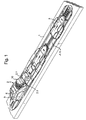
- FIG 1 illustrates a ski binding 2,3 fixed to the upper surface of a ski 1, where the ski binding comprises a front element having an engagement section 2.1 for pivotal engagement of a ski shoe engagement pin 21, and a rear binding element 3 for engagement with a slit in the underside of the heel of the ski shoe.
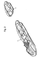
- the front and rear elements of the ski binding also appears from figure 2 .
- the ski have on its upper surface a ski binding fastening base element 1.1, e.g. a so called NIS-plate (Registered trade-mark), to which the front and rear binding elements 2,3 can be releasable fastened by snap fastening.
- NIS-plate Registered trade-mark
- adjustable positioning of the elements 2,3 along the ski becomes possible to adjust to the ski shoe size and the substantially vertical load on the ski.
- the base element 1.1 can be fastened to or integrated with a ski 1.
- the elements 2,3 be fastened to the ski by use of regular screws or other fastening means could be used.
- the engagement section 2.1 of the binding includes a first stationary engagement part 4 and a movable engagement part 5.
- a spring-loaded activation element 6 is also provided to move the movable engagement part 5 between a locking position and a release position of the ski shoe.
- a first housing section 7 exists having a bottom 7.1 and a pair of side elements 7.2 extending from the bottom 7.1 and providing bearing surfaces 7.3 for the fulcrum pins 6.1 of the activation element 6.
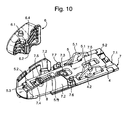
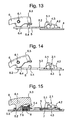
- the stationary engagement part 4 includes a base 4.1 and a pair of protruding elements 4.2, which at top have recesses 4.3 to provide the engagement section 2.1, as shown in more detail in figure 10-20 .
- the movable engagement part 5 is a slider in sliding engagement with the stationary engagement part 4 and in sliding engagement with slider guides 7.4 of the first housing section 7.
- the movable engagement part 5 includes at a rear area thereof a pair of protruding locking elements 5.1, e.g. hook shaped elements, extending from a base 5.2 of the movable engagement part 5.
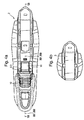
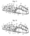
- Each locking element 5.1 in locking position for the movable engagement part 5 is positioned sideways in relation to adjacent recess 4.3 on the stationary engagement section 4 to provide in co-operation with said recess 4.3 a means for locking the engagement pin 21, see figure 11 , 13 , 15 , 17 and 20 .
- Each locking element 5.1 in ski shoe releasing position of the movable engagement part 5 is positioned forward in relation to the adjacent recess 4.3 of the stationary engagement part 4, that is, displaced from the recess 4.3 in the lengthwise direction of the binding, see figures 12 , 14 , 16 and 18 .
- Activation element 6 includes a button 6.2 extending downwards to directly engage an forward positioned opening 5.3 in the slider, whereby the slider 5 is slided forward to a releasing position by a downwards pushing operation on the activation element 6 at a position behind its fulcrum pins 6.1.
- a spring 8 is positioned between an abutment 7.5 at the bottom 7.1 of the first housing section 7 and an abutment 5.4 on the slider shaped movable engagement part 5 to provide spring loading of the movable engagement part 5 and the activation element 6.
- the stationary engagement part 4 is positioned under the slider shaped movable engagement part 5 and rests on the bottom 7.1 of the first housing section, whereby the movable engagement part 5 at its front area is sliding on top of the bottom 7.1 of the first housing section 7 and at its rear area slides on top of the stationary engagement section 4.
- the stationary engagement part 4 is positioned above the slider shaped movable engagement section 5, and the stationary engagement section 4 has feet or other types of fastening means (not clearly shown) resting on the bottom 7.1 of the first housing section 7, whereby the movable engagement part 5 on its underside is sliding on the bottom 7.1 of the first housing section 7 and with its upper surface of its rear area sliding connects with a underside surface of the stationary engagement part 4.
- the element 6 acts as a release mechanism, and due to the button 6.2 co-operating with opening 5.3 of the movable engagement part 5, and the part 5 is spring-loaded by the spring 8, element 6 is also spring-loaded. It should be noted that the outside of engagement pocket 7.5 constitute one of the guides 7.4 for part 5.
- element 6 is arranged to directly exert a force on the movable engagement section 5, that in reality constitutes a ski shoe fastening element.
- fulcrum pins 6.1 By activation of the release element 6 by exertion of a release force, e.g. by utilizing the pointed end of a ski pole; on position 6.2, is a substantial stress applied the fulcrum pins 6.1 from the bearing surfaces 7.3 on the side elements 7.2 provided a remedy is provided to reduce such stress.
- a remedy is provided to reduce such stress.
- Figure 21 illustrates the sole of a ski shoe or ski boot wherein the front area of the sole comprises an engagement pin 21 attached to the ski binding 2, whereby the engagement pin is lies in the engagement section 2.1 and is locked by locking element 5.1.
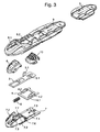
- a second housing part 9 As indicated in the exploded view of figure 3 is a second housing part 9 provided, the second housing section 9 being adapted to snap connection from above on the first housing section 7.
- the second housing section 9 has at a front area thereof a pair of recesses 9.1 for pivotal engagement with an upper part of the fulcrum pins 6.1.
- the second housing section 9 effects that the fulcrum pins 6.1 of the element 6 is limited in upwards movement, and also effects that the stationary and movable engagement element 5, 6 is limited in upwards movement.
- At least one resilient elements 10, 11 is fastenable to the second housing section 9, where at least one resilient element is fastenable in front of or behind the engagement section 2.1 for pivotal engagement of the ski shoe.
- the front resilient elements 10 is preferably fastenable to the second housing section 9 from underneath the second housing section 9, by utilizing pins on the underside of the element 10 to engage holes in flanges of element 10.
- the behind, or rear, resilient element 11 is fastenable to the second housing section from above by snap connection.
- the resilient elements 10, 11 is present to provide backwards and forwards biasing, respectively, of the rotation of the ski shoe.
- the resilient element 10, 11 aids to keep snow from entering the inner part of the ski binding.
- the elements 12, 13 in figure 3 is only plates of decorative and cover purposes and have no further functionality.
- the first housing section 7, the stationary engagement part 4, the movable engagement part 5, the spring 8, the activation element 6, and the second housing section 9, all capable of being assembled by successive vertical directed mounting steps.
- ski binding of the present invention can also be assembled by following steps:
- Step c) of either of the above disclosed methods comprises positioning the stationary engagement part 4 prior to providing the movable engagement part 5, as illustrated in figures 3 and 10-16 .
- step c) comprise positioning the movable engagement part 5 prior to positioning the stationary engagement part 4.
- the resilient element 10 is inserted from below in front of the engagement section 2.1 in the opening 9.2 of the second housing section 9 prior to performing step e), and the element can have holes adapted for tight fitting on pins on underneath the second housing section 9.
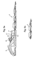
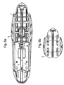
- FIGS 4a-9 are merely attached to illustrate how the invention can be utilized industrially, with additional guidance from the exploded view of figure 3 , and the detail of the release- and ski boot fastening mechanism illustrated in figures 10-21 .
Landscapes
- Footwear And Its Accessory, Manufacturing Method And Apparatuses (AREA)
- Fittings On The Vehicle Exterior For Carrying Loads, And Devices For Holding Or Mounting Articles (AREA)
- Professional, Industrial, Or Sporting Protective Garments (AREA)
- Tires In General (AREA)
Claims (17)
- Fixation de ski de fond ou de randonnée à ski, comprenant:- une section d'engagement (2.1) pour l'engagement à pivotement d'une broche d'engagement de la chaussure de ski (21), la section d'engagement comprenant une portion d'engagement stationnaire (4) et une portion d'engagement mobile (5); la portion d'engagement stationnaire (4) comprenant une base (4.1) et une paire d'éléments en saillie (4.2), la partie distale des éléments en saillie (4.2) étant pourvue d'un évidement (4.3) adapté de manière à recevoir la broche d'engagement de la chaussure de ski; et la portion d'engagement mobile (5) étant un coulisseau en prise glissante avec la portion d'engagement stationnaire (4);- un élément d'activation (6) adapté de manière à déplacer la portion d'engagement mobile (5) entre une position de verrouillage et une position de libération de la broche d'engagement; et- un bouton orienté vers le bas (6.2) arrangé sur l'élément d'activation (6) de manière à engager une ouverture (5.3) dans la portion d'engagement mobile, la portion d'engagement mobile (5) glissant en avant à la position de libération par une force vers le bas sur l'élément d'activation (6) à une position derrière les points d'appui (6.1) de l'élément d'activation,caractérisée en ce que- lors de l'usage, la base (4.1) de la portion d'engagement stationnaire (4) est positionnée au-dessous de la partie d'engagement mobile (5) et repose sur une première section de boîtier (7), la portion d'engagement mobile (5), à sa zone avant, glissant au-dessus du fond d'une première section de boîtier (7), et, à sa zone arrière, glissant sur la partie d'engagement stationnaire (4).
- Fixation selon la revendication 1, dans laquelle la fixation en outre comprend au moins un élément de verrouillage (5.1) arrangé sur la portion d'engagement mobile (5) dans la position de verrouillage coopère avec les évidements (4.3) pour fournir un moyen de verrouillage de la broche d'engagement (21); et l'au moins un élément de verrouillage (5.1) dans la position de libération est déplacé à partir des évidements (4.3) dans la direction longitudinale de la fixation.
- Fixation selon la revendication 1, dans laquelle la fixation en outre comprend un ressort (8) arrangé entre une butée (7.5) au fond (7.1) de la première section de boîtier (7) et une butée (5.4) sur la partie d'engagement mobile (5) pour fournir un chargement de ressort de la portion d'engagement mobile (5) et de l'élément d'activation (6).
- Fixation selon l'une quelconque des revendications précédentes, dans laquelle une deuxième section de boîtier (9) est pourvue, la deuxième section de boîtier étant adaptée à une liaison à attache rapide d'enclenchement avec la première section de boîtier (7).
- Fixation selon la revendication 1, dans laquelle la zone avant de la deuxième section de boîtier (9) est pourvue de deux évidements (9.1) constituant un engagement à pivotement avec la partie supérieure des points d'appui (6.1).
- Fixation selon la revendication 1, dans laquelle la deuxième section de boîtier (9) est pourvue d'une ouverture (9.2) pour loger la paire d'éléments en saillie (4.2) et l'au moins un élément de verrouillage (5.1).
- Fixation selon la revendication 1, dans laquelle une première section de boîtier (7) est adaptée pour une fixation à bascule libérable et réglable sur un élément de base (1.1), l'élément de base (1.1) étant fixé à un ski, ou intégré avec celui-ci (1).
- Fixation selon la revendication 1, dans laquelle au moins un élément élastique (10;11) peut être fixé à la deuxième section de boîtier (9), l'au moins un élément élastique étant fixé, respectivement devant (10), ou derrière (11) la section d'engagement (2.1) pour l'engagement à pivotement de la chaussure de ski.
- Fixation selon la revendication 8, dans laquelle l'élément élastique avant (10) peut être fixé à la deuxième section de boîtier (9) de dessous de la deuxième section de boîtier (9).
- Fixation selon la revendication 8, dans laquelle l'élément élastique derrière (11) peut être fixé à la deuxième section de boîtier (9) de dessus de la deuxième section de boîtier (9).
- Fixation selon les revendications 1, 2 et 3, dans laquelle la première section de boîtier (7), le ressort (8), la portion d'engagement stationnaire (4), la portion d'engagement mobile (5), l'élément d'activation (6), et la deuxième section de boîtier (9) sont tous assemblés par des étapes successives de montage dirigé verticalement.
- Procédé d'assembler des parties fonctionnelles d'une fixation de ski de fond ou de randonnée à ski pour fournir une fixation pour l'engagement amovible avec un moyen d'engagement d'une chaussure de ski, comprenant les étapes consistant à:a) fournir une première section de boîtier (7);b) positionner, par un déplacement vertical vers le bas, une extrémité d'un ressort (8) à l'encontre d'une butée (7.5) de la première section de boîtier (7), le ressort s'étendant dans la direction longitudinale de la première section de boîtier (7);c) positionner, par des déplacements verticaux vers le bas, les portions d'engagement stationnaire (4) et mobile (5) sur un fond (7.1) de la première section de boîtier (7), la portion d'engagement mobile (5) étant arrangée en prise glissante avec des guides (7.4) de la première section de boîtier et en butée avec la deuxième extrémité du ressort (8);d) positionner, par un déplacement vertical vers le bas, un élément d'activation (6) sur une première section de boîtier (7), un bouton orienté vers le bas (6.2) de l'élément d'activation (6) étant arrangé en butée avec une ouverture (5.3) en face de la portion d'engagement mobile (5); ete) raccorder par un déplacement vertical vers le bas, une deuxième section de boîtier (9) sur la première section de boîtier (7) au moyen d'une liaison à attache rapide d'enclenchement.
- Procédé selon la revendication 12, dans lequel l'étape d) en outre comprend l'étape consistant à:positionner des points d'appui (6.1) de l'élément d'activation (6) dans des surfaces de palier (7.3) sur une paire d'éléments latéraux (7.2) s'étendant depuis la première section de boîtier (7).
- Procédé selon la revendication 12, dans lequel l'étape c) comprend l'étape consistant à positionner la portion d'engagement stationnaire (4) avant le positionnement de la portion d'engagement mobile (5).
- Procédé selon la revendication 12, dans lequel l'étape c) comprend l'étape consistant à positionner la portion d'engagement mobile (5) avant le positionnement de la portion d'engagement stationnaire (4).
- Procédé selon la revendication 12, dans lequel un élément élastique (10) est positionné par un déplacement vertical vers le bas sur la partie supérieure des portions d'engagement stationnaire et mobile (4,5) avant la mise en oeuvre de l'étape e).
- Procédé selon la revendication 12, dans lequel l'élément élastique (10) est positionné dans une ouverture (9.2) de la deuxième section de boîtier (9) avant la mise en oeuvre de l'étape e).
Priority Applications (1)
| Application Number | Priority Date | Filing Date | Title |
|---|---|---|---|
| PL11768182T PL2616151T3 (pl) | 2010-09-15 | 2011-09-15 | Wiązania do nart skitourowych lub biegowych |
Applications Claiming Priority (2)
| Application Number | Priority Date | Filing Date | Title |
|---|---|---|---|
| NO20101289A NO20101289A1 (no) | 2010-09-15 | 2010-09-15 | Langrennsbinding, samt fremgangsmate for sammenstilling av nevnte langrennsbinding |
| PCT/NO2011/000254 WO2012036562A1 (fr) | 2010-09-15 | 2011-09-15 | Fixation de ski de randonnée ou de ski de fond |
Publications (2)
| Publication Number | Publication Date |
|---|---|
| EP2616151A1 EP2616151A1 (fr) | 2013-07-24 |
| EP2616151B1 true EP2616151B1 (fr) | 2015-03-18 |
Family
ID=44789573
Family Applications (2)
| Application Number | Title | Priority Date | Filing Date |
|---|---|---|---|
| EP11768182.5A Not-in-force EP2616151B1 (fr) | 2010-09-15 | 2011-09-15 | Fixation de ski de fond ou de randonnee a ski |
| EP11768181.7A Not-in-force EP2616150B1 (fr) | 2010-09-15 | 2011-09-15 | Fixation de randonnée ou de ski de fond |
Family Applications After (1)
| Application Number | Title | Priority Date | Filing Date |
|---|---|---|---|
| EP11768181.7A Not-in-force EP2616150B1 (fr) | 2010-09-15 | 2011-09-15 | Fixation de randonnée ou de ski de fond |
Country Status (9)
| Country | Link |
|---|---|
| US (3) | US20130300088A1 (fr) |
| EP (2) | EP2616151B1 (fr) |
| CN (2) | CN103118748B (fr) |
| CA (2) | CA2811050C (fr) |
| EA (2) | EA024677B1 (fr) |
| NO (1) | NO20101289A1 (fr) |
| PL (2) | PL2616150T3 (fr) |
| UA (2) | UA109025C2 (fr) |
| WO (2) | WO2012036561A1 (fr) |
Families Citing this family (18)
| Publication number | Priority date | Publication date | Assignee | Title |
|---|---|---|---|---|
| NO20101289A1 (no) * | 2010-09-15 | 2012-03-16 | Rottefella As | Langrennsbinding, samt fremgangsmate for sammenstilling av nevnte langrennsbinding |
| CH705579A2 (de) * | 2011-09-29 | 2013-04-15 | Fritschi Ag Swiss Bindings | Frontautomat. |
| NO20130873A1 (no) * | 2013-06-24 | 2014-12-25 | Rottefella As | Monteringssystem for montering av bindinger på ski |
| NO336788B1 (no) | 2013-09-20 | 2015-11-02 | Rottefella As | Skibinding for turskigåing eller langrenn |
| US9649988B2 (en) * | 2014-12-30 | 2017-05-16 | Thule Sweden Ab | Ski carrier clamp |
| RU2621777C2 (ru) * | 2015-10-27 | 2017-06-07 | Роман Владимирович Шамов | Лыжное крепление р.в. шамова |
| RU2683768C2 (ru) * | 2016-01-29 | 2019-04-01 | Станислав Викторович Мозговой | Крепление для беговых лыж |
| USD820932S1 (en) * | 2016-05-04 | 2018-06-19 | Salomon S.A.S. | Ski binding |
| USD820933S1 (en) * | 2016-05-04 | 2018-06-19 | Salomon S.A.S. | Ski binding |
| AT519524A1 (de) * | 2016-12-19 | 2018-07-15 | Fischer Sports Gmbh | Langlaufbindung |
| AT519525B1 (de) * | 2016-12-19 | 2019-01-15 | Fischer Sports Gmbh | Langlauf- oder Tourenskibindung |
| FI12458U1 (fi) * | 2019-04-15 | 2019-09-13 | Tiitola Antti Jussi | Suksisiteeseen liitettävä sovitinosa |
| TWI728519B (zh) * | 2019-10-22 | 2021-05-21 | 張育愷 | 鞋用快拆模組及具有鞋用快拆模組的雪板裝置 |
| RU2727311C1 (ru) * | 2020-02-03 | 2020-07-21 | Роман Владимирович Шамов | Лыжное крепление |
| RU197293U1 (ru) * | 2020-02-03 | 2020-04-20 | Роман Владимирович Шамов | Фиксирующий механизм с перекрытием паза, в котором в рабочем состоянии располагается шпилька ботинка |
| RU198621U1 (ru) * | 2020-03-23 | 2020-07-21 | Роман Владимирович Шамов | Лыжное крепление |
| RU200169U1 (ru) * | 2020-03-23 | 2020-10-08 | Роман Владимирович Шамов | Кнопка для крепления лыжных ботинок |
| FR3145097B1 (fr) * | 2023-01-25 | 2025-03-14 | Rossignol Sa | Fixation pour ski nordique |
Family Cites Families (47)
| Publication number | Priority date | Publication date | Assignee | Title |
|---|---|---|---|---|
| FR2522512A1 (fr) * | 1982-03-05 | 1983-09-09 | Look Sa | Ensemble pour ski de fond |
| AT379748B (de) * | 1983-12-19 | 1986-02-25 | Amf Sport Freizeitgeraete | Sicherheits-skibindung |
| IT1180969B (it) * | 1984-04-11 | 1987-09-23 | Tessaro Mario Matess | Attacco per sci da fondo autobloccante il puntale della calzatura |
| FR2582226B1 (fr) * | 1985-05-24 | 1987-06-26 | Look Sa | Fixation pour ski de fond |
| FR2598933B1 (fr) * | 1986-05-22 | 1988-08-26 | Salomon Sa | Fixation de securite d'une chaussure sur un ski |
| IT1189885B (it) * | 1986-06-20 | 1988-02-10 | Olivieri Icaro & C | Puntale per scarpe per sci di fondo |
| FR2632539A1 (fr) * | 1988-06-09 | 1989-12-15 | Salomon Sa | Fixation de ski de fond |
| FR2634134B1 (fr) * | 1988-07-13 | 1992-01-17 | Salomon Sa | Fixation de ski de fond |
| FR2634132B1 (fr) * | 1988-07-13 | 1992-10-23 | Salomon Sa | Dispositif de fixation notamment pour chaussure de ski de fond |
| US5224729A (en) * | 1988-07-13 | 1993-07-06 | Salomon S.A. | Cross-country ski binding |
| DE3915531A1 (de) * | 1988-07-13 | 1990-01-18 | Salomon Sa | Langlaufskibindung |
| FR2635014B1 (fr) * | 1988-08-05 | 1990-10-12 | Salomon Sa | Fixation de ski de fond a fermeture automatique |
| FR2638974B1 (fr) * | 1988-08-16 | 1990-09-21 | Salomon Sa | Fixation de ski de fond de type charniere |
| IT1225976B (it) * | 1988-09-19 | 1990-12-10 | Olivieri Icaro & C | Attacco integrato per sci da fondo. |
| FR2643608B1 (fr) * | 1989-02-27 | 1991-01-11 | Rossignol Sa | |
| FR2645764B1 (fr) * | 1989-04-12 | 1991-06-14 | Salomon Sa | Fixation pour ski de fond |
| FR2645758B1 (fr) * | 1989-04-12 | 1991-06-14 | Salomon Sa | Dispositif de fixation d'une chaussure a un ski de fond |
| FR2650192B1 (fr) * | 1989-07-28 | 1991-10-25 | Salomon Sa | Fixation pour ski de fond et tampon elastique destine a une telle fixation |
| DE4010929A1 (de) * | 1990-04-04 | 1991-10-10 | Walter Dekanovsky | Langlaufskibindung |
| DE9200453U1 (de) * | 1992-01-16 | 1992-03-05 | Rottefella AS, Oslo/Osló | Langlauf- oder Tourenskibindung für Langlaufskischuhe |
| AT397474B (de) | 1992-03-31 | 1994-04-25 | Brandhuber Alfred | Skilanglaufbindung |
| DE4343485C1 (de) * | 1993-09-14 | 1995-03-30 | Rottefella As | Anordnung einer Langlaufskibindung |
| FR2739788B1 (fr) * | 1995-10-16 | 1997-12-12 | Salomon Sa | Ensemble de fixation d'une chaussure a un organe de glisse |
| US5669622A (en) * | 1995-02-08 | 1997-09-23 | Miller; Michael E. | Ski binding |
| EP0830185B1 (fr) * | 1995-06-06 | 2001-07-04 | Rottefella A/S | Dispositif pour fixation de ski de fond, en particulier pour la pratique du patinage |
| US5690351A (en) | 1995-07-21 | 1997-11-25 | Karol; Chris | Snowboard binding system |
| FR2738158B1 (fr) * | 1995-09-06 | 1997-10-17 | Salomon Sa | Dispositif de fixation |
| FR2741543A1 (fr) * | 1995-11-27 | 1997-05-30 | Bibollet Jean Claude | Fixations pour ski de fond |
| FR2742060B1 (fr) | 1995-12-08 | 1998-01-09 | Salomon Sa | Dispositif de fixation d'une chaussure a un article de sport |
| DE19623825C1 (de) * | 1996-06-14 | 1998-01-08 | Rottefella As | Langlauf- oder Tourenskibindung |
| DE19809729A1 (de) * | 1998-03-06 | 1999-09-09 | Rottefella As | Langlauf- oder Tourenskibindung |
| US6623027B1 (en) * | 1998-06-15 | 2003-09-23 | Bryce Wheeler | Release binding and brake for telemark and cross-country skis |
| FR2788992B1 (fr) * | 1999-02-02 | 2001-04-06 | Look Fixations Sa | Ensemble chaussure-fixation de ski de securite |
| AT411018B (de) | 2001-04-11 | 2003-09-25 | Fischer Gmbh | Skibindung für langlauf- und tourenski |
| US7207591B2 (en) * | 2001-05-08 | 2007-04-24 | Rottefella As | Ski binding |
| FR2834473B1 (fr) * | 2002-01-04 | 2004-08-13 | Salomon Sa | Fixation de ski de fond |
| AT412191B (de) * | 2002-04-11 | 2004-11-25 | Fischer Gmbh | Skibindung, insbesondere für den langlauf |
| AT412949B (de) | 2002-12-05 | 2005-09-26 | Fischer Gmbh | Langlaufbindung |
| FR2856312B1 (fr) * | 2003-06-18 | 2005-08-05 | Salomon Sa | Dispositif de fixation a bras pivotant |
| FR2873044B1 (fr) * | 2004-07-13 | 2006-09-29 | Salomon Sa | Dispositif de fixation d'une chaussure a un article de sport avec systeme de rappel elastique separe |
| DE102005026725A1 (de) | 2005-02-04 | 2006-06-14 | Rottefella As | Langlauf-oder Tourenskibindung |
| CN100571825C (zh) | 2005-02-04 | 2009-12-23 | 罗特费尔拉公司 | 越野滑雪或旋转滑雪的滑雪板固定器 |
| FR2882658B1 (fr) | 2005-03-07 | 2007-05-04 | Salomon Sa | Dispositif de fixation a double commande |
| FR2910337B1 (fr) * | 2006-12-20 | 2009-06-05 | Salomon Sa | Article comprenant un bouton mobile entre au moins deux positions |
| WO2011006544A1 (fr) * | 2009-07-17 | 2011-01-20 | Rottefella As | Fléchisseur à pince de fixation |
| WO2011006542A1 (fr) * | 2009-07-17 | 2011-01-20 | Rottefella As | Fléchisseur à bras fléchisseur étendu |
| NO20101289A1 (no) * | 2010-09-15 | 2012-03-16 | Rottefella As | Langrennsbinding, samt fremgangsmate for sammenstilling av nevnte langrennsbinding |
-
2010
- 2010-09-15 NO NO20101289A patent/NO20101289A1/no not_active Application Discontinuation
-
2011
- 2011-09-15 WO PCT/NO2011/000253 patent/WO2012036561A1/fr not_active Ceased
- 2011-09-15 WO PCT/NO2011/000254 patent/WO2012036562A1/fr not_active Ceased
- 2011-09-15 CN CN201180044667.6A patent/CN103118748B/zh not_active Expired - Fee Related
- 2011-09-15 US US13/822,679 patent/US20130300088A1/en not_active Abandoned
- 2011-09-15 UA UAA201304649A patent/UA109025C2/en unknown
- 2011-09-15 EP EP11768182.5A patent/EP2616151B1/fr not_active Not-in-force
- 2011-09-15 US US13/822,678 patent/US9126095B2/en not_active Expired - Fee Related
- 2011-09-15 CA CA2811050A patent/CA2811050C/fr not_active Expired - Fee Related
- 2011-09-15 UA UAA201304650A patent/UA109026C2/en unknown
- 2011-09-15 PL PL11768181T patent/PL2616150T3/pl unknown
- 2011-09-15 EA EA201390385A patent/EA024677B1/ru not_active IP Right Cessation
- 2011-09-15 CA CA2811051A patent/CA2811051C/fr not_active Expired - Fee Related
- 2011-09-15 EP EP11768181.7A patent/EP2616150B1/fr not_active Not-in-force
- 2011-09-15 PL PL11768182T patent/PL2616151T3/pl unknown
- 2011-09-15 CN CN201180044361.0A patent/CN103108679B/zh not_active Expired - Fee Related
- 2011-09-15 EA EA201390379A patent/EA025472B1/ru not_active IP Right Cessation
-
2015
- 2015-04-13 US US14/684,723 patent/US9320961B2/en not_active Expired - Fee Related
Also Published As
| Publication number | Publication date |
|---|---|
| US20130300088A1 (en) | 2013-11-14 |
| CN103118748B (zh) | 2015-04-29 |
| US9320961B2 (en) | 2016-04-26 |
| US9126095B2 (en) | 2015-09-08 |
| WO2012036561A1 (fr) | 2012-03-22 |
| CA2811051C (fr) | 2019-01-15 |
| EA201390385A1 (ru) | 2013-08-30 |
| NO20101289A1 (no) | 2012-03-16 |
| EP2616151A1 (fr) | 2013-07-24 |
| WO2012036562A1 (fr) | 2012-03-22 |
| PL2616150T3 (pl) | 2015-08-31 |
| UA109026C2 (en) | 2015-07-10 |
| US20150209651A1 (en) | 2015-07-30 |
| CA2811051A1 (fr) | 2012-03-22 |
| CN103118748A (zh) | 2013-05-22 |
| EA201390379A1 (ru) | 2013-07-30 |
| CA2811050A1 (fr) | 2012-03-22 |
| PL2616151T3 (pl) | 2015-08-31 |
| EA024677B1 (ru) | 2016-10-31 |
| UA109025C2 (en) | 2015-07-10 |
| EP2616150B1 (fr) | 2015-03-18 |
| US20130313807A1 (en) | 2013-11-28 |
| CN103108679B (zh) | 2015-07-29 |
| EP2616150A1 (fr) | 2013-07-24 |
| EA025472B1 (ru) | 2016-12-30 |
| CN103108679A (zh) | 2013-05-15 |
| CA2811050C (fr) | 2018-10-02 |
Similar Documents
| Publication | Publication Date | Title |
|---|---|---|
| EP2616151B1 (fr) | Fixation de ski de fond ou de randonnee a ski | |
| US8439389B2 (en) | Toe unit for alpine touring binding | |
| US9566498B2 (en) | Ski binding for touring or cross-country skiing | |
| US8746729B2 (en) | Toe piece for gliding apparatus and gliding apparatus equipped with such binding | |
| EP2682165B1 (fr) | Fixation entre un ski et une chaussure de ski | |
| US20100257754A1 (en) | Ski-boot with means for actuating corresponding engaging members of ski-touring bindings | |
| EP2135645B1 (fr) | Fixation de ski démontable |
Legal Events
| Date | Code | Title | Description |
|---|---|---|---|
| PUAI | Public reference made under article 153(3) epc to a published international application that has entered the european phase |
Free format text: ORIGINAL CODE: 0009012 |
|
| 17P | Request for examination filed |
Effective date: 20130410 |
|
| AK | Designated contracting states |
Kind code of ref document: A1 Designated state(s): AL AT BE BG CH CY CZ DE DK EE ES FI FR GB GR HR HU IE IS IT LI LT LU LV MC MK MT NL NO PL PT RO RS SE SI SK SM TR |
|
| DAX | Request for extension of the european patent (deleted) | ||
| REG | Reference to a national code |
Ref country code: DE Ref legal event code: R079 Ref document number: 602011014858 Country of ref document: DE Free format text: PREVIOUS MAIN CLASS: A63C0009086000 Ipc: A63C0009000000 |
|
| RIC1 | Information provided on ipc code assigned before grant |
Ipc: A63C 9/08 20120101ALI20140825BHEP Ipc: A63C 9/20 20120101ALN20140825BHEP Ipc: A63C 9/086 20120101ALI20140825BHEP Ipc: A63C 9/00 20120101AFI20140825BHEP |
|
| GRAP | Despatch of communication of intention to grant a patent |
Free format text: ORIGINAL CODE: EPIDOSNIGR1 |
|
| INTG | Intention to grant announced |
Effective date: 20141006 |
|
| RIC1 | Information provided on ipc code assigned before grant |
Ipc: A63C 9/086 20120101ALI20140923BHEP Ipc: A63C 9/08 20120101ALI20140923BHEP Ipc: A63C 9/20 20120101ALN20140923BHEP Ipc: A63C 9/00 20120101AFI20140923BHEP |
|
| RIN1 | Information on inventor provided before grant (corrected) |
Inventor name: WOELLO, EVEN Inventor name: SVENDSEN, OEYVAR Inventor name: PETTERSEN, AKSEL Inventor name: HOLM, THOMAS |
|
| GRAS | Grant fee paid |
Free format text: ORIGINAL CODE: EPIDOSNIGR3 |
|
| GRAA | (expected) grant |
Free format text: ORIGINAL CODE: 0009210 |
|
| AK | Designated contracting states |
Kind code of ref document: B1 Designated state(s): AL AT BE BG CH CY CZ DE DK EE ES FI FR GB GR HR HU IE IS IT LI LT LU LV MC MK MT NL NO PL PT RO RS SE SI SK SM TR |
|
| REG | Reference to a national code |
Ref country code: GB Ref legal event code: FG4D |
|
| REG | Reference to a national code |
Ref country code: CH Ref legal event code: EP |
|
| REG | Reference to a national code |
Ref country code: IE Ref legal event code: FG4D |
|
| REG | Reference to a national code |
Ref country code: AT Ref legal event code: REF Ref document number: 716163 Country of ref document: AT Kind code of ref document: T Effective date: 20150415 |
|
| REG | Reference to a national code |
Ref country code: DE Ref legal event code: R096 Ref document number: 602011014858 Country of ref document: DE Effective date: 20150430 |
|
| REG | Reference to a national code |
Ref country code: SE Ref legal event code: TRGR |
|
| REG | Reference to a national code |
Ref country code: CH Ref legal event code: NV Representative=s name: HEPP WENGER RYFFEL AG, CH |
|
| REG | Reference to a national code |
Ref country code: NO Ref legal event code: T2 Effective date: 20150318 |
|
| REG | Reference to a national code |
Ref country code: NL Ref legal event code: VDEP Effective date: 20150318 |
|
| REG | Reference to a national code |
Ref country code: NL Ref legal event code: VDEP Effective date: 20150318 |
|
| PG25 | Lapsed in a contracting state [announced via postgrant information from national office to epo] |
Ref country code: HR Free format text: LAPSE BECAUSE OF FAILURE TO SUBMIT A TRANSLATION OF THE DESCRIPTION OR TO PAY THE FEE WITHIN THE PRESCRIBED TIME-LIMIT Effective date: 20150318 Ref country code: LT Free format text: LAPSE BECAUSE OF FAILURE TO SUBMIT A TRANSLATION OF THE DESCRIPTION OR TO PAY THE FEE WITHIN THE PRESCRIBED TIME-LIMIT Effective date: 20150318 |
|
| REG | Reference to a national code |
Ref country code: LT Ref legal event code: MG4D |
|
| PG25 | Lapsed in a contracting state [announced via postgrant information from national office to epo] |
Ref country code: LV Free format text: LAPSE BECAUSE OF FAILURE TO SUBMIT A TRANSLATION OF THE DESCRIPTION OR TO PAY THE FEE WITHIN THE PRESCRIBED TIME-LIMIT Effective date: 20150318 Ref country code: RS Free format text: LAPSE BECAUSE OF FAILURE TO SUBMIT A TRANSLATION OF THE DESCRIPTION OR TO PAY THE FEE WITHIN THE PRESCRIBED TIME-LIMIT Effective date: 20150318 Ref country code: GR Free format text: LAPSE BECAUSE OF FAILURE TO SUBMIT A TRANSLATION OF THE DESCRIPTION OR TO PAY THE FEE WITHIN THE PRESCRIBED TIME-LIMIT Effective date: 20150619 |
|
| REG | Reference to a national code |
Ref country code: PL Ref legal event code: T3 |
|
| PG25 | Lapsed in a contracting state [announced via postgrant information from national office to epo] |
Ref country code: NL Free format text: LAPSE BECAUSE OF FAILURE TO SUBMIT A TRANSLATION OF THE DESCRIPTION OR TO PAY THE FEE WITHIN THE PRESCRIBED TIME-LIMIT Effective date: 20150318 |
|
| REG | Reference to a national code |
Ref country code: SK Ref legal event code: T3 Ref document number: E 18915 Country of ref document: SK |
|
| PG25 | Lapsed in a contracting state [announced via postgrant information from national office to epo] |
Ref country code: ES Free format text: LAPSE BECAUSE OF FAILURE TO SUBMIT A TRANSLATION OF THE DESCRIPTION OR TO PAY THE FEE WITHIN THE PRESCRIBED TIME-LIMIT Effective date: 20150318 Ref country code: RO Free format text: LAPSE BECAUSE OF FAILURE TO SUBMIT A TRANSLATION OF THE DESCRIPTION OR TO PAY THE FEE WITHIN THE PRESCRIBED TIME-LIMIT Effective date: 20150318 Ref country code: PT Free format text: LAPSE BECAUSE OF FAILURE TO SUBMIT A TRANSLATION OF THE DESCRIPTION OR TO PAY THE FEE WITHIN THE PRESCRIBED TIME-LIMIT Effective date: 20150720 Ref country code: EE Free format text: LAPSE BECAUSE OF FAILURE TO SUBMIT A TRANSLATION OF THE DESCRIPTION OR TO PAY THE FEE WITHIN THE PRESCRIBED TIME-LIMIT Effective date: 20150318 |
|
| PG25 | Lapsed in a contracting state [announced via postgrant information from national office to epo] |
Ref country code: IS Free format text: LAPSE BECAUSE OF FAILURE TO SUBMIT A TRANSLATION OF THE DESCRIPTION OR TO PAY THE FEE WITHIN THE PRESCRIBED TIME-LIMIT Effective date: 20150718 |
|
| REG | Reference to a national code |
Ref country code: DE Ref legal event code: R097 Ref document number: 602011014858 Country of ref document: DE |
|
| PLBE | No opposition filed within time limit |
Free format text: ORIGINAL CODE: 0009261 |
|
| STAA | Information on the status of an ep patent application or granted ep patent |
Free format text: STATUS: NO OPPOSITION FILED WITHIN TIME LIMIT |
|
| PG25 | Lapsed in a contracting state [announced via postgrant information from national office to epo] |
Ref country code: DK Free format text: LAPSE BECAUSE OF FAILURE TO SUBMIT A TRANSLATION OF THE DESCRIPTION OR TO PAY THE FEE WITHIN THE PRESCRIBED TIME-LIMIT Effective date: 20150318 |
|
| REG | Reference to a national code |
Ref country code: AT Ref legal event code: UEP Ref document number: 716163 Country of ref document: AT Kind code of ref document: T Effective date: 20150318 |
|
| 26N | No opposition filed |
Effective date: 20151221 |
|
| PG25 | Lapsed in a contracting state [announced via postgrant information from national office to epo] |
Ref country code: SI Free format text: LAPSE BECAUSE OF FAILURE TO SUBMIT A TRANSLATION OF THE DESCRIPTION OR TO PAY THE FEE WITHIN THE PRESCRIBED TIME-LIMIT Effective date: 20150318 |
|
| PG25 | Lapsed in a contracting state [announced via postgrant information from national office to epo] |
Ref country code: MC Free format text: LAPSE BECAUSE OF FAILURE TO SUBMIT A TRANSLATION OF THE DESCRIPTION OR TO PAY THE FEE WITHIN THE PRESCRIBED TIME-LIMIT Effective date: 20150318 Ref country code: LU Free format text: LAPSE BECAUSE OF FAILURE TO SUBMIT A TRANSLATION OF THE DESCRIPTION OR TO PAY THE FEE WITHIN THE PRESCRIBED TIME-LIMIT Effective date: 20150915 |
|
| GBPC | Gb: european patent ceased through non-payment of renewal fee |
Effective date: 20150915 |
|
| REG | Reference to a national code |
Ref country code: IE Ref legal event code: MM4A |
|
| PG25 | Lapsed in a contracting state [announced via postgrant information from national office to epo] |
Ref country code: GB Free format text: LAPSE BECAUSE OF NON-PAYMENT OF DUE FEES Effective date: 20150915 Ref country code: IE Free format text: LAPSE BECAUSE OF NON-PAYMENT OF DUE FEES Effective date: 20150915 |
|
| REG | Reference to a national code |
Ref country code: FR Ref legal event code: PLFP Year of fee payment: 6 |
|
| PG25 | Lapsed in a contracting state [announced via postgrant information from national office to epo] |
Ref country code: BE Free format text: LAPSE BECAUSE OF FAILURE TO SUBMIT A TRANSLATION OF THE DESCRIPTION OR TO PAY THE FEE WITHIN THE PRESCRIBED TIME-LIMIT Effective date: 20150318 |
|
| PGFP | Annual fee paid to national office [announced via postgrant information from national office to epo] |
Ref country code: IT Payment date: 20160921 Year of fee payment: 6 Ref country code: CH Payment date: 20160914 Year of fee payment: 6 |
|
| PGFP | Annual fee paid to national office [announced via postgrant information from national office to epo] |
Ref country code: PL Payment date: 20160812 Year of fee payment: 6 Ref country code: CZ Payment date: 20160823 Year of fee payment: 6 Ref country code: SK Payment date: 20160815 Year of fee payment: 6 |
|
| PG25 | Lapsed in a contracting state [announced via postgrant information from national office to epo] |
Ref country code: MT Free format text: LAPSE BECAUSE OF FAILURE TO SUBMIT A TRANSLATION OF THE DESCRIPTION OR TO PAY THE FEE WITHIN THE PRESCRIBED TIME-LIMIT Effective date: 20150318 |
|
| PG25 | Lapsed in a contracting state [announced via postgrant information from national office to epo] |
Ref country code: HU Free format text: LAPSE BECAUSE OF FAILURE TO SUBMIT A TRANSLATION OF THE DESCRIPTION OR TO PAY THE FEE WITHIN THE PRESCRIBED TIME-LIMIT; INVALID AB INITIO Effective date: 20110915 Ref country code: BG Free format text: LAPSE BECAUSE OF FAILURE TO SUBMIT A TRANSLATION OF THE DESCRIPTION OR TO PAY THE FEE WITHIN THE PRESCRIBED TIME-LIMIT Effective date: 20150318 Ref country code: SM Free format text: LAPSE BECAUSE OF FAILURE TO SUBMIT A TRANSLATION OF THE DESCRIPTION OR TO PAY THE FEE WITHIN THE PRESCRIBED TIME-LIMIT Effective date: 20150318 |
|
| PG25 | Lapsed in a contracting state [announced via postgrant information from national office to epo] |
Ref country code: CY Free format text: LAPSE BECAUSE OF FAILURE TO SUBMIT A TRANSLATION OF THE DESCRIPTION OR TO PAY THE FEE WITHIN THE PRESCRIBED TIME-LIMIT Effective date: 20150318 |
|
| REG | Reference to a national code |
Ref country code: FR Ref legal event code: PLFP Year of fee payment: 7 |
|
| PG25 | Lapsed in a contracting state [announced via postgrant information from national office to epo] |
Ref country code: CZ Free format text: LAPSE BECAUSE OF NON-PAYMENT OF DUE FEES Effective date: 20170915 |
|
| REG | Reference to a national code |
Ref country code: CH Ref legal event code: PL |
|
| REG | Reference to a national code |
Ref country code: SK Ref legal event code: MM4A Ref document number: E 18915 Country of ref document: SK Effective date: 20170915 |
|
| PG25 | Lapsed in a contracting state [announced via postgrant information from national office to epo] |
Ref country code: TR Free format text: LAPSE BECAUSE OF FAILURE TO SUBMIT A TRANSLATION OF THE DESCRIPTION OR TO PAY THE FEE WITHIN THE PRESCRIBED TIME-LIMIT Effective date: 20150318 Ref country code: MK Free format text: LAPSE BECAUSE OF FAILURE TO SUBMIT A TRANSLATION OF THE DESCRIPTION OR TO PAY THE FEE WITHIN THE PRESCRIBED TIME-LIMIT Effective date: 20150318 |
|
| PG25 | Lapsed in a contracting state [announced via postgrant information from national office to epo] |
Ref country code: CH Free format text: LAPSE BECAUSE OF NON-PAYMENT OF DUE FEES Effective date: 20170930 Ref country code: LI Free format text: LAPSE BECAUSE OF NON-PAYMENT OF DUE FEES Effective date: 20170930 Ref country code: SK Free format text: LAPSE BECAUSE OF NON-PAYMENT OF DUE FEES Effective date: 20170915 |
|
| REG | Reference to a national code |
Ref country code: FR Ref legal event code: PLFP Year of fee payment: 8 |
|
| PG25 | Lapsed in a contracting state [announced via postgrant information from national office to epo] |
Ref country code: IT Free format text: LAPSE BECAUSE OF NON-PAYMENT OF DUE FEES Effective date: 20170915 |
|
| PG25 | Lapsed in a contracting state [announced via postgrant information from national office to epo] |
Ref country code: AL Free format text: LAPSE BECAUSE OF FAILURE TO SUBMIT A TRANSLATION OF THE DESCRIPTION OR TO PAY THE FEE WITHIN THE PRESCRIBED TIME-LIMIT Effective date: 20150318 |
|
| PG25 | Lapsed in a contracting state [announced via postgrant information from national office to epo] |
Ref country code: PL Free format text: LAPSE BECAUSE OF NON-PAYMENT OF DUE FEES Effective date: 20170915 |
|
| PGFP | Annual fee paid to national office [announced via postgrant information from national office to epo] |
Ref country code: SE Payment date: 20190910 Year of fee payment: 9 Ref country code: DE Payment date: 20190903 Year of fee payment: 9 Ref country code: FI Payment date: 20190909 Year of fee payment: 9 |
|
| PGFP | Annual fee paid to national office [announced via postgrant information from national office to epo] |
Ref country code: FR Payment date: 20200826 Year of fee payment: 10 |
|
| PGFP | Annual fee paid to national office [announced via postgrant information from national office to epo] |
Ref country code: AT Payment date: 20200825 Year of fee payment: 10 |
|
| REG | Reference to a national code |
Ref country code: DE Ref legal event code: R119 Ref document number: 602011014858 Country of ref document: DE |
|
| REG | Reference to a national code |
Ref country code: FI Ref legal event code: MAE |
|
| PG25 | Lapsed in a contracting state [announced via postgrant information from national office to epo] |
Ref country code: FI Free format text: LAPSE BECAUSE OF NON-PAYMENT OF DUE FEES Effective date: 20200915 |
|
| PG25 | Lapsed in a contracting state [announced via postgrant information from national office to epo] |
Ref country code: DE Free format text: LAPSE BECAUSE OF NON-PAYMENT OF DUE FEES Effective date: 20210401 |
|
| PG25 | Lapsed in a contracting state [announced via postgrant information from national office to epo] |
Ref country code: SE Free format text: LAPSE BECAUSE OF NON-PAYMENT OF DUE FEES Effective date: 20200916 |
|
| REG | Reference to a national code |
Ref country code: SE Ref legal event code: EUG |
|
| PGFP | Annual fee paid to national office [announced via postgrant information from national office to epo] |
Ref country code: NO Payment date: 20210909 Year of fee payment: 11 |
|
| REG | Reference to a national code |
Ref country code: AT Ref legal event code: MM01 Ref document number: 716163 Country of ref document: AT Kind code of ref document: T Effective date: 20210915 |
|
| PG25 | Lapsed in a contracting state [announced via postgrant information from national office to epo] |
Ref country code: FR Free format text: LAPSE BECAUSE OF NON-PAYMENT OF DUE FEES Effective date: 20210930 |
|
| PG25 | Lapsed in a contracting state [announced via postgrant information from national office to epo] |
Ref country code: AT Free format text: LAPSE BECAUSE OF NON-PAYMENT OF DUE FEES Effective date: 20210915 |
|
| REG | Reference to a national code |
Ref country code: NO Ref legal event code: MMEP |
|
| PG25 | Lapsed in a contracting state [announced via postgrant information from national office to epo] |
Ref country code: NO Free format text: LAPSE BECAUSE OF NON-PAYMENT OF DUE FEES Effective date: 20220930 |