EP2616334B1 - Appareil pour la manipulation active de surfaces aérodynamiques - Google Patents
Appareil pour la manipulation active de surfaces aérodynamiques Download PDFInfo
- Publication number
- EP2616334B1 EP2616334B1 EP10859345.0A EP10859345A EP2616334B1 EP 2616334 B1 EP2616334 B1 EP 2616334B1 EP 10859345 A EP10859345 A EP 10859345A EP 2616334 B1 EP2616334 B1 EP 2616334B1
- Authority
- EP
- European Patent Office
- Prior art keywords
- linear actuator
- wing
- aircraft
- sliding
- span
- Prior art date
- Legal status (The legal status is an assumption and is not a legal conclusion. Google has not performed a legal analysis and makes no representation as to the accuracy of the status listed.)
- Active
Links
Images


Classifications
-
- B—PERFORMING OPERATIONS; TRANSPORTING
- B64—AIRCRAFT; AVIATION; COSMONAUTICS
- B64C—AEROPLANES; HELICOPTERS
- B64C27/00—Rotorcraft; Rotors peculiar thereto
- B64C27/54—Mechanisms for controlling blade adjustment or movement relative to rotor head, e.g. lag-lead movement
- B64C27/58—Transmitting means, e.g. interrelated with initiating means or means acting on blades
- B64C27/59—Transmitting means, e.g. interrelated with initiating means or means acting on blades mechanical
- B64C27/615—Transmitting means, e.g. interrelated with initiating means or means acting on blades mechanical including flaps mounted on blades
-
- B—PERFORMING OPERATIONS; TRANSPORTING
- B64—AIRCRAFT; AVIATION; COSMONAUTICS
- B64C—AEROPLANES; HELICOPTERS
- B64C27/00—Rotorcraft; Rotors peculiar thereto
- B64C27/001—Vibration damping devices
-
- F—MECHANICAL ENGINEERING; LIGHTING; HEATING; WEAPONS; BLASTING
- F16—ENGINEERING ELEMENTS AND UNITS; GENERAL MEASURES FOR PRODUCING AND MAINTAINING EFFECTIVE FUNCTIONING OF MACHINES OR INSTALLATIONS; THERMAL INSULATION IN GENERAL
- F16H—GEARING
- F16H21/00—Gearings comprising primarily only links or levers, with or without slides
- F16H21/10—Gearings comprising primarily only links or levers, with or without slides all movement being in, or parallel to, a single plane
- F16H21/44—Gearings comprising primarily only links or levers, with or without slides all movement being in, or parallel to, a single plane for conveying or interconverting oscillating or reciprocating motions
-
- B—PERFORMING OPERATIONS; TRANSPORTING
- B64—AIRCRAFT; AVIATION; COSMONAUTICS
- B64C—AEROPLANES; HELICOPTERS
- B64C27/00—Rotorcraft; Rotors peculiar thereto
- B64C27/54—Mechanisms for controlling blade adjustment or movement relative to rotor head, e.g. lag-lead movement
- B64C27/72—Means acting on blades
- B64C2027/7205—Means acting on blades on each blade individually, e.g. individual blade control [IBC]
- B64C2027/7261—Means acting on blades on each blade individually, e.g. individual blade control [IBC] with flaps
- B64C2027/7266—Means acting on blades on each blade individually, e.g. individual blade control [IBC] with flaps actuated by actuators
-
- Y—GENERAL TAGGING OF NEW TECHNOLOGICAL DEVELOPMENTS; GENERAL TAGGING OF CROSS-SECTIONAL TECHNOLOGIES SPANNING OVER SEVERAL SECTIONS OF THE IPC; TECHNICAL SUBJECTS COVERED BY FORMER USPC CROSS-REFERENCE ART COLLECTIONS [XRACs] AND DIGESTS
- Y02—TECHNOLOGIES OR APPLICATIONS FOR MITIGATION OR ADAPTATION AGAINST CLIMATE CHANGE
- Y02T—CLIMATE CHANGE MITIGATION TECHNOLOGIES RELATED TO TRANSPORTATION
- Y02T50/00—Aeronautics or air transport
- Y02T50/30—Wing lift efficiency
-
- Y—GENERAL TAGGING OF NEW TECHNOLOGICAL DEVELOPMENTS; GENERAL TAGGING OF CROSS-SECTIONAL TECHNOLOGIES SPANNING OVER SEVERAL SECTIONS OF THE IPC; TECHNICAL SUBJECTS COVERED BY FORMER USPC CROSS-REFERENCE ART COLLECTIONS [XRACs] AND DIGESTS
- Y02—TECHNOLOGIES OR APPLICATIONS FOR MITIGATION OR ADAPTATION AGAINST CLIMATE CHANGE
- Y02T—CLIMATE CHANGE MITIGATION TECHNOLOGIES RELATED TO TRANSPORTATION
- Y02T50/00—Aeronautics or air transport
- Y02T50/40—Weight reduction
-
- Y—GENERAL TAGGING OF NEW TECHNOLOGICAL DEVELOPMENTS; GENERAL TAGGING OF CROSS-SECTIONAL TECHNOLOGIES SPANNING OVER SEVERAL SECTIONS OF THE IPC; TECHNICAL SUBJECTS COVERED BY FORMER USPC CROSS-REFERENCE ART COLLECTIONS [XRACs] AND DIGESTS
- Y10—TECHNICAL SUBJECTS COVERED BY FORMER USPC
- Y10T—TECHNICAL SUBJECTS COVERED BY FORMER US CLASSIFICATION
- Y10T74/00—Machine element or mechanism
- Y10T74/18—Mechanical movements
- Y10T74/18888—Reciprocating to or from oscillating
- Y10T74/1892—Lever and slide
- Y10T74/18928—Straight line motions
-
- Y—GENERAL TAGGING OF NEW TECHNOLOGICAL DEVELOPMENTS; GENERAL TAGGING OF CROSS-SECTIONAL TECHNOLOGIES SPANNING OVER SEVERAL SECTIONS OF THE IPC; TECHNICAL SUBJECTS COVERED BY FORMER USPC CROSS-REFERENCE ART COLLECTIONS [XRACs] AND DIGESTS
- Y10—TECHNICAL SUBJECTS COVERED BY FORMER USPC
- Y10T—TECHNICAL SUBJECTS COVERED BY FORMER US CLASSIFICATION
- Y10T74/00—Machine element or mechanism
- Y10T74/20—Control lever and linkage systems
Definitions
- This disclosure relates in general to the field of heavier-than-air aircraft, and more particularly to an apparatus for actively manipulating aerodynamic surfaces.
- US6,499,690 B1 discloses displacements of output portions of a pair of piezoelectric actuators arranged spanwise in a flap drive apparatus are magnified by a displacement magnification mechanism so that a swing arm is driven in swinging fashion with large amplitude.
- a flap attached to the trailing edge of a blade by way of a connecting rod connected to a tip of the swing arm is driven in vertical angular displacement fashion.
- the displacement magnification mechanism possesses an eccentric shaft has a first shaft and second shaft with offset axes. An output portion is coupled to the first shaft, and an output portion is coupled to the second shaft.
- the swing arm is fixed to the eccentric shaft. Displacement of the output portions, of the actuators, in opposite phase results in a stable swing of the swing arm.
- an aircraft comprising the features of claim 2.
- FIG. 1 is a perspective view of an example embodiment of a helicopter 10 according to the present specification.
- helicopter 10 has a fuselage 12 and a main rotor assembly 14, which includes main rotor blades 16a-c and a main rotor shaft 18.
- Helicopter 10 may also include a tail rotor assembly 20, which generally includes tail rotor blades 22 and a tail rotor shaft 24.
- Main rotor blades 16a-c may rotate about a longitudinal axis 26 of main rotor shaft 18.
- Tail rotor blades may rotate about a longitudinal axis 28 of tail rotor shaft 24.
- flaps 32a-b and actuator systems 36a-b on main rotor blades 16a-b respectively. Not visible in Figure 1 are flap 32c and actuator system 36c on main rotor blade 16c.
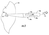
- FIG. 2 is a partial top view of helicopter 10, including main rotor blade 16a, connected to a hub 30 on main rotor shaft 18.
- main rotor blade 16a may include additional active elements that may be used to manipulate aerodynamic surfaces, such as flap 32a.
- Flap 32a in the example embodiment of helicopter 10 is placed outboard along the trailing edge 34a, but may be placed in other positions according to particular design criteria.
- flap 32a is illustrated and described herein as a distinct component of main rotor blade 16a, it may also be any movable or flexible portion of main rotor blade 16a.
- actuator system 36a is also depicted in the cut-away section Figure 2 , generally oriented parallel to a span-wise axis 17a of main rotor blade 16a.
- main rotor blade 16a may rotate about hub 30, while actuator system manipulates flap 32a.
- the rotation causes a number of reactive forces, including lift and centrifugal forces (CF).
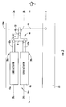
- FIG. 3 is a simple top-view schematic of actuator system 36a in main rotor blade 16a.
- Actuator system 36a includes linear actuators 38a-b.
- Each linear actuator 38a-b typically includes a fixed or stationary element, such as stators 40a-b, and a moving or sliding element, such as sliders 42a-b.
- Stators 40a-b in the example embodiment are rigidly connected to the frame of main rotor blade 16a, and they may be identical elements or may have distinct properties for certain applications.
- sliders 42a-b may be identical or have distinct properties for certain applications.
- Linear actuators 38a-b each has an elongated shape with a lengthwise axis 39a-b that is generally oriented parallel with span-wise axis 17a of main rotor blade 16a.
- linear actuators 38a-b are also generally oriented parallel to each other along the span of main rotor blade 16a.
- Such a span-wise orientation is generally preferable to other orientations as it generally provides larger space in the blade for larger, more powerful motors with longer strokes, and better mass placement.
- crank 44 is connected to sliders 42a-b.
- Crank 44 includes a beam element 46, a pivot element 48, and an arm element 50.
- pivot element 48 include a conventional bearing with rolling elements, an elastomeric element, a sleeve bushing, or a structural flexure.
- Pivot element 48 may be positioned coincident with beam element 46, or may be offset a distance L relative to beam element 46, as shown in Figure 3 .
- the negative spring effect may counteract aerodynamic forces and reduce actuator power requirements, thereby also potentially reducing the mass of actuator system 36a.
- Arm element 50 may be rigidly attached to beam element 46, or beam element 46 and arm element may 50 be fabricated as a single element.
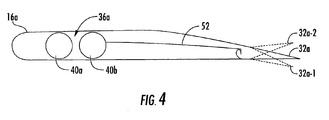
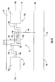
- FIG 4 is a simple side-view schematic of actuator system 36a.
- Stators 40a-b are preferably placed within the frame of main rotor blade 16a in parallel.
- Connecting rod 52 connects actuator system 36a to flap 32a through crank 44 (see Figure 3 ) and sliders 42a-b (see Figure 3 ).
- Flap 32a may rotate about an axis 33 in response to force from connecting rod 52. Alternate positions of flap 32a as it rotates about axis 33 are illustrated in phantom as flaps 32a-1 and 32a-2.
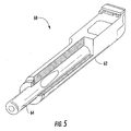
- FIG. 5 is a cut-away view of an example embodiment of a linear actuator 60.
- linear actuator 60 is an electromagnetic linear motor having a fixed element, stator 62, having electric coils, and an elongated, high-power permanent magnetic slider 64.
- the slider 64 moves and converts electrical power to useful work.
- the motion, position, and retention of slider 64 are controlled with electromagnetic force generated with the electric coils of stator 62.
- Such an actuator may provide benefits in certain applications where high bandwidth and large stroke with a small footprint are desirable.
- an electromagnetic motor such as linear actuator 60 may be advantageous in a helicopter rotor blade where vibrations and noise are counteracted with relatively small flap deflections at high frequency, but performance is enhanced with larger deflections at a lower frequency.
- Crank 44 is similar to a common bell crank, and as it rotates it converts the span-wise motion of sliders 42a-b into chord-wise motion that may be used to manipulate an active element, such as flap 32a, which is connected to arm element 50 through a connecting rod 52 or similar linkage.
- sliders 42a-b are actuated such that each reciprocates generally parallel to axis 17a and slider 42a moves opposite to slider 42b.
- slider 42a moves in the outboard direction of main rotor blade 16a
- slider 42b moves inboard.
- crank 44 rotates about pivot element 48, causing arm element 50 to advance toward trailing edge 34a of main rotor blade 16a.
- the movement of arm element 50 toward trailing edge 34a in turn causes connecting rod 52 to act on flap 32a, which may rotate about axis 33 to position 32a-1.
- crank 44 rotates in the opposite direction about pivot element 48, causing arm element 50 to retreat from trailing edge 34a.
- the movement of arm element 50 away from trailing edge 34b in turn causes connecting rod 52 to act on flap 32a, which may rotate about axis 33 to another position, such as 32a-2.
- FIG. 6 is a simple top-view schematic of another example embodiment of an actuator system 70 in a main rotor blade 72 according to the present specification.
- Actuator system 70 may include linear actuators 74a-b.
- Each linear actuator 74a-b typically includes a fixed or stationary element, such as stators 76a-b, and a moving element or sliding element, such as sliders 78a-b.
- Stators 76a-b in the example embodiment are rigidly connected to the frame of main rotor blade 72, and they may be identical elements or may have distinct properties for certain applications.
- sliders 78a-b may be identical or have distinct properties for certain applications.
- Linear actuators 74a-b each has an elongated shape with a lengthwise axis 75a-b that is generally oriented parallel with span-wise axis 73 of main rotor blade 72. In contrast to linear actuators 38a-b in Figure 3 , linear actuators 74a-b are generally oriented in series along the span of main rotor blade 72.
- crank 80 is connected to sliders 78a-b.
- Crank 80 includes a beam element 82, a pivot element 84, and an arm element 86.
- Extension elements 79a-b may be used to connect sliders 78a-b to beam element 82.
- Examples of pivot element 84 include a conventional bearing with rolling elements, an elastomeric element, a sleeve bushing, or a structural flexure.
- Pivot element 84 may be positioned coincident with beam element 82, or may be positioned a distance L relative to beam element 82, as shown in Figure 6 .
- the negative spring effect may counteract aerodynamic forces and reduce actuator power requirements, thereby also potentially reducing the mass of actuator system 70.
- Arm element 86 may be rigidly attached to beam element 82, or beam element 82 and arm element 86 may be fabricated as a single element.
- Crank 80 is similar to a common bell crank, and as it rotates it converts the span-wise motion of sliders 78a-b into chord-wise motion that may be used to manipulate an active element, such as flap 88, which is connected to arm element 86 through a connecting rod 90 or similar linkage.
- sliders 78a-b are actuated such that each reciprocates generally parallel to axis 73 and slider 78a moves opposite to slider 78b.
- slider 78a moves in the outboard direction of main rotor blade 72
- slider 78b moves inboard.
- crank 80 rotates about pivot element 84, causing arm element 86 to advance toward trailing edge 92 of main rotor blade 72.
- the movement of arm element 86 toward trailing edge 92 in turn causes connecting rod 90 to act on flap 88, which may rotate about axis 89.
- crank 80 rotates in the opposite direction about pivot element 84, causing arm element 86 to retreat from trailing edge 92.
- the movement of arm element 86 away from trailing edge 92 in turn causes connecting rod 90 to act on flap 88, which may rotate about axis 89.
- FIG. 7 is a perspective view of another example embodiment of an actuator system 100 in a main rotor blade 102 according to the present specification.
- Actuator system 100 may include linear actuators 104a-b.
- Each linear actuator 104a-b typically includes a fixed or stationary element and a moving or sliding element, such as sliders 106a-b.
- the fixed element may be rigidly connected to the frame of main rotor blade 102, and they may be identical elements or may have distinct properties for certain applications.
- sliders 106a-b may be identical or have distinct properties for certain applications.
- Linear actuators 104a-b each has an elongated shape with a lengthwise axis that is generally oriented parallel with a span-wise axis of main rotor blade 102.
- linear actuators 102a-b are also generally oriented parallel to each other along the span of main rotor blade 16a.
- Such a span-wise orientation is generally preferable to other orientations as it generally provides larger space in the blade for larger, more powerful motors with longer strokes, and better mass placement.
- tension belts 108a-b may be connected to sliders 106a-b, respectively.
- Tension belts 108a-b are routed around pivot elements 110a-b, respectively, and then fastened to an active element 112, such as a flap.
- sliders 106a-b are actuated such that each reciprocates generally parallel to the span-wise axis of main rotor blade 102 and slider 106a moves opposite to slider 106b.
- slider 106a moves in the outboard direction of main rotor blade 102
- slider 106b moves inboard.
- tension belt 108b is pulled inboard about pivot element 110b, causing active element 112 to rotate.
- tension belt 108a is pulled inboard about pivot element 110a, causing active element 112 to rotate in the opposite direction.
- an actuator system may include hydraulic, piezoelectric, or electromechanical components.
- a linear actuator may have a fixed element such as a hydraulic cylinder and a moving element such as a hydraulic ram.
- the system and apparatus described herein provides significant advantages, including: (1) reducing or eliminating the adverse effects of centrifugal forces on linear actuators in a span-wise orientation; (2) more powerful motors; (3) longer stroke and greater bandwidth than other systems; and (4) improved mass distribution characteristics.
Landscapes
- Engineering & Computer Science (AREA)
- Mechanical Engineering (AREA)
- Aviation & Aerospace Engineering (AREA)
- General Engineering & Computer Science (AREA)
- Transmission Devices (AREA)
- Structures Of Non-Positive Displacement Pumps (AREA)
- Automation & Control Theory (AREA)
Claims (10)
- Appareil pour la manipulation de surfaces aérodynamiques d'un aérodyne, comprenant:un premier vérin linéaire (38a) ayant un premier élément fixe (40a) et un premier élément coulissant (42a) ;un deuxième vérin linéaire (38b) ayant un deuxième élément fixe (40b) et un deuxième élément coulissant (42b) ;un élément de longeron (46) relié par une première extrémité au premier élément coulissant (42a) et relié par une deuxième extrémité au deuxième élément coulissant (42b) ;un élément de pivotement (48) relié à l'élément de longeron entre le premier élément coulissant (42a) et le deuxième élément coulissant (42b), etun élément de bras (50) ayant une première extrémité reliée à l'élément de longeron (46), caractérisé en ce que l'élément de pivotement (48) est décalé par rapport à l'élément de longeron.
- Aéronef (10) comprenant :un fuselage (12) ;une aile ayant un axe d'articulation de pas, un cadre monté sur le fuselage (12), et un élément actif (32a) ; etun appareil selon la revendication 1, et dans lequel le premier élément fixe (40a) et le deuxième élément fixe (40b) sont reliés rigidement au cadre de l'aile.
- Aéronef selon la revendication 2, dans lequel le premier élément coulissant (42a) et le deuxième élément coulissant (42b) sont alignés pour être mobiles le long d'un axe parallèle à l'axe d'articulation de pas (17a) de l'aile (16a).
- Aéronef selon la revendication 2 ou la revendication 3, dans lequel l'aile (16a) peut tourner autour d'un moyeu (30) connecté au fuselage (12).
- Aéronef selon la revendication 2 ou la revendication 3 ou la revendication 4, dans lequel le premier vérin linéaire (38a) et le deuxième vérin linéaire (38b) sont des moteurs électromagnétiques ; ou
l'appareil de la revendication 1, dans lequel le premier vérin linéaire et le deuxième vérin linéaire sont des vérins électromagnétiques. - Aéronef ou appareil selon l'une quelconque des revendications précédentes, dans lequel le premier vérin linéaire (38a) est orienté parallèlement au deuxième vérin linéaire (38a), ou dans lequel le premier vérin linéaire (38a) est aligné en série avec le deuxième vérin linéaire (38b).
- Aéronef selon la revendication 2, dans lequel :l'aile (16a) peut tourner autour d'un moyeu (30) connecté au fuselage (12), le premier élément coulissant (42a) et le deuxième élément coulissant (42b) sont alignés pour être mobiles le long d'un axe parallèle à l'axe d'articulation de pas de l'aile (16a) et le premier vérin linéaire (38a) est aligné parallèlement au deuxième vérin linéaire (38b).
- Aéronef selon la revendication 2, dans lequel :l'aile (16a) peut tourner autour d'un moyeu (30) connecté au fuselage (12), le premier élément coulissant (42a) et le deuxième élément coulissant (42b) sont alignés pour être mobiles le long d'un axe parallèle à l'axe d'articulation de pas de l'aile (16a) ;le premier vérin linéaire (38a) est orienté parallèlement au deuxième vérin linéaire (38b), etl'élément de pivotement (48) est décalé par rapport à l'élément de longeron (46).
- Aéronef selon la revendication 2, dans lequel :l'aile (16a) peut tourner autour d'un moyeu (30) connecté au fuselage (12), le premier élément coulissant (42a) et le deuxième élément coulissant (42b) sont alignés pour être mobiles le long d'un axe parallèle à l'axe d'articulation de pas de l'aile (16a) et le premier vérin linéaire (38a) est aligné en série avec le deuxième vérin linéaire (38b).
- Un aéronef, comprenant :un fuselage (12);une aile (16a) ayant un axe d'articulation de pas, sur un cadre monté sur le fuselage (12),et un élément actif (32a), etun système d'actionnement (36a) relié au cadre et à l'élément actif (32a), le système d'actionnement (36a) ayant des éléments (42a, 42b) mobiles le long d'un axe parallèle à l'axe d'articulation de pas de l'aile et contrebalancés entre eux par un élément de pivotement (48), dans lequel les éléments coulissants (42a, 42b) sont disposés de manière mobile à l'intérieur des éléments fixes et reliés à un élément de manivelle (44), caractérisé en ce que l'élément de manivelle comprend un élément de longeron (46) décalé par rapport à l'élément de pivotement (48) de sorte que l'élément de manivelle (44) puisse tourner autour de l'élément de pivotement avec une raideur négative sous une force extérieure qui a tendance à écarter les éléments de glissement (42a, 42b) des éléments fixes (40a, 40b).
Applications Claiming Priority (1)
| Application Number | Priority Date | Filing Date | Title |
|---|---|---|---|
| PCT/US2010/054910 WO2012060806A1 (fr) | 2010-11-01 | 2010-11-01 | Procédé et appareil pour la manipulation active de surfaces aérodynamiques |
Publications (3)
| Publication Number | Publication Date |
|---|---|
| EP2616334A1 EP2616334A1 (fr) | 2013-07-24 |
| EP2616334A4 EP2616334A4 (fr) | 2013-11-06 |
| EP2616334B1 true EP2616334B1 (fr) | 2014-04-23 |
Family
ID=46024721
Family Applications (2)
| Application Number | Title | Priority Date | Filing Date |
|---|---|---|---|
| EP10859345.0A Active EP2616334B1 (fr) | 2010-11-01 | 2010-11-01 | Appareil pour la manipulation active de surfaces aérodynamiques |
| EP10859373.2A Active EP2616332B1 (fr) | 2010-11-01 | 2010-11-04 | Appareil pour la manipulation active de surfaces aérodynamiques |
Family Applications After (1)
| Application Number | Title | Priority Date | Filing Date |
|---|---|---|---|
| EP10859373.2A Active EP2616332B1 (fr) | 2010-11-01 | 2010-11-04 | Appareil pour la manipulation active de surfaces aérodynamiques |
Country Status (4)
| Country | Link |
|---|---|
| US (1) | US8657229B2 (fr) |
| EP (2) | EP2616334B1 (fr) |
| CA (3) | CA2925877C (fr) |
| WO (2) | WO2012060806A1 (fr) |
Families Citing this family (8)
| Publication number | Priority date | Publication date | Assignee | Title |
|---|---|---|---|---|
| US9180965B2 (en) * | 2012-08-28 | 2015-11-10 | Bell Helicopter Textron Inc. | Actuation system for an active element in a rotor blade |
| US9180966B2 (en) * | 2012-08-28 | 2015-11-10 | Bell Helicopter Textron Inc. | Actuation system for an active element in a rotor blade |
| US10000283B2 (en) * | 2013-03-14 | 2018-06-19 | William L. Hinks | Negative spring compensation for elastomeric bearing torque |
| US9523278B2 (en) * | 2013-10-11 | 2016-12-20 | Bell Helicopter Textron Inc. | Actuation system for an active blade element of a rotor blade |
| US10023304B2 (en) * | 2014-05-23 | 2018-07-17 | Bell Helicopter Textron Inc. | Tail rotor actuation system |
| US10053215B2 (en) * | 2015-02-03 | 2018-08-21 | Bell Helicopter Textron Inc. | Electro-hydraulic on-blade actuation system |
| DE102021004136B4 (de) * | 2021-08-09 | 2023-03-09 | Friedrich B. Grimm | Vorrichtung für ein Drehflügelfahrzeug oder für eine Drehflügelturbine |
| TR2022013608A1 (tr) * | 2022-08-31 | 2024-03-21 | Tusas Tuerk Havacilik Ve Uzay Sanayii Anonim Sirketi | Bir hava aracı. |
Family Cites Families (14)
| Publication number | Priority date | Publication date | Assignee | Title |
|---|---|---|---|---|
| US2415128A (en) * | 1943-07-30 | 1947-02-04 | Bendix Westinghouse Automotive | Fluid pressure control mechanism |
| US2457508A (en) | 1945-07-09 | 1948-12-28 | Todd Edgar Bernard | Aircraft control system for control surfaces and wheel brakes |
| US2612329A (en) * | 1948-11-13 | 1952-09-30 | Northrop Aircraft Inc | Aileron, flap, and dive brake |
| US2852209A (en) * | 1955-10-14 | 1958-09-16 | Acrophysics Dev Corp | Aircraft control surface deflection apparatus |
| GB1144255A (en) | 1966-11-18 | 1969-03-05 | Hobson Ltd H M | Improvements in feel simulators for aircraft |
| US6220551B1 (en) * | 1998-01-14 | 2001-04-24 | Manuel Munoz Saiz | Flight controls with automatic balance |
| JP3053620B1 (ja) | 1999-02-25 | 2000-06-19 | 株式会社コミュータヘリコプタ先進技術研究所 | ロ―タブレ―ドのフラップ駆動装置 |
| JP3004644B1 (ja) | 1999-03-03 | 2000-01-31 | 株式会社コミュータヘリコプタ先進技術研究所 | ロ―タブレ―ドのフラップ駆動装置 |
| US6513762B2 (en) | 1999-05-18 | 2003-02-04 | Diversified Technologies, Inc. | Flap actuator system |
| JP3168198B2 (ja) * | 1999-08-20 | 2001-05-21 | 株式会社コミュータヘリコプタ先進技術研究所 | フラップ駆動装置およびロータブレード |
| US7837144B2 (en) | 2006-08-11 | 2010-11-23 | Techno-Sciences, Inc. | Fluid-driven artificial muscles as mechanisms for controlled actuation |
| US7931240B2 (en) | 2006-08-11 | 2011-04-26 | Techno-Sciences, Inc. | Cellular support structures used for controlled actuation of fluid contact surfaces |
| US7762770B2 (en) | 2006-12-14 | 2010-07-27 | Sikorsky Aircraft Corporation | Hybrid actuator for helicopter rotor blade control flaps |
| US8087316B2 (en) * | 2007-02-28 | 2012-01-03 | Edward George Holtgraver | Flat yoke valve actuator |
-
2010
- 2010-11-01 CA CA2925877A patent/CA2925877C/fr active Active
- 2010-11-01 CA CA2813952A patent/CA2813952C/fr active Active
- 2010-11-01 WO PCT/US2010/054910 patent/WO2012060806A1/fr not_active Ceased
- 2010-11-01 US US13/703,813 patent/US8657229B2/en active Active
- 2010-11-01 EP EP10859345.0A patent/EP2616334B1/fr active Active
- 2010-11-04 WO PCT/US2010/055367 patent/WO2012060836A1/fr not_active Ceased
- 2010-11-04 EP EP10859373.2A patent/EP2616332B1/fr active Active
- 2010-11-04 CA CA2814493A patent/CA2814493C/fr active Active
Also Published As
| Publication number | Publication date |
|---|---|
| WO2012060806A1 (fr) | 2012-05-10 |
| CA2813952C (fr) | 2016-11-22 |
| WO2012060836A1 (fr) | 2012-05-10 |
| CA2813952A1 (fr) | 2012-05-10 |
| EP2616332A1 (fr) | 2013-07-24 |
| EP2616334A1 (fr) | 2013-07-24 |
| EP2616332A4 (fr) | 2013-08-14 |
| US20130082136A1 (en) | 2013-04-04 |
| CA2814493A1 (fr) | 2012-05-10 |
| US8657229B2 (en) | 2014-02-25 |
| CA2814493C (fr) | 2017-12-05 |
| EP2616332B1 (fr) | 2014-05-07 |
| CA2925877C (fr) | 2018-03-27 |
| CA2925877A1 (fr) | 2012-05-10 |
| EP2616334A4 (fr) | 2013-11-06 |
Similar Documents
| Publication | Publication Date | Title |
|---|---|---|
| EP2616334B1 (fr) | Appareil pour la manipulation active de surfaces aérodynamiques | |
| US8657228B2 (en) | Method and apparatus for actively manipulating aerodynamic surfaces | |
| US6938853B2 (en) | Biomimetic mechanism for micro aircraft | |
| KR101744721B1 (ko) | 곤충 모방형 날갯짓 비행체 | |
| CA2838512C (fr) | Moyeu de rotor destine a etre utilise avec des pales a inertie elevee | |
| US6354536B1 (en) | Rotor hub mounted actuator for controlling a blade on a rotorcraft | |
| US6152692A (en) | Rotor blade with swivelling air flow control flap | |
| JPH072187A (ja) | ヘリコプタのロータ・ブレードのより高い高調波振動を制御するための装置 | |
| EP2703286B1 (fr) | Système d'actionnement pour un élément actif dans une pale de rotor | |
| US11365000B2 (en) | Rotorcraft including variable blade torsional angle mechanism | |
| EP2703285B1 (fr) | Système d'actionnement pour un élément actif dans une pale de rotor | |
| CN109649639B (zh) | 螺旋桨同步变距机构及具有其的变距螺旋桨 | |
| CN210027884U (zh) | 直升机变距联动系统及直升机 | |
| CN210027886U (zh) | 直升机主旋翼系统及直升机 | |
| US11958594B2 (en) | Cyclic pitch angle adjustment apparatus | |
| CN108891592A (zh) | 一种用于多功能小型无人飞行器的带倾转机构动力装置 | |
| CN116552786A (zh) | 一种滚翼装置及飞行器 | |
| CN117302592A (zh) | 变桨机构、飞行器的动力系统和无人机 | |
| Pines et al. | Biomimetic mechanism for micro aircraft | |
| CN121493311A (zh) | 一种展长、弦长及后掠角可调的固定翼无人机机翼 |
Legal Events
| Date | Code | Title | Description |
|---|---|---|---|
| PUAI | Public reference made under article 153(3) epc to a published international application that has entered the european phase |
Free format text: ORIGINAL CODE: 0009012 |
|
| 17P | Request for examination filed |
Effective date: 20130415 |
|
| AK | Designated contracting states |
Kind code of ref document: A1 Designated state(s): AL AT BE BG CH CY CZ DE DK EE ES FI FR GB GR HR HU IE IS IT LI LT LU LV MC MK MT NL NO PL PT RO RS SE SI SK SM TR |
|
| A4 | Supplementary search report drawn up and despatched |
Effective date: 20131009 |
|
| RIC1 | Information provided on ipc code assigned before grant |
Ipc: B64C 27/00 20060101ALI20131002BHEP Ipc: B64C 13/30 20060101ALI20131002BHEP Ipc: B64C 27/615 20060101AFI20131002BHEP |
|
| DAX | Request for extension of the european patent (deleted) | ||
| GRAP | Despatch of communication of intention to grant a patent |
Free format text: ORIGINAL CODE: EPIDOSNIGR1 |
|
| GRAS | Grant fee paid |
Free format text: ORIGINAL CODE: EPIDOSNIGR3 |
|
| GRAA | (expected) grant |
Free format text: ORIGINAL CODE: 0009210 |
|
| INTG | Intention to grant announced |
Effective date: 20140226 |
|
| AK | Designated contracting states |
Kind code of ref document: B1 Designated state(s): AL AT BE BG CH CY CZ DE DK EE ES FI FR GB GR HR HU IE IS IT LI LT LU LV MC MK MT NL NO PL PT RO RS SE SI SK SM TR |
|
| REG | Reference to a national code |
Ref country code: GB Ref legal event code: FG4D |
|
| REG | Reference to a national code |
Ref country code: CH Ref legal event code: EP |
|
| REG | Reference to a national code |
Ref country code: AT Ref legal event code: REF Ref document number: 663666 Country of ref document: AT Kind code of ref document: T Effective date: 20140515 |
|
| REG | Reference to a national code |
Ref country code: IE Ref legal event code: FG4D |
|
| REG | Reference to a national code |
Ref country code: DE Ref legal event code: R096 Ref document number: 602010015492 Country of ref document: DE Effective date: 20140605 |
|
| REG | Reference to a national code |
Ref country code: AT Ref legal event code: MK05 Ref document number: 663666 Country of ref document: AT Kind code of ref document: T Effective date: 20140423 |
|
| REG | Reference to a national code |
Ref country code: NL Ref legal event code: VDEP Effective date: 20140423 |
|
| REG | Reference to a national code |
Ref country code: LT Ref legal event code: MG4D |
|
| PG25 | Lapsed in a contracting state [announced via postgrant information from national office to epo] |
Ref country code: NL Free format text: LAPSE BECAUSE OF FAILURE TO SUBMIT A TRANSLATION OF THE DESCRIPTION OR TO PAY THE FEE WITHIN THE PRESCRIBED TIME-LIMIT Effective date: 20140423 Ref country code: CY Free format text: LAPSE BECAUSE OF FAILURE TO SUBMIT A TRANSLATION OF THE DESCRIPTION OR TO PAY THE FEE WITHIN THE PRESCRIBED TIME-LIMIT Effective date: 20140423 Ref country code: IS Free format text: LAPSE BECAUSE OF FAILURE TO SUBMIT A TRANSLATION OF THE DESCRIPTION OR TO PAY THE FEE WITHIN THE PRESCRIBED TIME-LIMIT Effective date: 20140823 Ref country code: BG Free format text: LAPSE BECAUSE OF FAILURE TO SUBMIT A TRANSLATION OF THE DESCRIPTION OR TO PAY THE FEE WITHIN THE PRESCRIBED TIME-LIMIT Effective date: 20140723 Ref country code: NO Free format text: LAPSE BECAUSE OF FAILURE TO SUBMIT A TRANSLATION OF THE DESCRIPTION OR TO PAY THE FEE WITHIN THE PRESCRIBED TIME-LIMIT Effective date: 20140723 Ref country code: FI Free format text: LAPSE BECAUSE OF FAILURE TO SUBMIT A TRANSLATION OF THE DESCRIPTION OR TO PAY THE FEE WITHIN THE PRESCRIBED TIME-LIMIT Effective date: 20140423 Ref country code: GR Free format text: LAPSE BECAUSE OF FAILURE TO SUBMIT A TRANSLATION OF THE DESCRIPTION OR TO PAY THE FEE WITHIN THE PRESCRIBED TIME-LIMIT Effective date: 20140724 Ref country code: LT Free format text: LAPSE BECAUSE OF FAILURE TO SUBMIT A TRANSLATION OF THE DESCRIPTION OR TO PAY THE FEE WITHIN THE PRESCRIBED TIME-LIMIT Effective date: 20140423 |
|
| PG25 | Lapsed in a contracting state [announced via postgrant information from national office to epo] |
Ref country code: PL Free format text: LAPSE BECAUSE OF FAILURE TO SUBMIT A TRANSLATION OF THE DESCRIPTION OR TO PAY THE FEE WITHIN THE PRESCRIBED TIME-LIMIT Effective date: 20140423 Ref country code: HR Free format text: LAPSE BECAUSE OF FAILURE TO SUBMIT A TRANSLATION OF THE DESCRIPTION OR TO PAY THE FEE WITHIN THE PRESCRIBED TIME-LIMIT Effective date: 20140423 Ref country code: AT Free format text: LAPSE BECAUSE OF FAILURE TO SUBMIT A TRANSLATION OF THE DESCRIPTION OR TO PAY THE FEE WITHIN THE PRESCRIBED TIME-LIMIT Effective date: 20140423 Ref country code: LV Free format text: LAPSE BECAUSE OF FAILURE TO SUBMIT A TRANSLATION OF THE DESCRIPTION OR TO PAY THE FEE WITHIN THE PRESCRIBED TIME-LIMIT Effective date: 20140423 Ref country code: SE Free format text: LAPSE BECAUSE OF FAILURE TO SUBMIT A TRANSLATION OF THE DESCRIPTION OR TO PAY THE FEE WITHIN THE PRESCRIBED TIME-LIMIT Effective date: 20140423 Ref country code: ES Free format text: LAPSE BECAUSE OF FAILURE TO SUBMIT A TRANSLATION OF THE DESCRIPTION OR TO PAY THE FEE WITHIN THE PRESCRIBED TIME-LIMIT Effective date: 20140423 Ref country code: RS Free format text: LAPSE BECAUSE OF FAILURE TO SUBMIT A TRANSLATION OF THE DESCRIPTION OR TO PAY THE FEE WITHIN THE PRESCRIBED TIME-LIMIT Effective date: 20140423 |
|
| PG25 | Lapsed in a contracting state [announced via postgrant information from national office to epo] |
Ref country code: PT Free format text: LAPSE BECAUSE OF FAILURE TO SUBMIT A TRANSLATION OF THE DESCRIPTION OR TO PAY THE FEE WITHIN THE PRESCRIBED TIME-LIMIT Effective date: 20140825 |
|
| REG | Reference to a national code |
Ref country code: DE Ref legal event code: R097 Ref document number: 602010015492 Country of ref document: DE |
|
| PG25 | Lapsed in a contracting state [announced via postgrant information from national office to epo] |
Ref country code: SK Free format text: LAPSE BECAUSE OF FAILURE TO SUBMIT A TRANSLATION OF THE DESCRIPTION OR TO PAY THE FEE WITHIN THE PRESCRIBED TIME-LIMIT Effective date: 20140423 Ref country code: RO Free format text: LAPSE BECAUSE OF FAILURE TO SUBMIT A TRANSLATION OF THE DESCRIPTION OR TO PAY THE FEE WITHIN THE PRESCRIBED TIME-LIMIT Effective date: 20140423 Ref country code: BE Free format text: LAPSE BECAUSE OF FAILURE TO SUBMIT A TRANSLATION OF THE DESCRIPTION OR TO PAY THE FEE WITHIN THE PRESCRIBED TIME-LIMIT Effective date: 20140423 Ref country code: EE Free format text: LAPSE BECAUSE OF FAILURE TO SUBMIT A TRANSLATION OF THE DESCRIPTION OR TO PAY THE FEE WITHIN THE PRESCRIBED TIME-LIMIT Effective date: 20140423 Ref country code: CZ Free format text: LAPSE BECAUSE OF FAILURE TO SUBMIT A TRANSLATION OF THE DESCRIPTION OR TO PAY THE FEE WITHIN THE PRESCRIBED TIME-LIMIT Effective date: 20140423 Ref country code: DK Free format text: LAPSE BECAUSE OF FAILURE TO SUBMIT A TRANSLATION OF THE DESCRIPTION OR TO PAY THE FEE WITHIN THE PRESCRIBED TIME-LIMIT Effective date: 20140423 |
|
| PLBE | No opposition filed within time limit |
Free format text: ORIGINAL CODE: 0009261 |
|
| STAA | Information on the status of an ep patent application or granted ep patent |
Free format text: STATUS: NO OPPOSITION FILED WITHIN TIME LIMIT |
|
| 26N | No opposition filed |
Effective date: 20150126 |
|
| REG | Reference to a national code |
Ref country code: DE Ref legal event code: R097 Ref document number: 602010015492 Country of ref document: DE Effective date: 20150126 |
|
| PG25 | Lapsed in a contracting state [announced via postgrant information from national office to epo] |
Ref country code: LU Free format text: LAPSE BECAUSE OF FAILURE TO SUBMIT A TRANSLATION OF THE DESCRIPTION OR TO PAY THE FEE WITHIN THE PRESCRIBED TIME-LIMIT Effective date: 20141101 Ref country code: MC Free format text: LAPSE BECAUSE OF FAILURE TO SUBMIT A TRANSLATION OF THE DESCRIPTION OR TO PAY THE FEE WITHIN THE PRESCRIBED TIME-LIMIT Effective date: 20140423 |
|
| REG | Reference to a national code |
Ref country code: CH Ref legal event code: PL |
|
| PG25 | Lapsed in a contracting state [announced via postgrant information from national office to epo] |
Ref country code: CH Free format text: LAPSE BECAUSE OF NON-PAYMENT OF DUE FEES Effective date: 20141130 Ref country code: SI Free format text: LAPSE BECAUSE OF FAILURE TO SUBMIT A TRANSLATION OF THE DESCRIPTION OR TO PAY THE FEE WITHIN THE PRESCRIBED TIME-LIMIT Effective date: 20140423 Ref country code: LI Free format text: LAPSE BECAUSE OF NON-PAYMENT OF DUE FEES Effective date: 20141130 |
|
| REG | Reference to a national code |
Ref country code: IE Ref legal event code: MM4A |
|
| PG25 | Lapsed in a contracting state [announced via postgrant information from national office to epo] |
Ref country code: IE Free format text: LAPSE BECAUSE OF NON-PAYMENT OF DUE FEES Effective date: 20141101 |
|
| REG | Reference to a national code |
Ref country code: FR Ref legal event code: PLFP Year of fee payment: 6 |
|
| PG25 | Lapsed in a contracting state [announced via postgrant information from national office to epo] |
Ref country code: SM Free format text: LAPSE BECAUSE OF FAILURE TO SUBMIT A TRANSLATION OF THE DESCRIPTION OR TO PAY THE FEE WITHIN THE PRESCRIBED TIME-LIMIT Effective date: 20140423 |
|
| PG25 | Lapsed in a contracting state [announced via postgrant information from national office to epo] |
Ref country code: MT Free format text: LAPSE BECAUSE OF FAILURE TO SUBMIT A TRANSLATION OF THE DESCRIPTION OR TO PAY THE FEE WITHIN THE PRESCRIBED TIME-LIMIT Effective date: 20140423 Ref country code: HU Free format text: LAPSE BECAUSE OF FAILURE TO SUBMIT A TRANSLATION OF THE DESCRIPTION OR TO PAY THE FEE WITHIN THE PRESCRIBED TIME-LIMIT; INVALID AB INITIO Effective date: 20101101 Ref country code: TR Free format text: LAPSE BECAUSE OF FAILURE TO SUBMIT A TRANSLATION OF THE DESCRIPTION OR TO PAY THE FEE WITHIN THE PRESCRIBED TIME-LIMIT Effective date: 20140423 |
|
| REG | Reference to a national code |
Ref country code: FR Ref legal event code: PLFP Year of fee payment: 7 |
|
| REG | Reference to a national code |
Ref country code: FR Ref legal event code: PLFP Year of fee payment: 8 |
|
| PG25 | Lapsed in a contracting state [announced via postgrant information from national office to epo] |
Ref country code: MK Free format text: LAPSE BECAUSE OF FAILURE TO SUBMIT A TRANSLATION OF THE DESCRIPTION OR TO PAY THE FEE WITHIN THE PRESCRIBED TIME-LIMIT Effective date: 20140423 |
|
| PG25 | Lapsed in a contracting state [announced via postgrant information from national office to epo] |
Ref country code: AL Free format text: LAPSE BECAUSE OF FAILURE TO SUBMIT A TRANSLATION OF THE DESCRIPTION OR TO PAY THE FEE WITHIN THE PRESCRIBED TIME-LIMIT Effective date: 20140423 |
|
| P01 | Opt-out of the competence of the unified patent court (upc) registered |
Effective date: 20230602 |
|
| PGFP | Annual fee paid to national office [announced via postgrant information from national office to epo] |
Ref country code: DE Payment date: 20251128 Year of fee payment: 16 |
|
| PGFP | Annual fee paid to national office [announced via postgrant information from national office to epo] |
Ref country code: GB Payment date: 20251127 Year of fee payment: 16 |
|
| PGFP | Annual fee paid to national office [announced via postgrant information from national office to epo] |
Ref country code: IT Payment date: 20251119 Year of fee payment: 16 |
|
| PGFP | Annual fee paid to national office [announced via postgrant information from national office to epo] |
Ref country code: FR Payment date: 20251125 Year of fee payment: 16 |