EP2616534B1 - Vorrichtung zur temperaturregelung eines sonnenphotobioreaktors mit direktbeleuchtung - Google Patents
Vorrichtung zur temperaturregelung eines sonnenphotobioreaktors mit direktbeleuchtung Download PDFInfo
- Publication number
- EP2616534B1 EP2616534B1 EP11757846.8A EP11757846A EP2616534B1 EP 2616534 B1 EP2616534 B1 EP 2616534B1 EP 11757846 A EP11757846 A EP 11757846A EP 2616534 B1 EP2616534 B1 EP 2616534B1
- Authority
- EP
- European Patent Office
- Prior art keywords
- wall
- photoreactor
- thermal valve
- temperature
- photo
- Prior art date
- Legal status (The legal status is an assumption and is not a legal conclusion. Google has not performed a legal analysis and makes no representation as to the accuracy of the status listed.)
- Active
Links
Images




Classifications
-
- C—CHEMISTRY; METALLURGY
- C12—BIOCHEMISTRY; BEER; SPIRITS; WINE; VINEGAR; MICROBIOLOGY; ENZYMOLOGY; MUTATION OR GENETIC ENGINEERING
- C12M—APPARATUS FOR ENZYMOLOGY OR MICROBIOLOGY; APPARATUS FOR CULTURING MICROORGANISMS FOR PRODUCING BIOMASS, FOR GROWING CELLS OR FOR OBTAINING FERMENTATION OR METABOLIC PRODUCTS, i.e. BIOREACTORS OR FERMENTERS
- C12M21/00—Bioreactors or fermenters specially adapted for specific uses
- C12M21/02—Photobioreactors
-
- C—CHEMISTRY; METALLURGY
- C12—BIOCHEMISTRY; BEER; SPIRITS; WINE; VINEGAR; MICROBIOLOGY; ENZYMOLOGY; MUTATION OR GENETIC ENGINEERING
- C12M—APPARATUS FOR ENZYMOLOGY OR MICROBIOLOGY; APPARATUS FOR CULTURING MICROORGANISMS FOR PRODUCING BIOMASS, FOR GROWING CELLS OR FOR OBTAINING FERMENTATION OR METABOLIC PRODUCTS, i.e. BIOREACTORS OR FERMENTERS
- C12M41/00—Means for regulation, monitoring, measurement or control, e.g. flow regulation
- C12M41/12—Means for regulation, monitoring, measurement or control, e.g. flow regulation of temperature
-
- C—CHEMISTRY; METALLURGY
- C12—BIOCHEMISTRY; BEER; SPIRITS; WINE; VINEGAR; MICROBIOLOGY; ENZYMOLOGY; MUTATION OR GENETIC ENGINEERING
- C12M—APPARATUS FOR ENZYMOLOGY OR MICROBIOLOGY; APPARATUS FOR CULTURING MICROORGANISMS FOR PRODUCING BIOMASS, FOR GROWING CELLS OR FOR OBTAINING FERMENTATION OR METABOLIC PRODUCTS, i.e. BIOREACTORS OR FERMENTERS
- C12M41/00—Means for regulation, monitoring, measurement or control, e.g. flow regulation
- C12M41/12—Means for regulation, monitoring, measurement or control, e.g. flow regulation of temperature
- C12M41/18—Heat exchange systems, e.g. heat jackets or outer envelopes
- C12M41/22—Heat exchange systems, e.g. heat jackets or outer envelopes in contact with the bioreactor walls
Definitions
- the invention relates to the field of photoreactors. More particularly, the invention relates to the field of photo-reactors comprising a confined reaction chamber. It is particularly applicable to flow photo-bioreactors for the closed-loop flow of a liquid. However, it is not limited to this precise application and also includes, for example, reactors in immobilized cells, without a circulation loop, and open-loop reactors.
- One solution is to regularly spray the photo-bioreactor with water.
- Another solution is to partially immerse at least the photo-bioreactor in a pool of water.
- the sprinkling of water on the photo-bioreactor causes clogging of the light-collecting surfaces by deposition of mineral salts on these surfaces.
- the luminous flux arriving in the culture is therefore decreased.
- the immersion in the basin causes reflection-absorption problems of a part of the luminous flux, also decreasing the efficiency of capture of the photo-bioreactor.
- the document FR-A-2 914 315 thus describes an installation for the photosynthesis of microorganisms of alga comprising a device spraying water on pipes, to reduce the temperature of the culture liquid.
- WO-2008/008262 discloses a photo-bioreactor comprising a heat transfer assembly based on water spray or fountain means.
- One of the objectives of the invention is to overcome at least one of the disadvantages of the prior art described above.
- the invention proposes a photo-reactor comprising a confined reaction chamber, the chamber being separated from the outside by a light-collecting wall and another wall, the capture wall and the other wall being parallel between they; characterized in that the phototrace further comprises a thermal valve disposed against the other wall to passively control the increase in heat within the chamber due to radiation passing through the capture wall to maintain the temperature in at least a portion of the chamber under a threshold temperature, the thermal valve being composed of a phase change material and a heat exchanger according to claim 1.
- the photo-bioreactor 1 allows the cultivation of one or more types / species of microorganisms.
- the term "microorganisms" will be used later in the plural but also includes the singular.
- the photobioreactor 1 comprises a confined reaction chamber, here a flow chamber for the closed loop flow of a liquid.
- the distance between the capturing wall 11 and the other wall 12 is chosen so as to allow a satisfactory flow in the reaction chamber 15 between these two walls 11 and 12.
- the closed-loop flow is provided by a liquid lift mechanism 14, which can be the subject of many embodiments well known to those skilled in the art.
- the lift mechanism 14 comprises a ramp for raising fluid, one end of which is located downstream of the flow of the culture, in the lower part of the chamber 15, and the other end is situated upstream, in part upper part of the chamber 15.
- the raising mechanism 14 also comprises a pump for circulate the liquid upstream of the reaction chamber. The pump causes a flow along the lift ramp in a direction contrary to the flow of the crop.
- a reactor is described in French patent application no. FR09 568 70 .
- Photo-bioreactor 1 additionally comprises, according to the invention, a thermal valve 13 for passively maintaining the temperature under a threshold temperature Ts in at least a part of the reaction chamber.
- the thermal valve 13 may be placed against the other wall 12, positioning it either inside the reaction chamber 15 or outside.
- the threshold temperature Ts is determined by the microorganisms present in the culture. Thus, the threshold temperature Ts is chosen to be less than the maximum temperature that can withstand all the microorganisms grown. The threshold temperature Ts may be greater than the maximum temperature that an undesired microorganism can withstand within the culture.
- the thermal valve 13 is formed based on an organic or inorganic phase change material whose phase change temperature is adapted to the desired threshold temperature Ts.
- the material constituting the thermal valve 13 may be formed for example of paraffin.
- a particularly well-adapted and commercially available material consists of paraffin RT31 (Rubitherm) which has a melting zone of 27 to 31 ° C. C for a melting enthalpy of 170 kJ / kg.
- the efficiency of heat transfer between the culture and the other wall 12 depends on the flow conditions. That between the other wall 12 and the thermal valve 13 depends on an exchange coefficient between the material of the other wall 12 and that of the thermal valve 13 and the thermal conductivity of the thermal valve 13.
- the efficiency of the heat transfer between the thermal valve 13 and the other wall 12 is improved if the phase change material is within a matrix. graphite.
- the temperature of the phase change material is substantially constant. That is, if it is necessary to heat to reach the phase change temperature, which is preferably between 25 ° C and 40 ° C, the temperature of the material, which does not undergo a change of phase, will gradually increase until reaching the phase change temperature. At this temperature, the phase change material will change from a first state to a second state. As long as there is still material in the first state, the temperature remains at the phase change temperature. The rise in the temperature of the material will only start again once the material is completely in the second state.
- the phase change temperature which is preferably between 25 ° C and 40 ° C
- the thermal valve 13 of phase change material can cover the whole of the other wall 12. Thus, the temperature of the culture is kept below the threshold temperature Ts throughout the reaction chamber (see FIG. figures 1 and 3 ).
- the thermal valve 13 of phase change material may cover only part of the other wall 12, or even be in contact with a part of the photobioreactor 1 which is not in the reaction chamber but in a safety chamber 18 downstream of the flow of the liquid that is the culture of microorganisms.
- the security chamber 18 corresponds to a compartment located in the lower part of the photo-bioreactor 1 and in which the liquid contained in the reaction chamber 15 may accumulate, in the event of interruption of the flow.
- the photobioreactor 1 may also include a flow regulator 17 for shutting off the lift mechanism 14 and thus the liquid flow loop within the reaction chamber 15 when the temperature in the reaction chamber exceeds another threshold temperature Ts' less than or equal to the threshold temperature Ts.
- the liquid then accumulates downstream of the flow, possibly in the safety chamber 18 if this one is planned.
- the temperature in the reaction chamber exceeds the other threshold temperature Ts', the liquid is confined in a space of the reaction chamber 15 or in the safety chamber 18 where the thermal valve 13 is present (see FIG. the figures 2 and 4 ).
- the phase change material also serves as energy storage. Indeed, by heating, then changing state, the phase-change material stores solar energy (that which is due to the radiation not consumed by photosynthesis) and restores it when the sun's radiation becomes insufficient (for example in end of day) ensuring the maintenance of the optimal growth temperature of microorganisms longer.
- the photo-bioreactor 1 may be a planar photo-bioreactor, as illustrated in FIGS. Figures 1 and 2 .
- the upper wall 11 of capture and the other lower wall 12 are flat, parallel to each other and inclined relative to the ground thus ensuring a flow by gravity.
- the capture wall 11 is then disposed above the other wall 12, this provision being imposed by the geometry to be able to directly capture the sunlight.
- the bottom of the safety chamber 18 further includes a sloping face down towards the point of entry of the riser conduit 14.
- the capture front face 11 is typically formed of a glazing a few mm thick.
- the rear face 12 is formed of a panel of suitable material, for example metal, glass or polymer.
- the thermal valve 13 can completely cover the other wall 12 either from above (in which case the thermal valve 13 is inside the reaction chamber) or from below (see figure 1 ).
- the other wall 12 and the thermal valve 13 are in contact with one another to allow heat transfer.
- the thermal valve 13 may cover only a safety chamber 18 provided in the photo-bioreactor 1, either from above or from below (see figure 2 ).
- the thermal valve 13 is positioned in contact with a wall of the chamber 18 to provide heat transfer.
- the photo-bioreactor 1 can also be a cylindrical photo-bioreactor, as illustrated in FIGS. Figures 3 and 4 .
- the capture wall 11 and the other wall 12 have a cylindrical geometry and centered on the same axis, preferably vertical.
- the wall 11 of capture is outside while the other wall 12 is inside, this provision being imposed by the geometry to be able to directly capture the sunlight.
- the flow of the liquid formed by the microorganism culture is from top to bottom by gravity.
- the thermal valve 13 may completely cover the other wall 12 either from the outside of the cylinder formed by the other wall 12 (in which case the thermal valve 13 is inside the reaction chamber), or by the the interior of the cylinder formed by the other wall 12 (in which case the thermal valve 13 is outside the reaction chamber 15, see figure 3 ).
- the other wall 12 and the thermal valve 13 are in contact with one another to allow heat transfer.
- the thermal valve 13 may cover only part of the other wall 12 either from the outside (see figure 4 ), or from the inside, the cylinder formed by the other wall 12.
- the thermal valve 13 is positioned in contact with the lower part of the other wall 12 to ensure the heat transfer and the safety function in this part of security. Indeed, when the lift mechanism 14 is cut, the liquid that constitutes the culture flows down in the security part 18.
- the photobioreactor 1 may furthermore comprise a near-infrared and / or ultraviolet filter on or under the light-collecting wall 11.
- the filter is transparent to the wavelengths of the visible range. To envisage a filter is advantageous in that all the solar radiation is not useful. Indeed, only the part of the solar radiation corresponding to wavelengths located in the visible range is useful for photosynthetic microorganisms with a maximum yield of 15%. A large part of the solar radiation entering the reactor therefore has the effect of heating the reaction chamber.
- the efficiency of heat transfer between the culture and the other wall 12 depends on the flow conditions. That between the other wall 12 and the thermal valve 13 depends on an exchange coefficient between the material of the other wall 12 and that of the thermal valve 13 and the thermal conductivity of the thermal valve 13.
- the efficiency of the heat transfer between the thermal valve 13 and the other wall 12 is improved if the phase change material is within a matrix. graphite.
- the rest of the radiation may be harmful (ultraviolet radiation representing 5% of the total power density of the standard solar spectrum, ie approximately 50 W ⁇ m -2 ) or may cause the overheating of photo-bioreactor 1 (near infrared representing 52% of the total power density of the standard solar spectrum, about 515 W ⁇ m -2 ).
- photo-bioreactor 1 near infrared representing 52% of the total power density of the standard solar spectrum, about 515 W ⁇ m -2 .
- the capacity of the thermal valve 13 of phase change material to keep the culture chamber under the threshold temperature Ts depends on its mass, providing a filter makes it possible to reduce the necessary mass, since part of the heating radiation does not enter the reaction chamber.
- the capture wall 11 can act as a filter against radiation that is not useful.
- a conventional glass collection wall 11 naturally acts as a filter for the ultraviolet radiation included in the solar spectrum.
- Technical glasses provide the filter function of near infrared radiation (wavelengths between 700 nm and 3000 nm).
- Other materials can be used to ideally approach perfect transparency at wavelengths useful for photosynthesis in the visible range and total reflection at ultraviolet and especially near-infrared wavelengths.
- the photo-reactor 1 comprises a heat exchanger 16.
- the heat exchanger 16 is placed in contact with the thermal valve 13 when the latter is provided outside the reaction chamber 15.
- the heat exchanger 16 can also be placed in contact with the other wall 12, in particular when the thermal valve 13 is provided inside the reaction chamber 15.
- the heat exchanger 16 relieves the thermal valve 13 ensuring some cooling thereof.
- the heat exchanger 16 may also have another position, as long as it can ensure a heat transfer between the reaction chamber and the outside through possibly an element of the photo-bioreactor 1.
- the heat exchanger 16 may be a finned radiator.
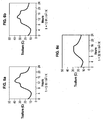
- FIGs 5a to 5d illustrate the results of a theoretical calculation of the heating of the culture in the reaction chamber during a standard day when the photobioreactor 1 does not include a thermal valve 13 ( figure 5a ) or comprises a thermal valve 13 of phase change material having a thickness of 1 cm ( figure 5b ), 2 cm ( figure 5c ) and 3 cm ( figure 5d ).
- the temperature within the reaction chamber also reaches a maximum of 40 ° C around 13:00 and remains above 30 ° C for four hours, three hours less than in the case illustrated on the figure 5a .
- the temperature within the reaction chamber remains below 35 ° C throughout the day and above 30 ° C for about two hours and twenty minutes, or nearly four hours and forty minutes less than in the case illustrated on the figure 5a .
- the temperature peak is shifted to around 14:45.
- FIGS. 6a to 6c illustrate the heating of the culture within the reaction chamber during a standard day when the photobioreactor 1 comprises a glass filter, a thermal valve 13 of phase change material having a thickness of 1 cm without a heat exchanger ( figure 6a ): and with a heat exchanger developing an enlarged surface (comprising fins) making it possible to increase the initial exchange surface (here 0.7 m 2 ) by a factor of 2 ( figure 6b ) or by a factor of 6 ( Figure 6c ).
- the calculations presented here for illustrative purposes were carried out in the case of an exchange under natural convection conditions leading to an exchange coefficient of 5 W ⁇ m -2 ⁇ K -1 ,
- the figure 6a corresponds to the figure 5b . It will not be further commented.
- gas A in particular CO2
- nutrients are made by dedicated ducts known to those skilled in the art, for example at the level of the duct 14.
- withdrawal for harvesting microorganisms is carried out by all appropriate means known to those skilled in the art, for example by means provided for this purpose on the conduit 14, when the conditions are met.
Landscapes
- Life Sciences & Earth Sciences (AREA)
- Chemical & Material Sciences (AREA)
- Health & Medical Sciences (AREA)
- Engineering & Computer Science (AREA)
- Wood Science & Technology (AREA)
- Organic Chemistry (AREA)
- Bioinformatics & Cheminformatics (AREA)
- Zoology (AREA)
- Genetics & Genomics (AREA)
- Biotechnology (AREA)
- Microbiology (AREA)
- Sustainable Development (AREA)
- Biomedical Technology (AREA)
- Biochemistry (AREA)
- General Engineering & Computer Science (AREA)
- General Health & Medical Sciences (AREA)
- Physics & Mathematics (AREA)
- Analytical Chemistry (AREA)
- Thermal Sciences (AREA)
- Molecular Biology (AREA)
- Apparatus Associated With Microorganisms And Enzymes (AREA)
Claims (9)
- Photoreaktor (1), umfassend eine abgeschlossene Reaktionskammer (15), wobei die Kammer (15) vom Außenbereich durch eine Wand (11) zur Erfassung von Licht und eine andere Wand (12) getrennt ist, wobei die Wand zur Erfassung und die andere Wand untereinander parallel sind;
der Photoreaktor (1) umfasst außerdem ein thermisches Ventil (13), das gegen die andere Wand (12) angebracht ist, um auf passive Weise die Erhöhung der Wärme im Inneren der Kammer (15) aufgrund der Strahlung, die die Wand (11) zur Erfassung durchdringt, zu steuern, um die Temperatur in mindestens einem Teil der Kammer (15) unter einer Schwellentemperatur (Ts) zu halten, wobei das thermische Ventil (13) aus einem Phasenwechselmaterial zusammengesetzt ist,
dadurch gekennzeichnet, dass der Photoreaktor (1) einen Wärmetauscher (16) umfasst, der gegen das thermische Ventil (13) angebracht ist, gegebenenfalls gegenüber der anderen Wand, und einen Wärmetausch zwischen dem thermischen Ventil (13) und dem Außenbereich sicherstellt. - Photoreaktor (1) nach Anspruch 1, dadurch gekennzeichnet, dass der Reaktor ein Photobioreaktor ist.
- Photoreaktor (1) nach Anspruch 1 oder 2, wobei das Material ein Paraffin ist.
- Photoreaktor (1) nach Anspruch 3, wobei das Material ein Paraffin mit einem Temperaturbereich des Phasenwechsels nahe 30 °C ist.
- Photoreaktor (1) nach Anspruch 1 oder 2, wobei das Material ausgewählt ist aus den folgenden Produkten:- Alkanen oder Paraffinen: insbesondere n-Octadecan, Nonadecan,- organischen Materialien außer Paraffin: insbesondere Caprinsäure; 1-Dodecanol, Octadecylthioglycolat; Methylpalmitat, Methylstearat, Ethylstearat, und einer Mischung dieser drei Bestandteile; Milchsäure; Vinylstearat;- anorganischen Materialien, insbesondere hexahydriertem Calciumchlorid; hexahydriertem Mangannitrat; trihydriertem Lithiumnitrat; decahydriertem Natriumsulfat;- anorganischem Eutektika; insbesondere Calciumchlorid mit hexahydriertem Magnesiumchlorid; tetrahydriertem Calciumnitrat mit hexahydriertem Zinknitrat; Calcium- Natrium- und Kaliumchlorid mit Wasser; decahydriertem Natriumsulfat mit Wasser.
- Photoreaktor nach einem der Ansprüche 1 bis 5, wobei die Wand (11) zur Erfassung und die andere Wand (12) eben und geneigt mit Bezug auf den Boden sind, wodurch ein Abfluss sichergestellt wird, wobei die Wand (11) zur Erfassung über der anderen Wand (12) angeordnet ist.
- Photoreaktor (1) nach einem der Ansprüche 1 bis 6, außerdem umfassend ein Mittel, das einen Filter bildet, der nur die nützlichen Strahlen passieren lässt.
- Photoreaktor nach einem der Ansprüche 1 bis 7, wobei der Wärmetauscher (16) ein Rippenkühler ist.
- Photoreaktor nach einem der Ansprüche 1 bis 8, wobei das thermische Ventil (13) nachgelagert vom Abfluss angeordnet ist und außerdem einen Abflussregler (17) umfasst, um die Schleife (14) des Abflusses der Flüssigkeit im Inneren der Reaktionskammer (15) zu trennen, wenn die Temperatur in der Reaktionskammer (15) eine andere Temperaturschwelle (Ts') übersteigt, wobei sich die Flüssigkeit nachgeordnet vom Abfluss ansammelt.
Applications Claiming Priority (2)
| Application Number | Priority Date | Filing Date | Title |
|---|---|---|---|
| FR1057285A FR2964666B1 (fr) | 2010-09-13 | 2010-09-13 | Dispositif de controle de la temperature d'un photobioreacteur solaire a eclairage direct |
| PCT/EP2011/065874 WO2012035027A1 (fr) | 2010-09-13 | 2011-09-13 | Dispositif de controle de la temperature d'un photobioreacteur solaire a eclairage direct |
Publications (2)
| Publication Number | Publication Date |
|---|---|
| EP2616534A1 EP2616534A1 (de) | 2013-07-24 |
| EP2616534B1 true EP2616534B1 (de) | 2016-01-20 |
Family
ID=44023036
Family Applications (1)
| Application Number | Title | Priority Date | Filing Date |
|---|---|---|---|
| EP11757846.8A Active EP2616534B1 (de) | 2010-09-13 | 2011-09-13 | Vorrichtung zur temperaturregelung eines sonnenphotobioreaktors mit direktbeleuchtung |
Country Status (6)
| Country | Link |
|---|---|
| US (1) | US20130177975A1 (de) |
| EP (1) | EP2616534B1 (de) |
| JP (1) | JP5894994B2 (de) |
| ES (1) | ES2568622T3 (de) |
| FR (1) | FR2964666B1 (de) |
| WO (1) | WO2012035027A1 (de) |
Families Citing this family (5)
| Publication number | Priority date | Publication date | Assignee | Title |
|---|---|---|---|---|
| KR101608214B1 (ko) | 2014-06-24 | 2016-04-04 | 한국에너지기술연구원 | 온도조절이 가능한 광생물 반응장치 |
| FR3089521A1 (fr) | 2018-12-10 | 2020-06-12 | Commissariat A L'energie Atomique Et Aux Energies Alternatives | photobioréacteur |
| KR102787291B1 (ko) | 2019-01-15 | 2025-03-27 | 사빅 글로벌 테크놀러지스 비.브이. | 화학 물질의 생성에서 간헐적 에너지의 사용 |
| US20210371800A1 (en) * | 2020-06-01 | 2021-12-02 | Exxonmobil Research And Engineering Company | Systems and methods for thermal management of algae cultivation systems |
| US11508488B2 (en) | 2020-09-10 | 2022-11-22 | Battelle Energy Alliance, Llc | Heat transfer systems for nuclear reactor cores, and related systems |
Family Cites Families (24)
| Publication number | Priority date | Publication date | Assignee | Title |
|---|---|---|---|---|
| FR956870A (de) | 1950-02-09 | |||
| US2646972A (en) * | 1950-02-04 | 1953-07-28 | Knapp Monarch Co | Fin type radiator |
| SE422872B (sv) | 1977-07-07 | 1982-04-05 | Heden Carl Goeran | Sett och anordning for att klimatisera en byggnadskonstruktion |
| NL9100715A (nl) * | 1991-04-25 | 1992-11-16 | Bopam B V I O | Reactor voor het kweken van algen. |
| GB9309429D0 (en) * | 1993-05-07 | 1993-06-23 | Bioscot Ltd | Fermenter accessory |
| AT401476B (de) | 1993-08-20 | 1996-09-25 | Sy Lab Vertriebsges M B H | Thermokammer |
| DE19644992C1 (de) * | 1996-10-30 | 1998-03-12 | Roehm Gmbh | Temperierbares Solarelement für Solarreaktoren |
| FR2823761B1 (fr) | 2001-04-24 | 2003-06-06 | Bertrand Eric Duran | Dispositif permettant la culture industrielle de micro-organismes photosynthetiques flocules (micro-algues) dans le cadre d'exploitation a hauts rendements |
| US20030108976A1 (en) * | 2001-10-09 | 2003-06-12 | Braig James R. | Method and apparatus for improving clinical accuracy of analyte measurements |
| US7294374B2 (en) * | 2003-08-07 | 2007-11-13 | Tcp Reliable, Inc. | Thermal packaging system |
| JP2006204186A (ja) * | 2005-01-28 | 2006-08-10 | Matsushita Electric Ind Co Ltd | 培養装置 |
| EP1928994A2 (de) | 2005-08-25 | 2008-06-11 | Solix Biofuels, Inc. | Verfahren, vorrichtung und system zur biodieselproduktion aus algen |
| US8171984B2 (en) * | 2006-02-01 | 2012-05-08 | Sgl Carbon Ag | Latent heat storage devices |
| WO2007129327A1 (en) | 2006-05-08 | 2007-11-15 | Abhishek Narain Singh | A photo bio-reactor for cultivating and harvesting a bio-mass and a method thereof |
| BRPI0714051A2 (pt) | 2006-07-10 | 2012-12-11 | Greenfuel Technologies Corp | sistema de fotobiorreatores e métodos para tratamento de gás enriquecido com co2 e produção de biomassa |
| US9637714B2 (en) | 2006-12-28 | 2017-05-02 | Colorado State University Research Foundation | Diffuse light extended surface area water-supported photobioreactor |
| WO2008089321A2 (en) | 2007-01-17 | 2008-07-24 | Joe Mccall | Apparatus and methods for production of biodiesel |
| FR2914315B1 (fr) | 2007-03-29 | 2010-08-20 | Chao-Hui Lu | Procedes et systemes pour la photosynthese de microorganismes d'algue |
| WO2009009113A1 (en) * | 2007-07-11 | 2009-01-15 | Program For Appropriate Technology In Health (Path) | Disposable sample processing unit |
| US20090023199A1 (en) * | 2007-07-19 | 2009-01-22 | New England Clean Fuels, Inc. | Micro-organism production system and method |
| JP5033557B2 (ja) * | 2007-09-20 | 2012-09-26 | 株式会社日立製作所 | 温度調整部材 |
| US20090155864A1 (en) * | 2007-12-14 | 2009-06-18 | Alan Joseph Bauer | Systems, methods, and devices for employing solar energy to produce biofuels |
| US20090291490A1 (en) * | 2008-01-18 | 2009-11-26 | Touchstone Research Laboratory, Ltd. | Photo-Bioreactor |
| WO2010011320A1 (en) * | 2008-07-23 | 2010-01-28 | Global Energies, Llc | Bioreactor system for mass production of biomass |
-
2010
- 2010-09-13 FR FR1057285A patent/FR2964666B1/fr active Active
-
2011
- 2011-09-13 WO PCT/EP2011/065874 patent/WO2012035027A1/fr not_active Ceased
- 2011-09-13 ES ES11757846.8T patent/ES2568622T3/es active Active
- 2011-09-13 US US13/822,632 patent/US20130177975A1/en not_active Abandoned
- 2011-09-13 JP JP2013528641A patent/JP5894994B2/ja active Active
- 2011-09-13 EP EP11757846.8A patent/EP2616534B1/de active Active
Also Published As
| Publication number | Publication date |
|---|---|
| WO2012035027A1 (fr) | 2012-03-22 |
| FR2964666A1 (fr) | 2012-03-16 |
| JP5894994B2 (ja) | 2016-03-30 |
| JP2013537042A (ja) | 2013-09-30 |
| FR2964666B1 (fr) | 2014-11-21 |
| EP2616534A1 (de) | 2013-07-24 |
| US20130177975A1 (en) | 2013-07-11 |
| ES2568622T3 (es) | 2016-05-03 |
Similar Documents
| Publication | Publication Date | Title |
|---|---|---|
| EP2616534B1 (de) | Vorrichtung zur temperaturregelung eines sonnenphotobioreaktors mit direktbeleuchtung | |
| US20130145761A1 (en) | Systems and methods for providing supplemental aqueous thermal energy | |
| EP3003984A1 (de) | Wasseraufbereitungsanordnung mit einem solarverdampfer | |
| WO2013011448A1 (fr) | Photo-bioréacteur pour la production d'une solution algale concentrée et dispositif d'exposition de la solution, en particulier pour un tel photo-bioréacteur | |
| FR2957388A1 (fr) | Cheminee solaire de production d'electricite, de recyclage d'eau et de production agricole | |
| US20120184027A1 (en) | Polymer composition for photobioreactors | |
| FR2907311A1 (fr) | Installation d'aquaculture pour micro-algues | |
| WO2017032863A1 (fr) | Dispositif de purification de l'eau | |
| FR2994371A1 (fr) | Dispositif de regulation thermique pour serre agricole | |
| CH701001A2 (fr) | Citerne solaire. | |
| WO2012080198A1 (fr) | Appareil pour la régulation de la température d'un organisme mis en culture | |
| WO2017162254A1 (fr) | Serre maraîchère ou horticole fermée intelligente | |
| FR3129271A1 (fr) | Système passif de régulation thermique passive pour serre agricole | |
| EP4432817A1 (de) | Passives system zur passiven wärmeregulierung für landwirtschaftliches gewächshaus | |
| Tiwari et al. | History of passive solar-distillation systems | |
| WO2013135736A1 (fr) | Dispositif photobioréacteur à énergie positive et procédé mettant en oeuvre un tel photobioréacteur | |
| Aboulfotoh et al. | Solar distillation Systems Design and Enhancements Review | |
| WO2014181047A1 (fr) | Dispositif de capture, d'échange et de stockage thermique de l'énergie solaire | |
| EP0149584A2 (de) | Energiesparender Schirm | |
| WO2014131723A1 (fr) | Agencement pour batiment a isolation thermique adaptative et procede associe | |
| EP3435018B1 (de) | Wärmeenergie-speichervorrichtung, die einen internen tank und ein verteilungssystem eines wärmeübertragungsmittels umfasst | |
| FR2953281A1 (fr) | Capteur solaire simplifie a faible inertie | |
| US20130323713A1 (en) | Sun tracking light distributor system having a v-shaped light distribution channel | |
| FR2993348A1 (fr) | Dispositif d'optimisation des performances d'une pompe a chaleur en periode hivernale, par stockage d'energie en sol profond | |
| FR3008406A1 (fr) | Dispositif de purification d'eau impropre a la consommation par condensation |
Legal Events
| Date | Code | Title | Description |
|---|---|---|---|
| PUAI | Public reference made under article 153(3) epc to a published international application that has entered the european phase |
Free format text: ORIGINAL CODE: 0009012 |
|
| 17P | Request for examination filed |
Effective date: 20130412 |
|
| AK | Designated contracting states |
Kind code of ref document: A1 Designated state(s): AL AT BE BG CH CY CZ DE DK EE ES FI FR GB GR HR HU IE IS IT LI LT LU LV MC MK MT NL NO PL PT RO RS SE SI SK SM TR |
|
| DAX | Request for extension of the european patent (deleted) | ||
| 17Q | First examination report despatched |
Effective date: 20140228 |
|
| REG | Reference to a national code |
Ref country code: DE Ref legal event code: R079 Ref document number: 602011022837 Country of ref document: DE Free format text: PREVIOUS MAIN CLASS: C12M0001000000 Ipc: C12M0001020000 |
|
| GRAP | Despatch of communication of intention to grant a patent |
Free format text: ORIGINAL CODE: EPIDOSNIGR1 |
|
| RIC1 | Information provided on ipc code assigned before grant |
Ipc: C12M 1/02 20060101AFI20150302BHEP Ipc: C12M 1/00 20060101ALI20150302BHEP Ipc: C12M 1/34 20060101ALI20150302BHEP |
|
| INTG | Intention to grant announced |
Effective date: 20150318 |
|
| GRAP | Despatch of communication of intention to grant a patent |
Free format text: ORIGINAL CODE: EPIDOSNIGR1 |
|
| INTG | Intention to grant announced |
Effective date: 20150723 |
|
| GRAS | Grant fee paid |
Free format text: ORIGINAL CODE: EPIDOSNIGR3 |
|
| GRAA | (expected) grant |
Free format text: ORIGINAL CODE: 0009210 |
|
| AK | Designated contracting states |
Kind code of ref document: B1 Designated state(s): AL AT BE BG CH CY CZ DE DK EE ES FI FR GB GR HR HU IE IS IT LI LT LU LV MC MK MT NL NO PL PT RO RS SE SI SK SM TR |
|
| REG | Reference to a national code |
Ref country code: GB Ref legal event code: FG4D Free format text: NOT ENGLISH |
|
| REG | Reference to a national code |
Ref country code: CH Ref legal event code: EP |
|
| REG | Reference to a national code |
Ref country code: IE Ref legal event code: FG4D Free format text: LANGUAGE OF EP DOCUMENT: FRENCH |
|
| REG | Reference to a national code |
Ref country code: AT Ref legal event code: REF Ref document number: 771739 Country of ref document: AT Kind code of ref document: T Effective date: 20160215 |
|
| REG | Reference to a national code |
Ref country code: DE Ref legal event code: R096 Ref document number: 602011022837 Country of ref document: DE |
|
| REG | Reference to a national code |
Ref country code: PT Ref legal event code: SC4A Free format text: AVAILABILITY OF NATIONAL TRANSLATION Effective date: 20160418 |
|
| REG | Reference to a national code |
Ref country code: ES Ref legal event code: FG2A Ref document number: 2568622 Country of ref document: ES Kind code of ref document: T3 Effective date: 20160503 |
|
| REG | Reference to a national code |
Ref country code: NL Ref legal event code: FP |
|
| REG | Reference to a national code |
Ref country code: LT Ref legal event code: MG4D |
|
| REG | Reference to a national code |
Ref country code: AT Ref legal event code: MK05 Ref document number: 771739 Country of ref document: AT Kind code of ref document: T Effective date: 20160120 |
|
| PG25 | Lapsed in a contracting state [announced via postgrant information from national office to epo] |
Ref country code: FI Free format text: LAPSE BECAUSE OF FAILURE TO SUBMIT A TRANSLATION OF THE DESCRIPTION OR TO PAY THE FEE WITHIN THE PRESCRIBED TIME-LIMIT Effective date: 20160120 Ref country code: NO Free format text: LAPSE BECAUSE OF FAILURE TO SUBMIT A TRANSLATION OF THE DESCRIPTION OR TO PAY THE FEE WITHIN THE PRESCRIBED TIME-LIMIT Effective date: 20160420 Ref country code: GR Free format text: LAPSE BECAUSE OF FAILURE TO SUBMIT A TRANSLATION OF THE DESCRIPTION OR TO PAY THE FEE WITHIN THE PRESCRIBED TIME-LIMIT Effective date: 20160421 Ref country code: HR Free format text: LAPSE BECAUSE OF FAILURE TO SUBMIT A TRANSLATION OF THE DESCRIPTION OR TO PAY THE FEE WITHIN THE PRESCRIBED TIME-LIMIT Effective date: 20160120 |
|
| REG | Reference to a national code |
Ref country code: FR Ref legal event code: PLFP Year of fee payment: 6 |
|
| PG25 | Lapsed in a contracting state [announced via postgrant information from national office to epo] |
Ref country code: IS Free format text: LAPSE BECAUSE OF FAILURE TO SUBMIT A TRANSLATION OF THE DESCRIPTION OR TO PAY THE FEE WITHIN THE PRESCRIBED TIME-LIMIT Effective date: 20160520 Ref country code: RS Free format text: LAPSE BECAUSE OF FAILURE TO SUBMIT A TRANSLATION OF THE DESCRIPTION OR TO PAY THE FEE WITHIN THE PRESCRIBED TIME-LIMIT Effective date: 20160120 Ref country code: LV Free format text: LAPSE BECAUSE OF FAILURE TO SUBMIT A TRANSLATION OF THE DESCRIPTION OR TO PAY THE FEE WITHIN THE PRESCRIBED TIME-LIMIT Effective date: 20160120 Ref country code: SE Free format text: LAPSE BECAUSE OF FAILURE TO SUBMIT A TRANSLATION OF THE DESCRIPTION OR TO PAY THE FEE WITHIN THE PRESCRIBED TIME-LIMIT Effective date: 20160120 Ref country code: AT Free format text: LAPSE BECAUSE OF FAILURE TO SUBMIT A TRANSLATION OF THE DESCRIPTION OR TO PAY THE FEE WITHIN THE PRESCRIBED TIME-LIMIT Effective date: 20160120 Ref country code: LT Free format text: LAPSE BECAUSE OF FAILURE TO SUBMIT A TRANSLATION OF THE DESCRIPTION OR TO PAY THE FEE WITHIN THE PRESCRIBED TIME-LIMIT Effective date: 20160120 Ref country code: PL Free format text: LAPSE BECAUSE OF FAILURE TO SUBMIT A TRANSLATION OF THE DESCRIPTION OR TO PAY THE FEE WITHIN THE PRESCRIBED TIME-LIMIT Effective date: 20160120 |
|
| REG | Reference to a national code |
Ref country code: DE Ref legal event code: R097 Ref document number: 602011022837 Country of ref document: DE |
|
| PG25 | Lapsed in a contracting state [announced via postgrant information from national office to epo] |
Ref country code: EE Free format text: LAPSE BECAUSE OF FAILURE TO SUBMIT A TRANSLATION OF THE DESCRIPTION OR TO PAY THE FEE WITHIN THE PRESCRIBED TIME-LIMIT Effective date: 20160120 Ref country code: DK Free format text: LAPSE BECAUSE OF FAILURE TO SUBMIT A TRANSLATION OF THE DESCRIPTION OR TO PAY THE FEE WITHIN THE PRESCRIBED TIME-LIMIT Effective date: 20160120 |
|
| PLBE | No opposition filed within time limit |
Free format text: ORIGINAL CODE: 0009261 |
|
| STAA | Information on the status of an ep patent application or granted ep patent |
Free format text: STATUS: NO OPPOSITION FILED WITHIN TIME LIMIT |
|
| PG25 | Lapsed in a contracting state [announced via postgrant information from national office to epo] |
Ref country code: SK Free format text: LAPSE BECAUSE OF FAILURE TO SUBMIT A TRANSLATION OF THE DESCRIPTION OR TO PAY THE FEE WITHIN THE PRESCRIBED TIME-LIMIT Effective date: 20160120 Ref country code: RO Free format text: LAPSE BECAUSE OF FAILURE TO SUBMIT A TRANSLATION OF THE DESCRIPTION OR TO PAY THE FEE WITHIN THE PRESCRIBED TIME-LIMIT Effective date: 20160120 Ref country code: SM Free format text: LAPSE BECAUSE OF FAILURE TO SUBMIT A TRANSLATION OF THE DESCRIPTION OR TO PAY THE FEE WITHIN THE PRESCRIBED TIME-LIMIT Effective date: 20160120 Ref country code: CZ Free format text: LAPSE BECAUSE OF FAILURE TO SUBMIT A TRANSLATION OF THE DESCRIPTION OR TO PAY THE FEE WITHIN THE PRESCRIBED TIME-LIMIT Effective date: 20160120 |
|
| 26N | No opposition filed |
Effective date: 20161021 |
|
| PG25 | Lapsed in a contracting state [announced via postgrant information from national office to epo] |
Ref country code: BE Free format text: LAPSE BECAUSE OF NON-PAYMENT OF DUE FEES Effective date: 20160930 Ref country code: BG Free format text: LAPSE BECAUSE OF FAILURE TO SUBMIT A TRANSLATION OF THE DESCRIPTION OR TO PAY THE FEE WITHIN THE PRESCRIBED TIME-LIMIT Effective date: 20160420 Ref country code: SI Free format text: LAPSE BECAUSE OF FAILURE TO SUBMIT A TRANSLATION OF THE DESCRIPTION OR TO PAY THE FEE WITHIN THE PRESCRIBED TIME-LIMIT Effective date: 20160120 |
|
| PG25 | Lapsed in a contracting state [announced via postgrant information from national office to epo] |
Ref country code: MC Free format text: LAPSE BECAUSE OF FAILURE TO SUBMIT A TRANSLATION OF THE DESCRIPTION OR TO PAY THE FEE WITHIN THE PRESCRIBED TIME-LIMIT Effective date: 20160120 |
|
| REG | Reference to a national code |
Ref country code: CH Ref legal event code: PL |
|
| REG | Reference to a national code |
Ref country code: IE Ref legal event code: MM4A |
|
| PG25 | Lapsed in a contracting state [announced via postgrant information from national office to epo] |
Ref country code: LI Free format text: LAPSE BECAUSE OF NON-PAYMENT OF DUE FEES Effective date: 20160930 Ref country code: IE Free format text: LAPSE BECAUSE OF NON-PAYMENT OF DUE FEES Effective date: 20160913 Ref country code: CH Free format text: LAPSE BECAUSE OF NON-PAYMENT OF DUE FEES Effective date: 20160930 |
|
| REG | Reference to a national code |
Ref country code: FR Ref legal event code: PLFP Year of fee payment: 7 |
|
| PG25 | Lapsed in a contracting state [announced via postgrant information from national office to epo] |
Ref country code: LU Free format text: LAPSE BECAUSE OF NON-PAYMENT OF DUE FEES Effective date: 20160913 |
|
| REG | Reference to a national code |
Ref country code: BE Ref legal event code: MM Effective date: 20160930 |
|
| PG25 | Lapsed in a contracting state [announced via postgrant information from national office to epo] |
Ref country code: HU Free format text: LAPSE BECAUSE OF FAILURE TO SUBMIT A TRANSLATION OF THE DESCRIPTION OR TO PAY THE FEE WITHIN THE PRESCRIBED TIME-LIMIT; INVALID AB INITIO Effective date: 20110913 Ref country code: CY Free format text: LAPSE BECAUSE OF FAILURE TO SUBMIT A TRANSLATION OF THE DESCRIPTION OR TO PAY THE FEE WITHIN THE PRESCRIBED TIME-LIMIT Effective date: 20160120 |
|
| PG25 | Lapsed in a contracting state [announced via postgrant information from national office to epo] |
Ref country code: MT Free format text: LAPSE BECAUSE OF FAILURE TO SUBMIT A TRANSLATION OF THE DESCRIPTION OR TO PAY THE FEE WITHIN THE PRESCRIBED TIME-LIMIT Effective date: 20160120 Ref country code: TR Free format text: LAPSE BECAUSE OF FAILURE TO SUBMIT A TRANSLATION OF THE DESCRIPTION OR TO PAY THE FEE WITHIN THE PRESCRIBED TIME-LIMIT Effective date: 20160120 Ref country code: MK Free format text: LAPSE BECAUSE OF FAILURE TO SUBMIT A TRANSLATION OF THE DESCRIPTION OR TO PAY THE FEE WITHIN THE PRESCRIBED TIME-LIMIT Effective date: 20160120 |
|
| REG | Reference to a national code |
Ref country code: FR Ref legal event code: PLFP Year of fee payment: 8 |
|
| PG25 | Lapsed in a contracting state [announced via postgrant information from national office to epo] |
Ref country code: AL Free format text: LAPSE BECAUSE OF FAILURE TO SUBMIT A TRANSLATION OF THE DESCRIPTION OR TO PAY THE FEE WITHIN THE PRESCRIBED TIME-LIMIT Effective date: 20160120 |
|
| PGFP | Annual fee paid to national office [announced via postgrant information from national office to epo] |
Ref country code: PT Payment date: 20250911 Year of fee payment: 15 |
|
| PGFP | Annual fee paid to national office [announced via postgrant information from national office to epo] |
Ref country code: NL Payment date: 20250930 Year of fee payment: 15 |
|
| PGFP | Annual fee paid to national office [announced via postgrant information from national office to epo] |
Ref country code: GB Payment date: 20250929 Year of fee payment: 15 |
|
| PGFP | Annual fee paid to national office [announced via postgrant information from national office to epo] |
Ref country code: FR Payment date: 20250929 Year of fee payment: 15 |
|
| PGFP | Annual fee paid to national office [announced via postgrant information from national office to epo] |
Ref country code: DE Payment date: 20251029 Year of fee payment: 15 |
|
| PGFP | Annual fee paid to national office [announced via postgrant information from national office to epo] |
Ref country code: IT Payment date: 20250929 Year of fee payment: 15 |
|
| PGFP | Annual fee paid to national office [announced via postgrant information from national office to epo] |
Ref country code: ES Payment date: 20251210 Year of fee payment: 15 |