EP2617338A1 - Système automatique de nettoyage de locaux - Google Patents
Système automatique de nettoyage de locaux Download PDFInfo
- Publication number
- EP2617338A1 EP2617338A1 EP11825510.8A EP11825510A EP2617338A1 EP 2617338 A1 EP2617338 A1 EP 2617338A1 EP 11825510 A EP11825510 A EP 11825510A EP 2617338 A1 EP2617338 A1 EP 2617338A1
- Authority
- EP
- European Patent Office
- Prior art keywords
- vacuum cleaner
- parking module
- robotic vacuum
- drive mechanism
- front cover
- Prior art date
- Legal status (The legal status is an assumption and is not a legal conclusion. Google has not performed a legal analysis and makes no representation as to the accuracy of the status listed.)
- Withdrawn
Links
Images
Classifications
-
- A—HUMAN NECESSITIES
- A47—FURNITURE; DOMESTIC ARTICLES OR APPLIANCES; COFFEE MILLS; SPICE MILLS; SUCTION CLEANERS IN GENERAL
- A47L—DOMESTIC WASHING OR CLEANING; SUCTION CLEANERS IN GENERAL
- A47L9/00—Details or accessories of suction cleaners, e.g. mechanical means for controlling the suction or for effecting pulsating action; Storing devices specially adapted to suction cleaners or parts thereof; Carrying-vehicles specially adapted for suction cleaners
- A47L9/009—Carrying-vehicles; Arrangements of trollies or wheels; Means for avoiding mechanical obstacles
-
- A—HUMAN NECESSITIES
- A47—FURNITURE; DOMESTIC ARTICLES OR APPLIANCES; COFFEE MILLS; SPICE MILLS; SUCTION CLEANERS IN GENERAL
- A47L—DOMESTIC WASHING OR CLEANING; SUCTION CLEANERS IN GENERAL
- A47L2201/00—Robotic cleaning machines, i.e. with automatic control of the travelling movement or the cleaning operation
-
- A—HUMAN NECESSITIES
- A47—FURNITURE; DOMESTIC ARTICLES OR APPLIANCES; COFFEE MILLS; SPICE MILLS; SUCTION CLEANERS IN GENERAL
- A47L—DOMESTIC WASHING OR CLEANING; SUCTION CLEANERS IN GENERAL
- A47L2201/00—Robotic cleaning machines, i.e. with automatic control of the travelling movement or the cleaning operation
- A47L2201/02—Docking stations; Docking operations
-
- A—HUMAN NECESSITIES
- A47—FURNITURE; DOMESTIC ARTICLES OR APPLIANCES; COFFEE MILLS; SPICE MILLS; SUCTION CLEANERS IN GENERAL
- A47L—DOMESTIC WASHING OR CLEANING; SUCTION CLEANERS IN GENERAL
- A47L2201/00—Robotic cleaning machines, i.e. with automatic control of the travelling movement or the cleaning operation
- A47L2201/02—Docking stations; Docking operations
- A47L2201/022—Recharging of batteries
Definitions
- the proposed invention relates to automatic systems that perform room cleaning using robotic equipment.
- Patent of the Russian Federation No. 2357644 published on June 10, 2009 describes a robotic cleaning system that is assumed to be the closest prior art.
- the known system comprises a robotic vacuum cleaner that performs cleaning while moving automatically over the target surface and a charging station designed so that it can be connected to the vacuum cleaner to charge its on-board battery.
- the system additionally allows the robotic vacuum cleaner to freely cross thresholds of any height.
- Robotic vacuum cleaners and their charging stations can have different constructions and performance specifications. Charging stations can be stationary or mobile.
- RU Patent No. 2350252 published on March 27, 2009 describes a robotic vacuum cleaner charging method that allows detecting incorrect connection between the contact terminals and the charging terminals and preventing wrong positioning of the robotic vacuum cleaner in relation to the charging device when the vacuum cleaner is charged manually.
- the robotic vacuum cleaner return system includes a self-guidance signal transmitter, a self-guidance signal receiver and a control device.
- the self-guidance signal receiver is installed in the robotic vacuum cleaner and receives at least one signal transmitted by the self-guidance signal transmitter.
- the control device recognizes the signal and directs the robotic vacuum cleaner to the charging device.
- the robotic vacuum cleaner receives an infrared signal transmitted by the charging device, determines its location and docks with the charging device to charge its on-board battery.
- RU Patent No. 2321879 published on April 10, 2008 proposes a mobile cleaning robot capable of image recognition and a robot guidance system including a charging device with a docking guidance image printed on it.
- RU Patent No. 2311868 published on December 10, 2007 describes an automatic room cleaning system.
- the system includes video cameras and a garbage robot.
- the video cameras are installed in the upper corners of the room and are connected wirelessly through a video lock-in unit and the first transceiver with the second transceiver installed on the garbage robot.
- the garbage robot also includes a transceiver antenna, a microprocessor, batteries, chassis motors, a mechanical gripper with motors, and a garbage compartment.
- the video cameras are stationary, with the combined field of view covering the entire surface of the monitored floor, and the number of video cameras is selected so as to ensure full view of the floor surface.
- RU Patent No. 2303387 published on July 27, 2007 describes an automatic cleaning system and a method of returning the cleaning robot to an external charging device.
- the system includes an external charging device with a charging stand and charging terminals, and a number of transmitting parts that send signals of different strength with different codes.
- the cleaning robot includes a battery, terminals for connection to the charging terminals in order to supply electric energy to the battery, a receiving part that receives signals from the transmitting parts, and a control part that controls the robotic cleaner movement using the signals received by the receiving part.
- An automatic room cleaning system with a cleaning robot and a charging station is also known from application US 2009/0049640 published on February 26, 2009 .
- the charging station additionally provides unloading of the garbage from the cleaning robot to a separate container.
- the common features of the known and the provided robotic room cleaning systems are the robotic vacuum cleaner, the charging station and the control system.
- the charging station can serve as a parking module.
- a parking module and an automatic room cleaning system that comprises a robotic vacuum cleaner, a charging station, a control system, and a parking module are provided.
- the parking module comprises a case (body) that can accommodate at least the robotic vacuum cleaner inside, and a front cover with a controlled drive mechanism that opens and closes the said front cover.
- the object (purpose) of the proposed invention is to provide an automatic room cleaning system with a parking module that would ensure efficient use of the interior space, integration with the design of the room, and prevention of unauthorized and undesired contact of children and pets with the complex, expensive robotic equipment.
- a design of a robotic vacuum cleaner parking module that comprises a case capable of accommodating at least the robotic vacuum cleaner, a front cover controlled by a drive mechanism that opens and closes the said front cover, a drive mechanism controller, and a power supply system is provided.
- Such parking module construction is not known from the prior art.
- a design of an automatic room cleaning system with a robotic vacuum cleaner parking module that comprises a robotic vacuum cleaner, a charging station, and a parking module for the robotic vacuum cleaner integrated under a common control system that synchronizes the operation of the main elements is also provided.
- the provided system is distinguished (characterized) in that the parking module has a case enclosing the robotic vacuum cleaner and the charging station and a front cover with a controlled drive mechanism that opens and closes the cover in response to commands sent by the control system.
- the size and materials of the parking module allow integrating it into the base (socle or dado part) of the furniture to preserve the appearance (design) of the room.
- the control of the robotic vacuum cleaner and the drive mechanism (for example, an electromechanical drive) of the parking module front cover is provided by one common control system which makes the proposed system easier to use.
- the control system consists of several elements and integrates all components of the proposed automatic room cleaning system with the parking module into a single circuit. Creation and programming of such a control system is based on the known means and methods and does not present any difficulties.
- the robotic vacuum cleaner and the drive mechanism of the parking module front cover are designed so as to allow combined and/or separate sending of operating commands from the control system.
- the control system provides control the robotic vacuum cleaner and the drive mechanism together and/or separately.
- the drive mechanism receives power from the controller and can be controlled over a wireless (radio) and/or conductive (galvanic) communication channel.
- the control system comprises a programmable module that stores and processes control commands and provides synchronized control of the robotic vacuum cleaner, the charging station and the front cover drive mechanism; the above elements are usually equipped with the appropriate controllers, sensors and transceivers for this purpose.
- the control system comprises modules that send control command signals to the robotic vacuum cleaner, the charging station and the controller of the parking module front cover drive mechanism, and the above devices comprise elements necessary to execute the control system commands.
- the control system comprises at least one wireless (radio) remote control unit that can receive and transmit commands to the operating elements of the proposed automatic room cleaning system.
- control system it is preferable for the control system to be integrated with the charging station and/or the robotic vacuum cleaner; however, it can also be designed as a separate unit.
- the proposed system can additionally include an audio and/or LED module indicating the execution of the operating commands and/or the specified operating modes.
- the provided technical solution involves installation of a parking space for automatic household cleaning systems - robotic vacuum cleaners with wireless control capabilities - primarily in the standard-size base niches of virtually any furniture set (preferably kitchen furniture).
- the provided automatic parking module is an electronic/mechanical equipment that can be integrated into the standard base niches of furniture sets or other specially allocated spaces. It provides unique ergonomic placement and operation of a robotic vacuum cleaner in household conditions while preserving the appearance of the room, which is an important factor for the consumer.
- the robotic vacuum cleaner with the charging station can be a product of any known manufacturer and is not an independent subject of this invention.
- the parking module comprises the following basic modules and units:
- the mains adapter is the standard static power supply unit of the robotic vacuum cleaner.
- the floor-standing charging base is the standard robotic vacuum cleaner navigation and automatic charging device.
- the communication channel is wireless, and the navigation method is infrared.
- the method of contact between the charging station and the parked robotic vacuum cleaner is galvanic.
- the system can receive power from the standard mains adapter.
- the wireless remote control unit is usually the standard device used to activate and control the robotic vacuum cleaner and program the individual weekly cleaning schedule.
- the controller of the parking module front cover drive mechanism can be, for example, a modified standard car alarm unit with a power output for electric lock control and a function that allows programming the duration of the control pulses sent to the locks.
- the electromechanical drive that opens and closes the front cover can be based on the solutions known from the prior art and presents no difficulties.
- the operating principle of the linear electromechanical drive is similar to automatic garage gates operated by a remote control unit.
- the drive controller can be equipped with a secondary power source and/or connected directly to the standard robotic vacuum cleaner power source.
- Wireless keyrings are an additional independent control channel for the drive controller and are necessary to force the opening/closing of the front cover remotely.
- the robotic vacuum cleaner is at the charging base (the front cover is closed)
- the commands from the additional keyrings are blocked. This provides protection from possible electromechanical synchronization faults.
- the electromagnetic compatibility of the wireless keyrings is as per GOST R 50789-95 and GOST R 41.97 ( Russian State Standards).
- the independent wireless drive controller control channel is used in the following situations:
- the galvanic (conductive) channel is always used when the robot is successfully parked at the charging base, and is essentially a channel for transmission of the module front door opening/closing commands over a cable.
- the presence of +12V voltage at the output of the charging base means that the robot is "present” inside the parking module and generates a command to close the door, while 0V means that the robot is "absent" from the charging base and generates a command to open the door.
- the proposed system operates as follows.
- the parking module case is installed in a prepared base niche - for example, of a kitchen furniture set - suitable in terms of the useful volume. For example, this may require cutting an opening in the base of the furniture to provide the necessary clearance on the right and on the left side so that the parking module front cover would open freely and covering the edges of the material with plastic edge trimming caps.
- the mains adapter is connected through a socket on the back wall of the parking module and is installed in the base space of the furniture.
- the presence and lighting of a signal LED on the front cover can serve as a power and mains adapter status indicator.
- the front cover is opened using the wireless control unit or the additional keyring to allow the robot to navigate to and park at the charging base located inside the parking module.
- an infrared channel for the navigation and parking of the robot, since it is the most accurate and noise-resistant communication channel. Since an infrared signal works efficiently only if a direct line of sight is available, it is preferable to provide free space in a 1 m radius in front of the module for the robot to manoeuvre during the parking.
- Standard robotic vacuum cleaner navigation facilities installed in the rooms in accordance with the manufacturer's recommendations should be used to ensure successful parking of the robot from a room adjacent to the one in which the base is located.
- the robotic vacuum cleaner, the charging station, the parking module and the control system need to be synchronized with each other before the vacuum cleaner can be activated remotely.
- the parking command can be sent from the standard control unit or directly from the robotic vacuum cleaner keyboard.
- the robotic vacuum cleaner receives and processes signals from movement coordinators (if they are available and activated) and the floor-standing charging base, and adjusts its movement path optically to ensure accurate docking with the parking module. Successful parking of the robot at the charging station can be confirmed by audible and light signals.
- the parking module front cover closes automatically in a smooth motion, ensuring concealed ergonomic storage and continuously monitored charging of the robotic vacuum cleaner.
- the robotic vacuum cleaner leaves the parking module when it receives a command from the built-in timer (according to a pre-programmed cleaning schedule) or from a wireless control unit.
- the robotic vacuum cleaner's exit from the parking module is preceded by the synchronous opening of the front door and can be accompanied with an audible and a light signal (such as a melody).
- the robotic vacuum cleaner automatically returns to the charging base in the parking module without human interference, and the door is automatically closed behind it, preventing unauthorized contact with the equipment.
- the owner of such an automatic house cleaning system only needs to periodically empty the dust container and clean the brushes from hairs and garbage.
- the dust container can also be emptied automatically; in this case the user is only required to perform regular servicing of the system.
- the robotic vacuum cleaner cleans the entire visible area of the apartment since there is no blind zone around the charging device.
- the robotic vacuum cleaner occupies no space in the visible area (which is important for small apartments) and does not disrupt the stylistic interior solution.
- the procedure of synchronization between the robotic vacuum cleaner and the parking module consists of several simple operations and is performed when the parking module is installed, for example, in a furniture set. This procedure may need to be repeated in the process of system operation in case of abnormal situations related to power failures, robotic vacuum cleaner faults, or replacement of the remote control unit batteries.
- the synchronization can be automatic (programmed) or semiautomatic (requiring the user to input the necessary commands).
- an individual weekly cleaning schedule can be programmed so that the vacuum cleaner will perform the cleaning when it is convenient for the user.
- the proposed automatic room cleaning system with the robotic vacuum cleaner parking module has definite advantages over similar systems existing in the world.
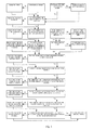
- Fig. 1 shows the logic of the system operation.
- the proposed design of the parking module front door drive that makes use of a linear electric actuator is characterized by simplicity, reliability and precise command execution. However, its relatively high cost and substantial noise produced during the operation can be viewed as disadvantages.
- This technical solution is characterized by a relatively low cost, but allows implementing only one automatic operation - smooth opening of the module front cover.
- the cover is closed manually in this case, which does not meet all the objectives. Therefore, the front cover drive option with a linear electric actuator selected by the developer is the optimum solution that meets all the objectives and ensures that all operations are performed reliably.
- the provided parking module and its design improve the ergonomics of the automatic room cleaning system, save the interior space in the room while preserving its appearance, and prevent undesirable contact of children and pets with the complex, expensive robotic equipment.
Landscapes
- Engineering & Computer Science (AREA)
- Mechanical Engineering (AREA)
- Electric Vacuum Cleaner (AREA)
- Control Of Position, Course, Altitude, Or Attitude Of Moving Bodies (AREA)
Applications Claiming Priority (3)
| Application Number | Priority Date | Filing Date | Title |
|---|---|---|---|
| RU2010138047/12A RU2430672C1 (ru) | 2010-09-14 | 2010-09-14 | Автоматическая система уборки помещения с парковочным модулем для робота-пылесоса |
| RU2010138171 | 2010-09-15 | ||
| PCT/RU2011/000382 WO2012036586A1 (fr) | 2010-09-14 | 2011-06-02 | Système automatique de nettoyage de locaux |
Publications (2)
| Publication Number | Publication Date |
|---|---|
| EP2617338A1 true EP2617338A1 (fr) | 2013-07-24 |
| EP2617338A4 EP2617338A4 (fr) | 2014-08-20 |
Family
ID=45831819
Family Applications (1)
| Application Number | Title | Priority Date | Filing Date |
|---|---|---|---|
| EP11825510.8A Withdrawn EP2617338A4 (fr) | 2010-09-14 | 2011-06-02 | Système automatique de nettoyage de locaux |
Country Status (2)
| Country | Link |
|---|---|
| EP (1) | EP2617338A4 (fr) |
| WO (1) | WO2012036586A1 (fr) |
Cited By (1)
| Publication number | Priority date | Publication date | Assignee | Title |
|---|---|---|---|---|
| DE102014111868A1 (de) * | 2014-08-20 | 2016-02-25 | Miele & Cie. Kg | Ortsfeste Basisstation für einen Saugroboter |
Families Citing this family (1)
| Publication number | Priority date | Publication date | Assignee | Title |
|---|---|---|---|---|
| CN110554653B (zh) * | 2018-05-31 | 2024-08-09 | 中瑞福宁机器人(沈阳)有限公司 | 基于工业控制器和人机界面的集装箱自动清洗的控制系统 |
Family Cites Families (19)
| Publication number | Priority date | Publication date | Assignee | Title |
|---|---|---|---|---|
| SU698076A1 (ru) * | 1976-06-07 | 1979-11-15 | Предприятие П/Я Г-4173 | Электромеханический привод линейных перемещений |
| US5377106A (en) * | 1987-03-24 | 1994-12-27 | Fraunhofer Gesellschaft Zur Foerderung Der Angewandten Forschung E.V. | Process for navigating an unmanned vehicle and a vehicle for the same |
| GB9811241D0 (en) * | 1998-05-27 | 1998-07-22 | Univ Sheffield | Improvements in or relating to cabinets |
| RU18416U1 (ru) * | 2001-02-19 | 2001-06-20 | Подымов Олег Владимирович | Гаражные ворота |
| DE10231388A1 (de) * | 2002-07-08 | 2004-02-05 | Alfred Kärcher Gmbh & Co. Kg | Bodenbearbeitungssystem |
| US7332890B2 (en) | 2004-01-21 | 2008-02-19 | Irobot Corporation | Autonomous robot auto-docking and energy management systems and methods |
| KR100548895B1 (ko) | 2004-05-17 | 2006-02-02 | 삼성광주전자 주식회사 | 로봇 진공청소기의 충전장치 |
| KR100656701B1 (ko) | 2004-10-27 | 2006-12-13 | 삼성광주전자 주식회사 | 로봇청소기 시스템 및 외부충전장치 복귀 방법 |
| KR100766434B1 (ko) | 2005-07-22 | 2007-10-15 | 엘지전자 주식회사 | 영상 인식이 가능한 이동체와 이동체 유도 방법 |
| KR100645381B1 (ko) | 2005-08-31 | 2006-11-14 | 삼성광주전자 주식회사 | 로봇청소기의 외부충전 복귀장치 및 복귀방법 |
| EP2806326B1 (fr) | 2005-09-02 | 2016-06-29 | Neato Robotics, Inc. | Dispositif robotique multifonction |
| DE202005015610U1 (de) * | 2005-09-30 | 2005-12-15 | Alno Ag | Stauraum |
| KR20070074146A (ko) | 2006-01-06 | 2007-07-12 | 삼성전자주식회사 | 청소기 시스템 |
| EP2027806A1 (fr) | 2006-04-04 | 2009-02-25 | Samsung Electronics Co., Ltd. | Système robot nettoyeur doté d'un robot nettoyeur et d'une station d'accueil |
| RU2311868C1 (ru) | 2006-05-22 | 2007-12-10 | Общество с ограниченной ответственностью ООО "Робопром" | Система автоматизированной уборки помещений |
| KR100758038B1 (ko) | 2006-11-22 | 2007-09-11 | 삼성광주전자 주식회사 | 로봇청소기의 충전방법 |
| KR100815570B1 (ko) | 2006-12-06 | 2008-03-20 | 삼성광주전자 주식회사 | 로봇청소기시스템 및 그 제어방법 |
| KR101330734B1 (ko) | 2007-08-24 | 2013-11-20 | 삼성전자주식회사 | 로봇청소기와 도킹 스테이션을 구비하는 로봇청소기 시스템 |
| BG1353U1 (bg) * | 2010-03-22 | 2010-08-31 | Валентин ГЕОРГИЕВ | Автоматична гаражна врата |
-
2011
- 2011-06-02 WO PCT/RU2011/000382 patent/WO2012036586A1/fr not_active Ceased
- 2011-06-02 EP EP11825510.8A patent/EP2617338A4/fr not_active Withdrawn
Cited By (1)
| Publication number | Priority date | Publication date | Assignee | Title |
|---|---|---|---|---|
| DE102014111868A1 (de) * | 2014-08-20 | 2016-02-25 | Miele & Cie. Kg | Ortsfeste Basisstation für einen Saugroboter |
Also Published As
| Publication number | Publication date |
|---|---|
| WO2012036586A1 (fr) | 2012-03-22 |
| EP2617338A4 (fr) | 2014-08-20 |
Similar Documents
| Publication | Publication Date | Title |
|---|---|---|
| US7397342B2 (en) | Operating system for a motorized barrier operator with a radio frequency energized light kit and/or switch and methods for programming the same | |
| US12516561B2 (en) | Door system with integrated electric devices | |
| EP2971853B1 (fr) | Levage motorisé d'habillage de fenêtre et moteur et fonctionnement du système de commande | |
| CA3210095A1 (fr) | Systeme de porte dote d'un faisceau de cables achemine a l'interieur d'une porte et cadre de porte externe pour connexion avec des dispositifs electriques | |
| US20050195066A1 (en) | Operating system and methods for seeding a random serial number for radio frequency control of a barrier operator's accessories | |
| CN1906373A (zh) | 利用电动壁障的自动关闭功能选择性地遮住多功能壁式控制装置发射器的壁障操作系统 | |
| EP3330468A1 (fr) | Système d'ouverture de porte de garage possédant un assistant automatisé intelligent et son procédé de commande | |
| CA2582753C (fr) | Feu mobile pour operateur de barriere mobile | |
| CA2592836A1 (fr) | Batterie de secours pour dispositif de commande de mouvement de barriere et borne de recharge de batterie pour equipement d'alimentation | |
| EP2617338A1 (fr) | Système automatique de nettoyage de locaux | |
| RU104045U1 (ru) | Парковочный модуль для робота-пылесоса и автоматическая система уборки помещения с парковочным модулем для робота-пылесоса | |
| KR100539311B1 (ko) | 자유 롤러에 의해 구동되는,접촉식 안전센서가 부착된 자동문 | |
| RU2430672C1 (ru) | Автоматическая система уборки помещения с парковочным модулем для робота-пылесоса | |
| US12444979B2 (en) | Door operator system with wireless charging capability | |
| CN221129790U (zh) | 基站及清洁系统 | |
| KR20080067156A (ko) | 자동으로 이동하는 디스펜서를 구비하는 냉장고 | |
| KR20090075556A (ko) | 로봇청소기용 격납고 | |
| JPH11315682A (ja) | 電動シャッター | |
| JPH11315683A (ja) | 無線制御シャッターにおける無線送信機のidコード登録方法および抹消方法 | |
| KR200214415Y1 (ko) | 룸 자동제어 장치에 의한 전력 절약 시스템 | |
| JP2001140539A (ja) | 自動ドア装置 |
Legal Events
| Date | Code | Title | Description |
|---|---|---|---|
| PUAI | Public reference made under article 153(3) epc to a published international application that has entered the european phase |
Free format text: ORIGINAL CODE: 0009012 |
|
| 17P | Request for examination filed |
Effective date: 20130320 |
|
| AK | Designated contracting states |
Kind code of ref document: A1 Designated state(s): AL AT BE BG CH CY CZ DE DK EE ES FI FR GB GR HR HU IE IS IT LI LT LU LV MC MK MT NL NO PL PT RO RS SE SI SK SM TR |
|
| DAX | Request for extension of the european patent (deleted) | ||
| A4 | Supplementary search report drawn up and despatched |
Effective date: 20140721 |
|
| RIC1 | Information provided on ipc code assigned before grant |
Ipc: A47B 95/00 20060101ALI20140715BHEP Ipc: A47L 9/00 20060101AFI20140715BHEP |
|
| STAA | Information on the status of an ep patent application or granted ep patent |
Free format text: STATUS: THE APPLICATION IS DEEMED TO BE WITHDRAWN |
|
| 18D | Application deemed to be withdrawn |
Effective date: 20150429 |