EP2617400A2 - Neues Stützsystem zur Behandlung und Prävention von Venenerkrankungen - Google Patents
Neues Stützsystem zur Behandlung und Prävention von Venenerkrankungen Download PDFInfo
- Publication number
- EP2617400A2 EP2617400A2 EP13156175.5A EP13156175A EP2617400A2 EP 2617400 A2 EP2617400 A2 EP 2617400A2 EP 13156175 A EP13156175 A EP 13156175A EP 2617400 A2 EP2617400 A2 EP 2617400A2
- Authority
- EP
- European Patent Office
- Prior art keywords
- layer
- compression
- newtons
- pressure
- contention
- Prior art date
- Legal status (The legal status is an assumption and is not a legal conclusion. Google has not performed a legal analysis and makes no representation as to the accuracy of the status listed.)
- Withdrawn
Links
Images


Classifications
-
- A—HUMAN NECESSITIES
- A61—MEDICAL OR VETERINARY SCIENCE; HYGIENE
- A61F—FILTERS IMPLANTABLE INTO BLOOD VESSELS; PROSTHESES; DEVICES PROVIDING PATENCY TO, OR PREVENTING COLLAPSING OF, TUBULAR STRUCTURES OF THE BODY, e.g. STENTS; ORTHOPAEDIC, NURSING OR CONTRACEPTIVE DEVICES; FOMENTATION; TREATMENT OR PROTECTION OF EYES OR EARS; BANDAGES, DRESSINGS OR ABSORBENT PADS; FIRST-AID KITS
- A61F13/00—Bandages or dressings; Absorbent pads
- A61F13/06—Bandages or dressings; Absorbent pads specially adapted for feet or legs; Corn-pads; Corn-rings
- A61F13/08—Elastic stockings; for contracting aneurisms
-
- A—HUMAN NECESSITIES
- A61—MEDICAL OR VETERINARY SCIENCE; HYGIENE
- A61F—FILTERS IMPLANTABLE INTO BLOOD VESSELS; PROSTHESES; DEVICES PROVIDING PATENCY TO, OR PREVENTING COLLAPSING OF, TUBULAR STRUCTURES OF THE BODY, e.g. STENTS; ORTHOPAEDIC, NURSING OR CONTRACEPTIVE DEVICES; FOMENTATION; TREATMENT OR PROTECTION OF EYES OR EARS; BANDAGES, DRESSINGS OR ABSORBENT PADS; FIRST-AID KITS
- A61F13/00—Bandages or dressings; Absorbent pads
- A61F13/02—Adhesive bandages or dressings
- A61F13/0273—Adhesive bandages for winding around limb, trunk or head, e.g. cohesive
-
- A—HUMAN NECESSITIES
- A61—MEDICAL OR VETERINARY SCIENCE; HYGIENE
- A61F—FILTERS IMPLANTABLE INTO BLOOD VESSELS; PROSTHESES; DEVICES PROVIDING PATENCY TO, OR PREVENTING COLLAPSING OF, TUBULAR STRUCTURES OF THE BODY, e.g. STENTS; ORTHOPAEDIC, NURSING OR CONTRACEPTIVE DEVICES; FOMENTATION; TREATMENT OR PROTECTION OF EYES OR EARS; BANDAGES, DRESSINGS OR ABSORBENT PADS; FIRST-AID KITS
- A61F13/00—Bandages or dressings; Absorbent pads
- A61F2013/00089—Wound bandages
- A61F2013/00119—Wound bandages elastic
- A61F2013/00123—Wound bandages elastic with elastic indicator
Definitions
- the present invention relates to a new compression system for the treatment and prevention of pathologies of venous origin.
- This two-layer system is easy and quick to install.
- An effective restraint system must meet four main objectives.
- the system must be able to be worn continuously day and night for several days (eg a week).
- the system must be easy and quick to install, and this safely, to avoid the risk of tourniquet if the applied pressure is too high, or inefficient if the pressure or pressure differential is too low.
- each band When applied around a limb such as the leg, each band is stretched and depending on the degree of elongation, it applies on the leg a higher or lower pressure.
- This pressure which is the treatment pressure, depends mainly on two factors, the extensibility of the band and the circumference of the limb to which it is applied.
- the elastic bands of contention are thus rolled up to a given extension around the leg. During the winding of the strip, it proceeds to a more or less total recovery thereof on itself. Very often, this recovery is 50%.
- Manufacturers generally provide tables and ranges of products that, for a given limb diameter, determine the pressure to be applied and select the correct system.
- Compression bands are categorized very vaguely by health professionals into two broad categories.
- These strips are intended to be laid at low elongation (for example often defined as less than 70% to 90%) and exert a low resting pressure and a high working pressure. They therefore have a large pressure amplitude, especially during movement, for example during walking.
- Strips with short elongation have many disadvantages.
- Strips with long elongation are for example marketed by the companies 3M, THUASNE and SMITH and NEPHEW respectively under the names Coheban ® , Biflex ® and Proguide ® .
- Strips with short extension in association with a cotton band are for example marketed by ACTIVA under the name Actico ® .
- Such systems are for example marketed by the companies SMITH AND NEPHEW and URGO Limited respectively under the names Profore ® and K4.
- this system applies a low resting pressure without discomfort, a high working pressure and therefore an effective pressure differential.
- All restraint systems known to date mainly aim, by the action of one or more elastic bands in combination with an absorbent padding, to apply on the leg a target pressure of the order of 30 to 50 mmHg for an ankle average of the order of 23 to 25 cm in circumference, and maintain these pressures over time.
- Laplace's law corresponds to a static mathematical model. Its use to develop or choose an effective compression system therefore does not take into account the dynamic aspects related to the evolution and adaptation of the system according to rapid changes in the circumference of the leg during movements. In vivo pressure measurements performed using pressure sensors arranged under a four-layer compression system have shown that such a system can effectively provide an effective pressure differential during movements. However, we do not really know why and what are the characteristics that make it possible to obtain this result.
- the known compression systems using a wadding in combination with one or more elastic bands do not take into account the friction and compression forces that apply between these different layers, nor the diameter variations that inevitably result from the successive laying of the different layers.
- the patent EP 651 628 describes a monolayer compression system resulting from the combination of a self-adhering elastic band and an absorbent layer to obtain a bandage that allows to apply a permanent compressive force when it is lying down.
- the absorbent layer is intended to protect the wound by absorbing compressive forces and absorbing exudates.
- the wadding covers the entire surface of the self-adhesive elastic band, this system can not stand alone. Similarly, if only a portion of the self-adhering strip is covered by the absorbent layer during the winding of the bandage around the member, it increases the risk of sliding from one layer to the other and therefore evolution of the pressure applied over time during the movements.
- a non-homogeneous coating is the source of significant variations in the applied pressures.
- the object of the present invention is therefore to provide a contention system which makes it possible to overcome the interference of the wadding on the applied pressure, which responds to dynamic stresses and their consequences on the overall efficiency during its use, which is easy to install, comfortable and maintains an effective pressure differential over time.
- the inventors have thus analyzed the properties of the known compression systems, by measuring in particular the pressures at the pose, the pressure differential during the movements, the maximum (work) and minimum (rest) compression pressures and their evolutions over time. .
- the dynamic study of the viscoelastic properties of the bands made it possible to determine a new physical characteristic, the dynamic elasticity coefficient, which is correlated with the pressure differences.
- the compression bands are viscoelastic materials whose technical characteristics result from the choice of their constituents, the threads (denier, nature of the fibers, wrapping), their construction textile (weaving, knitting) and additional treatments applied thereto (vaporisation, incorporation of self-adhering latex, adhesivation, etc.).
- the inventors have studied, for the first time, the evolution of the characteristics of various compression systems and their constituents for a given elongation on the tensile-rupture curve, ie the dynamic evolution of these systems and of their constituents around a point of operation. It is by studying this evolution that the inventors have highlighted, in a completely unexpected and surprising way, a dynamic characteristic (that they called dynamic coefficient of elasticity) and that they discovered that There is a correlation, for a given elastic band, between this characteristic and the differential pressure provided by this band, evaluated in vitro.
- the inventors were able to determine the characteristics that must fill an optimized system in the new form of a bilayer system, as well as each of its layers, to be effective and easy to implement.
- each layer of the bilayer system has a value of remanence to the elongation to which it is applied less than 10%.
- each layer of the bilayer system comprises a calibration means in order to set said layer to the appropriate elongation.
- the present invention covers a contention kit which consists of the bilayer contention system defined above and a calibration system for calibrating at least one of the two compression bands before use.
- the present invention makes it possible, by dispensing with the role of the wadding and by virtue of the choice of the dynamic elastic coefficient of each band and of the compression system as a whole, to make available to the nursing staff an efficient, easy-to-use solution. implemented and comfortable for the patient, to treat all pathologies related to venous insufficiency. Furthermore, by allowing to play mainly on the dynamic elasticity coefficients, and subsidiarily on the remanence of the bands used and on the possibilities of calibration, the present invention offers, for the first time in the state of the art, the possibility to adapt the choice of the two layers constituting the compression system, the duration of treatment, the severity of the pathology, especially in the presence of edema or leg ulcers for example.
- the possibility of distributing the pressure differential on the two belts makes it possible to guarantee the possibility of safely developing restraint systems offering a wide range of pressure differentials. It is generally considered that a differential pressure of between 15 mm and 25 mm of mercury is necessary to restore a correct venous flow. However, depending on the pathology, whether it is a treatment on legs without severe ulcer or a difficult treatment on very damaged legs with edema, this range of values can range from 10 to 35 mm of mercury even 10 to 40 mm of mercury.
- the invention makes it possible, for example, to apply to a healthy leg, a working pressure and a higher pressure differential to the extent that the risks of tourniquet or risks Damage to the leg tissues is lower than with known systems, even more so that the pose is facilitated.
- One of the objectives of the present invention is to provide a compression system for ensuring a pressure differential of preferably between 15 and 25 mm of mercury or between 10 and 35 mm of mercury, or even between 10 and 40 mm of mercury if necessary.
- a restraint system will be used which will have a dynamic elasticity coefficient of between 10 and 35 Newtons / cm and more particularly between 15 and 30 Newtons / cm. In this last range of values, it has been found that a pressure differential is obtained which stabilizes rapidly and evolves little or does not evolve over time.
- the first and second layers of the compression system according to the invention will be formed of strips whose dynamic elasticity coefficient is between 1 and 45 Newtons / cm, preferably between 3 and 30 Newtons / cm and more preferably between 5 and 25 Newtons / cm.
- strips which form the two layers of the compression system in order to facilitate the laying of the strips which form the two layers of the compression system and to obtain a stable pressure differential quickly and over time, strips which also have measured remanence at their elongation at laying less than about 10% and preferably between 4 and 8%.
- Such an embodiment is particularly suitable in the case of pathologies that are usually difficult to treat.
- one or each band forming the restraint system of the present invention will be provided with a calibration means.
- This calibration means may be visual, such as for example a set of pictograms, regularly spaced, printed on the tape or made by means of a calibration system such as a stencil by the nursing staff, to whom gives information on recommended lengthening at laying.
- a calibration system such as a stencil by the nursing staff, to whom gives information on recommended lengthening at laying.
- This type of stencil or the explanations necessary to manufacture it can be incorporated into a kit that includes the two compression bands that form the contention system or an assortment of compression bands which makes it possible to produce different suitable restraint systems.
- the stencil is generally made by means of a cardboard sheet in which has been cut an opening which may have, for example, an ellipsoidal or rectangular shape, making it possible, as understood, to produce a pictogram of the same shape on the strip. .
- the rectangular shape which is easier to cut into a cardboard sheet is preferably used.
- the length and the width of the rectangle are determined mathematically according to the elongation at which the strip is to be laid.
- E is the elongation of the strip at the laying
- L the length of the rectangle which will be parallel to the direction of the weft of the strip (that is to say perpendicular to the direction of the length of the strip)
- the The width of the rectangle will be The 1 + E .
- to calibrate a band that one wants to ask at 55% of elongation one will use a rectangle having 4 cm in length a width of 4 / (1 + 0.55) is 2.58 cm.
- One of the main advantages of the present invention is to allow, insofar as they fall within the range of dynamic elasticity coefficient, a large choice in the bands that can be used to obtain an effective contention system.
- An absorbent elastic band for use as a first layer in the restraint system of the present invention may be manufactured according to techniques well known to those skilled in the art. The production of such products is for example described in the patent EP 651 628 in which a self-adhering elastic band is associated with an absorbent layer.
- the elastic band is necessarily self-adhering. It may not be, or even only on one side, for example that opposite to the absorbent layer.
- the absorbent layer may be fixed by any known means on the elastic band to produce the first layer of the contention system according to the invention. However, it must cover the entire surface of the elastic band.
- an absorbent layer consisting of a cotton wool and fix it to the elastic band either by needling or using an adhesive.
- This adhesive may, for example, be a latex of the same nature as that used to cohesive elastic bands to make them self-adherent or an acrylic type adhesive.
- absorbent layers that can be used in the context of the invention, mention may be made, for example, of foams, such as foams based on polyurethane or based on olefins, or woven or non-woven textile materials based on synthetic or natural fibers. , such as wadding.
- foams such as foams based on polyurethane or based on olefins, or woven or non-woven textile materials based on synthetic or natural fibers. , such as wadding.
- textile materials in general have a greater water vapor permeability than foams for equivalent thicknesses.
- these wadding may be made of viscose fibers, polyester, polyurethane, cotton, rayon, etc.
- Such wadding are for example the products marketed by the companies Urgo Limited, Activa or Smith and Nephew respectively under the names K-SOFT ®, BAN ® and FLEXI-SOFT-BAN ®.
- K-SOFT ® wadding which consists of a mixture of 60% viscose fibers and 40% polyester fibers.
- the absorbent layer may optionally contain active agents that contribute to improving the healing of leg ulcers or that can reduce pain or edema, or antibacterial agents.
- antibacterial fibers for example silver fibers
- an antibacterial agent for example triclosan
- an antibacterial agent such as for example a silver-based compound, on the surface of the absorbent layer or on the whole of the first layer of the system (absorbent layer-elastic band ).
- Any type of elastic band may be used for the manufacture of the first layer of the compression system according to the invention, whether it is woven, non-woven or knitted. However, a fabric will be preferred.
- the elastic-absorbing layer-forming layer forming the first layer must have the essential characteristic that makes it possible to obtain an effective compression system, namely a dynamic elasticity coefficient of between 1 and 45 Newtons / cm.
- this first layer provides no pressure or differential value. It then confers on the system a behavior equivalent to that of a wadding.
- the second layer of the compression system according to the invention consists of a self-adhering elastic band which has a dynamic elasticity coefficient of between 1 and 45 Newtons / cm.
- a self-adhering elastic band that can be used as a second layer can be of varied nature.
- elastic bands will be used which are coated with natural rubber latex or with adhesives having a low tack.
- the latex is preferably deposited on both sides of the elastic band at about 0.01 to 75% by weight to provide an elastic band which is adherent to itself without adhering to the skin or clothing.
- latex coatings of the order of 25 to 33 g / m 2 will be preferred.
- Adherent self elastic tapes sold for example by 3M company, ACTIVA, URGO Limited and Smith and Nephew under the respective COHEBAN denominations ®, Actico ®, KO-FLEX ® and PROFORE 4 ® can also be used in the context of the present invention.
- a succession of cycles is applied, which consists of varying the circumference of the cylindrical device at a parameterizable amplitude and speed.
- the variation of circumference is controlled by a pneumatic system.
- the frequency of the cycles is related to the parametrization of the pneumatic system.
- the level of variation of circumference chosen is of the order of 3%, which corresponds to the average deformation value of the circumference of the muscle of the leg when it contracts.
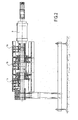
- a series of three strain gage sensors (1a, 1b, 1c) is attached to the device and measures the pressures in real time. All of these data is transmitted via acquisition software to a computer where further processing can be performed.
- the device is generally made of four identical steel plates, smooth, bent and written in a cylinder. These four plates are integral with two conical bearing systems, one of which is fixed and the other can be moved in translation under the action of a cylinder (2) actuated by a pneumatic system.
- the two conical bearing systems return a translation movement which allows the four plates to deviate from the axis by a proportional distance, this distance being adjusted by a fixed control at the end of the jack .
- the electronic sensors are packaged and connected to a three-way datalogger developed by the company DOERLER with an analog digital converter which is in communication via software with a computer for monitoring in time and data processing.
- This cylinder has a minimum perimeter of 35.9 cm and a maximum perimeter of 37 cm which corresponds to the average deformation of 3% chosen to correspond to the average variation of the circumference of the leg between rest and work and during walking .
- t 0 the band at 75% of this deformation, or on a cylinder which has a circumference of 36.2 cm.
- the system is calibrated by static calibration of the sensors using a rigid band to which two weights have been suspended. To carry out the measurements, the systems and the compression bands are wrapped around this cylinder with a single overlap of 100% for the tests carried out below.
- a strip length is cut to obtain this overlap.
- the latter is attached to the desired elongation with the aid of an adhesive tape.
- Laying the desired elongation can also be facilitated by the presence of a calibration means in the form of pictograms on the tape.
- the apparatus has four graduated markings spaced at a distance d 1 equal to the perimeter of the cylinder at installation (36.2 cm) divided by 4 is 9.05 cm.
- the marks d 2 of the template are reported on the band at rest.
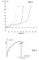
- the dynamic elasticity coefficient is measured according to the following method, the principle of which is illustrated by the figure 3 .
- the test protocol consists of a series of load / discharge traction cycles in the vicinity of a given extension (deformation ⁇ pose ) and of low amplitude (a few percent) around this point (variation: ⁇ max - ⁇ min ) .
- the implementation of the test is performed on a traction machine which is an electronic dynamometer, for example an MTS brand dynamometer, equipped with a 100 Newtons sensor.
- the strip is conditioned at 21 ⁇ 2 ° C and a relative humidity of 60 ⁇ 15% relative humidity for 24 hours.
- the test is performed under the same conditions.
- a strip sample 10 cm wide and 20 cm long is cut to perform the test.
- the strip sample is allowed to rest for 10 minutes before making the measurement.
- the sample is then mounted between the jaws of the electronic dynamometer and then stretched to the extension at laying ( ⁇ pose ) at the speed of 500 mm / min.
- CED F max - F min ⁇ max - ⁇ min 5
- This coefficient is measured at the end of the fifth cycle.
- F max and F min are the forces corresponding to the elongation variations ⁇ max and ⁇ min .
- One of the advantages of this technique is that it also makes it possible to experimentally determine the CED on a pair of bands.
- L 0 represents the initial length of the specimen of a first band intended to be stretched with an elongation rate E 1 .
- L ' 0 represents the length of the specimen of the second band intended to be stretched at a rate of elongation E 2 less than E 1 .
- the 0 The 0 x ⁇ 1 + E 1 1 + E 2 ⁇
- the tensile-elongation test uses the same traction machine (dynamometer of the MTS brand) as previously equipped with a 100 Newtons sensor.
- An elastic band sample 20 cm long and 10 cm wide is subjected to the elongation at which it is desired to measure the force at a speed of 100 mm per minute.
- the test is carried out at a temperature of 21 ⁇ 2 ° C. and a relative humidity of 60 ⁇ 15% relative humidity.
- the desired elongation force is measured on the curve obtained, which is expressed in Newtons per centimeter.
- This test uses the same traction machine under the same conditions as before.
- the strip is subjected to a charge-discharge cycle until the desired elongation of the strip ( ⁇ pose ). At the end of the cycle, the remanence or remanent deformation ⁇ r is thus determined as illustrated in FIG. figure 5 .
- This remanence which is an elongation, is expressed as a percentage.
- the wadding is a nonwoven fabric which is manufactured by the conventional method of carding, topping and pre-needling from viscose fibers and polyester fibers in the proportion 60% -40% by weight.
- This wadding has a basis weight of 75 g per m 2 .
- the same wadding has been used in combination with various elastic bands for the manufacture of the first layers of the restraint system according to the invention.
- Knit 1 Knit 1 :
- Knitting 2
- Knitting 3
- the wadding fabricated previously is unrolled and inserted under the needling machine with one of the knits previously manufactured which is subjected to an extension of the order of 70 to 100%.
- Needling is done with a needle board comprising 15,000 needles for a width of 2.5 to 2.8 meters.
- the wadding-knit that is cut into 10 cm widths that are wound without tension. These widths are then cut to give the elastic bands of desired length which serve as a first layer in the restraint system of the present invention.
- the characteristics of the bands obtained with the knits 1 to 3 are as follows:
- the product After weaving, the product is vaporized until it is completely retracted.
- a latex coating (product sold by SIKA France under the reference SIKACOLL-2057/00) of about 30 g per m 2 of woven product is then produced to give the elastic band its self-adhering character.
- Chain - polyamide thread of 2/78 dtex - Spandex yarn guiped air jet polyamide marketed by the SCHWARZENBACH mills under the reference PE 459SEJ Frames: flesh-colored acrylic thread NM 34/1 Duitage: 10 picks per cm Weight: 175 g / m 2 Strength at 80% elongation: 4.3 Newtons / cm Remanence: 23%
- each of the bands of the contention system is placed at a given extension and it is measured at the laying for each band and each combination the CED in dynamometry and the differential pressure hereinafter ⁇ with the in vitro test apparatus .
- the set of results obtained is collated in Table I below in which the first layer of the contention system according to the invention is referenced under the abbreviation C1 its CED under CED1 and its ⁇ under ⁇ 1 and the second layer under the abbreviation C2 its CED under CED2 and its ⁇ under ⁇ 2.
- the abbreviation CED1 + CED2 represents the sum of the DECs of each band
- the abbreviation ⁇ 1 + ⁇ 2 represents the sum of the differential pressure of each band
- CED (1 + 2) and ⁇ (1 + 2) represents respectively the results of the CED and pressure differential measurements made for all the two layers that form the compression system.
- the percentage of elongation at the pose is specified for each band.
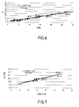
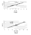
- FIGs 6 to 9 respectively illustrate the correlation curves between ⁇ and CED for the set of individual bands and their associations in the examples of the contention system according to the invention ( figure 6 ), between ⁇ and CED only for the examples of restraint systems according to the invention ( figure 7 ), between the sum of the ⁇ of each individual band and the ⁇ measured for the examples of contention systems according to the invention ( figure 8 ) and between the sum of the CEDs of each band and the measured CEDs for the examples of restraint systems according to the invention ( figure 9 ).
- a compression system consisting of two layers corresponding to Examples 1 and 6 was produced, and CED and ⁇ measurements were made, according to the same methods as previously described for laying methods corresponding to an elongation at 30% of the first. layer (Example 1) and 90% of the second layer (Example 6).
- the figure 10 illustrates the results obtained. It is found that the bilayer system made with the band of Example 6, which is outside the limits set according to the invention in terms of CED, has a continuous decrease in the pressure differential (curve 1). In addition, this pressure differential is very high initially, 52 mm of mercury instead of approximately 35 mm of mercury which is the higher value recommended for efficiency.
- the bilayer system according to the invention (EX2-40% + EX4-50%) has an initial pressure differential value that hardly changes and remains constant over time (curve 3). It is comparable to the result obtained with the PROFORE ® four-layer system (curve 4).
Landscapes
- Health & Medical Sciences (AREA)
- Public Health (AREA)
- Engineering & Computer Science (AREA)
- Heart & Thoracic Surgery (AREA)
- Vascular Medicine (AREA)
- Life Sciences & Earth Sciences (AREA)
- Animal Behavior & Ethology (AREA)
- Biomedical Technology (AREA)
- General Health & Medical Sciences (AREA)
- Veterinary Medicine (AREA)
- Laminated Bodies (AREA)
- Materials For Medical Uses (AREA)
- Orthopedics, Nursing, And Contraception (AREA)
- Percussion Or Vibration Massage (AREA)
- Measuring Pulse, Heart Rate, Blood Pressure Or Blood Flow (AREA)
- Pharmaceuticals Containing Other Organic And Inorganic Compounds (AREA)
- Acyclic And Carbocyclic Compounds In Medicinal Compositions (AREA)
Applications Claiming Priority (2)
| Application Number | Priority Date | Filing Date | Title |
|---|---|---|---|
| FR0651025A FR2898806B1 (fr) | 2006-03-24 | 2006-03-24 | Nouveau systeme de contention pour le traitement et la prevention des pathologies des maladies veineuses |
| EP07731803.8A EP1998730B1 (de) | 2006-03-24 | 2007-03-23 | Neues stützsystem zur behandlung und prävention von venenerkrankungen |
Related Parent Applications (3)
| Application Number | Title | Priority Date | Filing Date |
|---|---|---|---|
| EP07731803.8A Division EP1998730B1 (de) | 2006-03-24 | 2007-03-23 | Neues stützsystem zur behandlung und prävention von venenerkrankungen |
| EP07731803.8A Division-Into EP1998730B1 (de) | 2006-03-24 | 2007-03-23 | Neues stützsystem zur behandlung und prävention von venenerkrankungen |
| EP07731803.8 Division | 2007-03-23 |
Publications (2)
| Publication Number | Publication Date |
|---|---|
| EP2617400A2 true EP2617400A2 (de) | 2013-07-24 |
| EP2617400A3 EP2617400A3 (de) | 2014-12-31 |
Family
ID=37495894
Family Applications (4)
| Application Number | Title | Priority Date | Filing Date |
|---|---|---|---|
| EP13156223.3A Withdrawn EP2818146A1 (de) | 2006-03-24 | 2007-03-23 | Neues Stützsystem zur Behandlung und Prävention von Venenerkrankungen |
| EP13156061.7A Active EP2818145B1 (de) | 2006-03-24 | 2007-03-23 | Neues Stützsystem zur Behandlung und Prävention von Venenerkrankungen |
| EP07731803.8A Active EP1998730B1 (de) | 2006-03-24 | 2007-03-23 | Neues stützsystem zur behandlung und prävention von venenerkrankungen |
| EP13156175.5A Withdrawn EP2617400A3 (de) | 2006-03-24 | 2007-03-23 | Neues Stützsystem zur Behandlung und Prävention von Venenerkrankungen |
Family Applications Before (3)
| Application Number | Title | Priority Date | Filing Date |
|---|---|---|---|
| EP13156223.3A Withdrawn EP2818146A1 (de) | 2006-03-24 | 2007-03-23 | Neues Stützsystem zur Behandlung und Prävention von Venenerkrankungen |
| EP13156061.7A Active EP2818145B1 (de) | 2006-03-24 | 2007-03-23 | Neues Stützsystem zur Behandlung und Prävention von Venenerkrankungen |
| EP07731803.8A Active EP1998730B1 (de) | 2006-03-24 | 2007-03-23 | Neues stützsystem zur behandlung und prävention von venenerkrankungen |
Country Status (9)
| Country | Link |
|---|---|
| US (1) | US7956233B2 (de) |
| EP (4) | EP2818146A1 (de) |
| CN (1) | CN101410074B (de) |
| CA (1) | CA2646799C (de) |
| ES (4) | ES2668851T1 (de) |
| FR (1) | FR2898806B1 (de) |
| PL (2) | PL1998730T3 (de) |
| PT (1) | PT1998730T (de) |
| WO (1) | WO2007113430A1 (de) |
Families Citing this family (13)
| Publication number | Priority date | Publication date | Assignee | Title |
|---|---|---|---|---|
| CN102946835A (zh) * | 2010-05-07 | 2013-02-27 | Iwmt知识产权控股(私人)有限公司 | 组合压迫和吸收敷料/绷带 |
| GB201111059D0 (en) | 2011-06-29 | 2011-08-10 | Lantor Uk Ltd | Compression bandages |
| JP5996248B2 (ja) * | 2012-04-23 | 2016-09-21 | ピップ株式会社 | 身体着用具 |
| EP2875325B1 (de) | 2012-07-19 | 2019-11-13 | 3M Innovative Properties Company | Bestimmung der dehnung einer elastischen bandage |
| FR2994832B1 (fr) | 2012-09-03 | 2014-09-19 | Urgo Lab | Nouvelle bande elastique autoadherente utilisable notamment pour le traitement et la prevention des pathologies d'origine veineuse |
| FR2994833B1 (fr) | 2012-09-03 | 2014-09-19 | Urgo Lab | Nouvelle bande elastique aux proprietes de contention optimisees |
| FR2994834B1 (fr) | 2012-09-03 | 2014-09-19 | Urgo Lab | Nouvelle bande elastique utilisable notamment pour le traitement et la prevention des pathologies d'origine veineuse |
| TWI531358B (zh) * | 2013-10-16 | 2016-05-01 | 國立臺灣大學 | 身體貼附用的貼條 |
| US10791929B2 (en) | 2016-06-06 | 2020-10-06 | Elwha Llc | Systems and methods for monitoring compression with compression bandages having stretchable electronics |
| EP3323394B1 (de) * | 2016-11-21 | 2019-09-18 | 3M Innovative Properties Company | Kompressionshülse |
| FR3066383B1 (fr) | 2017-05-19 | 2020-11-06 | Urgo Rech Innovation Et Developpement | Bande de contention optimisee |
| SE540816C2 (en) * | 2017-07-17 | 2018-11-20 | Ortrud Medical Ab | Tourniquet |
| CN108324430A (zh) * | 2018-01-29 | 2018-07-27 | 海宁市力天袜业有限公司 | 一种用于治疗静脉曲张的医用袜 |
Citations (10)
| Publication number | Priority date | Publication date | Assignee | Title |
|---|---|---|---|---|
| US3613679A (en) | 1969-10-01 | 1971-10-19 | Patricia W Bijou | Elastic bandage with tension indicator |
| US4699133A (en) | 1978-03-28 | 1987-10-13 | Firma Karl Otto Braun Kg | Process for producing a cohesive, self-adhesive, rigid or elastic bandage for fixing, compression and support dressings for medical purposes and bandage produced by this process |
| FR2611756A1 (fr) | 1987-02-17 | 1988-09-09 | Molinier Sa | Procede de fabrication d'une bande de contention cohesive, les moyens de mise en oeuvre et la bande obtenue |
| EP0460040A1 (de) | 1989-02-25 | 1991-12-11 | Smith & Nephew | Gestrickte oder gewirkte elastische bandage. |
| EP0490793A1 (de) | 1990-12-11 | 1992-06-17 | Topic Diffusion Sa | Kompressionsbandage mit Normungsmittel |
| EP0651628A1 (de) | 1992-07-22 | 1995-05-10 | Minnesota Mining & Mfg | Absorbierende selbshaftende elastische bandage. |
| EP0671898A1 (de) | 1992-12-01 | 1995-09-20 | ConvaTec Limited | Bandage |
| EP0820261A1 (de) | 1995-04-01 | 1998-01-28 | Smith & Nephew plc | Mit einem dehnungsindikator versehener artikel aus stoff |
| EP0873097A1 (de) | 1995-11-18 | 1998-10-28 | Bristol-Myers Squibb Company | Verbandssystem |
| EP0876809A1 (de) | 1997-05-08 | 1998-11-11 | Ethicon, Inc. | Bandage mit kompressionsanzeiger |
Family Cites Families (7)
| Publication number | Priority date | Publication date | Assignee | Title |
|---|---|---|---|---|
| DE2515786C3 (de) * | 1975-04-11 | 1979-01-04 | Laerdal, Asmund S., Stavanger (Norwegen) | Druckverband |
| ATE235868T1 (de) * | 1997-05-16 | 2003-04-15 | Ethicon Inc | Mehrschichtige kompressionsbandage |
| US6171985B1 (en) * | 1997-12-01 | 2001-01-09 | 3M Innovative Properties Company | Low trauma adhesive article |
| GB9901085D0 (en) * | 1999-01-20 | 1999-03-10 | Tudorose Decorative Trims Limi | Bandage |
| US7329232B2 (en) * | 2004-02-27 | 2008-02-12 | Circaid Medical Products, Inc. | Limb encircling therapeutic compression device |
| EP1709947A1 (de) * | 2005-04-08 | 2006-10-11 | 3M Innovative Properties Company | Druckbandagensystem |
| CA2784821C (en) * | 2005-06-29 | 2014-01-21 | The Procter & Gamble Company | Disposable absorbent article containing an unapertured skinless elastomeric layer |
-
2006
- 2006-03-24 FR FR0651025A patent/FR2898806B1/fr not_active Expired - Lifetime
-
2007
- 2007-03-23 EP EP13156223.3A patent/EP2818146A1/de not_active Withdrawn
- 2007-03-23 EP EP13156061.7A patent/EP2818145B1/de active Active
- 2007-03-23 US US12/225,263 patent/US7956233B2/en active Active
- 2007-03-23 CN CN2007800104687A patent/CN101410074B/zh active Active
- 2007-03-23 CA CA2646799A patent/CA2646799C/fr active Active
- 2007-03-23 ES ES13156175.5T patent/ES2668851T1/es active Pending
- 2007-03-23 ES ES13156061T patent/ES2668850T3/es active Active
- 2007-03-23 ES ES07731803T patent/ES2668823T3/es active Active
- 2007-03-23 PL PL07731803T patent/PL1998730T3/pl unknown
- 2007-03-23 EP EP07731803.8A patent/EP1998730B1/de active Active
- 2007-03-23 WO PCT/FR2007/050990 patent/WO2007113430A1/fr not_active Ceased
- 2007-03-23 ES ES13156223.3T patent/ES2668869T1/es active Pending
- 2007-03-23 EP EP13156175.5A patent/EP2617400A3/de not_active Withdrawn
- 2007-03-23 PT PT77318038T patent/PT1998730T/pt unknown
- 2007-03-23 PL PL13156061.7T patent/PL2818145T3/pl unknown
Patent Citations (10)
| Publication number | Priority date | Publication date | Assignee | Title |
|---|---|---|---|---|
| US3613679A (en) | 1969-10-01 | 1971-10-19 | Patricia W Bijou | Elastic bandage with tension indicator |
| US4699133A (en) | 1978-03-28 | 1987-10-13 | Firma Karl Otto Braun Kg | Process for producing a cohesive, self-adhesive, rigid or elastic bandage for fixing, compression and support dressings for medical purposes and bandage produced by this process |
| FR2611756A1 (fr) | 1987-02-17 | 1988-09-09 | Molinier Sa | Procede de fabrication d'une bande de contention cohesive, les moyens de mise en oeuvre et la bande obtenue |
| EP0460040A1 (de) | 1989-02-25 | 1991-12-11 | Smith & Nephew | Gestrickte oder gewirkte elastische bandage. |
| EP0490793A1 (de) | 1990-12-11 | 1992-06-17 | Topic Diffusion Sa | Kompressionsbandage mit Normungsmittel |
| EP0651628A1 (de) | 1992-07-22 | 1995-05-10 | Minnesota Mining & Mfg | Absorbierende selbshaftende elastische bandage. |
| EP0671898A1 (de) | 1992-12-01 | 1995-09-20 | ConvaTec Limited | Bandage |
| EP0820261A1 (de) | 1995-04-01 | 1998-01-28 | Smith & Nephew plc | Mit einem dehnungsindikator versehener artikel aus stoff |
| EP0873097A1 (de) | 1995-11-18 | 1998-10-28 | Bristol-Myers Squibb Company | Verbandssystem |
| EP0876809A1 (de) | 1997-05-08 | 1998-11-11 | Ethicon, Inc. | Bandage mit kompressionsanzeiger |
Also Published As
| Publication number | Publication date |
|---|---|
| EP1998730A1 (de) | 2008-12-10 |
| ES2668851T1 (es) | 2018-05-22 |
| CA2646799A1 (fr) | 2007-10-11 |
| ES2668823T1 (es) | 2018-05-22 |
| CN101410074B (zh) | 2013-01-16 |
| US7956233B2 (en) | 2011-06-07 |
| EP2617400A3 (de) | 2014-12-31 |
| PL2818145T3 (pl) | 2024-05-27 |
| PL1998730T3 (pl) | 2019-11-29 |
| ES2668850T3 (es) | 2024-07-24 |
| US20090112145A1 (en) | 2009-04-30 |
| EP2818145B1 (de) | 2024-01-17 |
| EP1998730B1 (de) | 2019-07-03 |
| EP2818146A1 (de) | 2014-12-31 |
| FR2898806B1 (fr) | 2008-07-04 |
| ES2668869T1 (es) | 2018-05-22 |
| ES2668850T1 (es) | 2018-05-22 |
| EP2818145A1 (de) | 2014-12-31 |
| CA2646799C (fr) | 2013-10-29 |
| FR2898806A1 (fr) | 2007-09-28 |
| WO2007113430A1 (fr) | 2007-10-11 |
| CN101410074A (zh) | 2009-04-15 |
| ES2668823T3 (es) | 2020-03-17 |
| PT1998730T (pt) | 2019-10-08 |
Similar Documents
| Publication | Publication Date | Title |
|---|---|---|
| EP1998730B1 (de) | Neues stützsystem zur behandlung und prävention von venenerkrankungen | |
| EP3380660B1 (de) | Optimiertes kompressionsband und anwendungssatz mit diesem band | |
| Krueger et al. | Age‐related changes in skin mechanical properties: a quantitative evaluation of 120 female subjects | |
| FR2942130A1 (fr) | Procede d'evaluation de la tenue sur le membre inferieur d'une orthese de contention veineuse elastique tricotee | |
| EP3625385B1 (de) | Optimierte kompressionsbandage | |
| EP2892483B1 (de) | Neuartige elastische bandage mit verbesserten stützeigenschaften | |
| EP4017447B1 (de) | Kompressionsbandage mit optimierter oberfläche | |
| US9913754B2 (en) | Self-adhesive elastic bandage that can be used, in particular, for the treatment and prevention of diseases of the veins | |
| FR3089405A1 (fr) | Dispositif de retenue et système de contention comprenant un article de contention et un tel dispositif de retenue | |
| WO2014033419A1 (fr) | Nouvelle bande elastique utilisable notamment pour le traitement et la prevention des pathologies d'origine veineuse | |
| EP3890533B1 (de) | Haltevorrichtung sowie rückhaltesystem mit einer rückhaltebekleidung und solch einer haltevorrichtung | |
| EP2294974B1 (de) | Verfahren zur Charakterisierung einer elastischen gestrickten Kompressionsorthese |
Legal Events
| Date | Code | Title | Description |
|---|---|---|---|
| PUAI | Public reference made under article 153(3) epc to a published international application that has entered the european phase |
Free format text: ORIGINAL CODE: 0009012 |
|
| AC | Divisional application: reference to earlier application |
Ref document number: 1998730 Country of ref document: EP Kind code of ref document: P |
|
| AK | Designated contracting states |
Kind code of ref document: A2 Designated state(s): AT BE BG CH CY CZ DE DK EE ES FI FR GB GR HU IE IS IT LI LT LU LV MC MT NL PL PT RO SE SI SK TR |
|
| PUAL | Search report despatched |
Free format text: ORIGINAL CODE: 0009013 |
|
| AK | Designated contracting states |
Kind code of ref document: A3 Designated state(s): AT BE BG CH CY CZ DE DK EE ES FI FR GB GR HU IE IS IT LI LT LU LV MC MT NL PL PT RO SE SI SK TR |
|
| RIC1 | Information provided on ipc code assigned before grant |
Ipc: A61F 13/02 20060101AFI20141125BHEP Ipc: A61F 13/08 20060101ALI20141125BHEP |
|
| 17P | Request for examination filed |
Effective date: 20150624 |
|
| RBV | Designated contracting states (corrected) |
Designated state(s): AT BE BG CH CY CZ DE DK EE ES FI FR GB GR HU IE IS IT LI LT LU LV MC MT NL PL PT RO SE SI SK TR |
|
| RAP1 | Party data changed (applicant data changed or rights of an application transferred) |
Owner name: URGO RECHERCHE INNOVATION ET DEVELOPPEMENT |
|
| STAA | Information on the status of an ep patent application or granted ep patent |
Free format text: STATUS: EXAMINATION IS IN PROGRESS |
|
| 17Q | First examination report despatched |
Effective date: 20180406 |
|
| REG | Reference to a national code |
Ref country code: ES Ref legal event code: GD2A Effective date: 20201124 |
|
| REG | Reference to a national code |
Ref country code: ES Ref legal event code: GD2A Effective date: 20210311 |
|
| P01 | Opt-out of the competence of the unified patent court (upc) registered |
Effective date: 20230512 |
|
| STAA | Information on the status of an ep patent application or granted ep patent |
Free format text: STATUS: THE APPLICATION IS DEEMED TO BE WITHDRAWN |
|
| 18D | Application deemed to be withdrawn |
Effective date: 20240216 |