EP2617525A2 - Einstellbarer Schleifschärfer - Google Patents
Einstellbarer Schleifschärfer Download PDFInfo
- Publication number
- EP2617525A2 EP2617525A2 EP20130151561 EP13151561A EP2617525A2 EP 2617525 A2 EP2617525 A2 EP 2617525A2 EP 20130151561 EP20130151561 EP 20130151561 EP 13151561 A EP13151561 A EP 13151561A EP 2617525 A2 EP2617525 A2 EP 2617525A2
- Authority
- EP
- European Patent Office
- Prior art keywords
- abrasive elements
- slot
- pair
- rod
- adjustable
- Prior art date
- Legal status (The legal status is an assumption and is not a legal conclusion. Google has not performed a legal analysis and makes no representation as to the accuracy of the status listed.)
- Granted
Links
Images



Classifications
-
- B—PERFORMING OPERATIONS; TRANSPORTING
- B24—GRINDING; POLISHING
- B24D—TOOLS FOR GRINDING, BUFFING OR SHARPENING
- B24D15/00—Hand tools or other devices for non-rotary grinding, polishing, or stropping
- B24D15/06—Hand tools or other devices for non-rotary grinding, polishing, or stropping specially designed for sharpening cutting edges
- B24D15/08—Hand tools or other devices for non-rotary grinding, polishing, or stropping specially designed for sharpening cutting edges of knives; of razors
- B24D15/081—Hand tools or other devices for non-rotary grinding, polishing, or stropping specially designed for sharpening cutting edges of knives; of razors with sharpening elements in interengaging or in mutual contact
Definitions
- This invention relates to sharpening knives and the like, and more particularly, to an improved adjustable abrasive sharpener.
- abrasive sharpeners for knives and the like exist having fixed abrasive elements forming a V-shaped sharpening slot.
- Such known fixed abrasive elements are oriented at a fixed angle to sharpen a blade at an angle as desired for a range of different knife types.
- Most sharpeners are set at either a standard angle and/or an Asian angle that is preset and static. All manufacturers use blades that produce set knife angles that may vary from knife style to another. These varying set angles may not match the standard or santoku angle of prior fixed angle sharpeners. Accordingly, it is desirable in the prior art to provide an adjustable V-shaped sharpener by which the sharpening angle may be varied to range of sharpening angles to more closely match the prescribed sharpening angle of the knife edge from the original blade manufacture.
- the sharpener includes a pair of pivotally mounted abrasive elements forming a sharpening slot whereby the abrasive elements can selectively be moved toward and away from each other to vary their orientation and sharpening angle.
- Such adjustability is achieved by a rotary adjustment mechanism for ease of use and significant control of the angle between a respective pair of abrasive elements.
- the adjustable abrasive sharpener of the invention for sharpening knife blades and the like, generally designated by reference numeral 2.
- the sharpener 2 discloses a manual adjustment of the sharpening angle, it is within the scope of the invention to employ other techniques employing the invention, such as an electro-mechanical mechanism (not shown) and the like.
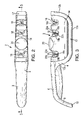
- the abrasive sharpener 2 includes an elongated frame 4 forming a handle portion 6 at one end.
- the end 8 of handle 6 curves downward and includes a flat bottom surface 10 which serves as a support area during sharpening.
- the frame 4 further includes upwardly opening U-shaped section 12 forming a bottom support surface 12a and a curve upward extending portion 12b ( Figs 3 ).
- a housing 14 is positioned within the U-sharped section 12.
- a sharpening slot 16 having abrasive elements 16a which are oriented to each other at a generally fixed V-angle is provided on the top of housing 14.
- a pair of additional slots 18 are formed on the top of housing 14 and each include a pair of pivotally mounted abrasive elements 18a, 18b forming an adjustable generally V-angle to be capable of varying the sharpening angle of the blade of a knife dependent on desired results.
- the abrasive elements 18a, 18b can simultaneously be adjusted toward and away from each other through rotation of exterior adjustment actuator, such as knob 20, which is shown being situated between the two respective slots 18. It is within the scope of the invention, however, to situate the knob 20 on either side of one of the adjustable slots 18 or other desired position where convenient.
- the abrasive elements 18a and 18b in each slot 18 are arranged with respect to each other to form a cutting slot having a generally V-configuration to sharpen an inserted blade edge (not shown) through its movement through the slots 18.
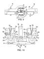
- the abrasive elements 18a are affixed to a removable support 22a mounted on pivotal arm 23a by a threaded member 24a as seen in Figs. 4, 5 , 8 , and 10 .
- the opposing abrasive elements 18b are affixed to a removable support 22b mounted on a removable arm 23b by a threaded member 24b.
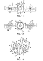
- the pivot arms 22a, 22b of both adjustable slots are pivotally mounted on pivot pin 26. As seen in Figs 7, 8 , and 11 , the arms 23a and 23b are offset from other in a lateral direction relative to the frame 4 and extend downward.
- the hub 20a of the adjustment knob 20 is suitably secured to a downwardly extending rod 28 having a lower open ended reduced end portion 28a and acting as part of the adjustment actuator of the invention.
- a lower elongated pinion 30 is secured end portion 28a ( Figs. 5 , 6 and 8-10 ).
- a spring 32 is disposed between the lower end 30a of pinion 30 and a portion of frame 4 ( Fig. 5 , 8 , 9 and 10 )
- a circular plate 34 having a plurality of open engagement slots 36 arranged on its periphery for an extent of 360° is rigidly mounted on rod 28 ( Figs. 4 , 8 , 9 , and 12 ).
- the rod 28, pinion 30, and plate 34 are mounted on frame 4 to be rotated for a predetermined range and be vertical moved a limited degree through use of knob 20 as will be apparent.
- an angle locking bracket 40 is mounted in fixed relationship on frame 4.
- the angle locking bracket 40 has an upper plate 42 supported on opposed pairs of spaced legs 44 which are interconnected by an opposed based members 46.
- a modified circular opening 48 is formed in plate 42.
- a cut-out area 48a exceeding the radius of opening 48 extends from a stop surface 50 to a second stop surface 52 ( Fig. 11 ) limits the amount of rotation of shaft 28 by knob 20.
- vertical keys 54 exteriorly projecting on rod 28 rotates in cut-out area 48a for maximum angle of rotation as established between stop surfaces 50, 52 ( Fig 11 and 13 ).
- a pair of connecting members 60,62 in the form of adjustment gear racks are mounted by suitable means on frame 4 for relative reciprocal movement in a direction perpendicular to the axis of rotation of rod 28 as seen in Figs 6, 8 , 9, and 10 .
- the rack 60 includes linear rack gear section 64 which engages pinion 30 at all position vertical positions of rod 28.
- the rack 62 includes linear rack gear section 66 and engages pinion 30 at all suitable vertical positions of rod 28.
- the pinion 30 moves the adjustment racks in opposite directions in either direction of rotation of rod 28 when the engagement pins are released.
- the end portions 60a of adjustment racks 60 include a plurality of upwardly opening slots 62a.
- the end portions 62a of adjustment racks 62 include a plurality of upwardly opening slots 62b ( Fig. 5 ).
- the bottom of pivot arm 23b is formed in a curvature from which four projections 70 project into corresponding slots 62a for an extent dependent on the rotational position of the pivot arm 23a as established by the relative position of the adjustment rack 60.
- the bottom of pivot arm 23b is formed with a curvature from which four projections 72 extend into a corresponding slots 62a for an extent on the rotational position of the pivot arm 23b as established by the relative position of the adjustment rack 62.
- knob 20 will move adjustment rack 62 from right to left through pinion 30 to pivot arm 23b toward pivot arm 23a.
- the angle between abrasive elements 18a and 18b in both slots are varied.
- the knob 20 may rotate in a counter clockwise direction viewing Fig.7 .
- the knob 20 must be depressed to release the engagement in order to permit adjustment rotation of the knob 20.
- Indicia elements may be provided exteriorly adjacent the knob 20 to indicate a range of sharpening angles dependent on the extent of rotation of knob 20 and pinion gear 30.
- the knob is released and spring 32 urges automatic upward movement of the rod 28 and circular plate 34 so as the four engagement pins 60 are inserted into four engaging slots 36 which are in alignment with the engagement pins 60 as established by the angular relationship of pivot arms 23a, 23b in a particular adjusted position.
- the abrasive elements 18a, 18b in the two sharpening slots may have different abrasive properties, such as a coarser and finer abrasive quality.
Landscapes
- Engineering & Computer Science (AREA)
- Mechanical Engineering (AREA)
- Finish Polishing, Edge Sharpening, And Grinding By Specific Grinding Devices (AREA)
Applications Claiming Priority (2)
| Application Number | Priority Date | Filing Date | Title |
|---|---|---|---|
| US201261632038P | 2012-01-17 | 2012-01-17 | |
| US13/660,944 US8944894B2 (en) | 2012-10-25 | 2012-10-25 | Adjustable abrasive sharpener |
Publications (3)
| Publication Number | Publication Date |
|---|---|
| EP2617525A2 true EP2617525A2 (de) | 2013-07-24 |
| EP2617525A3 EP2617525A3 (de) | 2014-10-29 |
| EP2617525B1 EP2617525B1 (de) | 2016-11-30 |
Family
ID=47603348
Family Applications (1)
| Application Number | Title | Priority Date | Filing Date |
|---|---|---|---|
| EP13151561.1A Active EP2617525B1 (de) | 2012-01-17 | 2013-01-17 | Einstellbarer Schleifschärfer |
Country Status (1)
| Country | Link |
|---|---|
| EP (1) | EP2617525B1 (de) |
Cited By (3)
| Publication number | Priority date | Publication date | Assignee | Title |
|---|---|---|---|---|
| CN103586788A (zh) * | 2013-11-12 | 2014-02-19 | 无锡万象工业设计有限公司 | 简易磨刀器 |
| CN104511803A (zh) * | 2014-12-18 | 2015-04-15 | 江门市江海区杰能机电科技有限公司 | 一种具有可拆卸防尘罩的磨刀机 |
| USD884450S1 (en) | 2019-03-13 | 2020-05-19 | Mr. Bar-B-Q Products Llc | Knife sharpener |
Families Citing this family (1)
| Publication number | Priority date | Publication date | Assignee | Title |
|---|---|---|---|---|
| CN105904293A (zh) * | 2016-06-06 | 2016-08-31 | 江浩 | 磨刀机 |
Family Cites Families (2)
| Publication number | Priority date | Publication date | Assignee | Title |
|---|---|---|---|---|
| US1909743A (en) * | 1927-03-16 | 1933-05-16 | Blankner William | Knife sharpening device |
| US8727836B2 (en) * | 2010-04-05 | 2014-05-20 | Smith's Consumer Products, Inc. | Electric abrasive sharpener having adjustable abrasive wheels |
-
2013
- 2013-01-17 EP EP13151561.1A patent/EP2617525B1/de active Active
Non-Patent Citations (1)
| Title |
|---|
| None |
Cited By (3)
| Publication number | Priority date | Publication date | Assignee | Title |
|---|---|---|---|---|
| CN103586788A (zh) * | 2013-11-12 | 2014-02-19 | 无锡万象工业设计有限公司 | 简易磨刀器 |
| CN104511803A (zh) * | 2014-12-18 | 2015-04-15 | 江门市江海区杰能机电科技有限公司 | 一种具有可拆卸防尘罩的磨刀机 |
| USD884450S1 (en) | 2019-03-13 | 2020-05-19 | Mr. Bar-B-Q Products Llc | Knife sharpener |
Also Published As
| Publication number | Publication date |
|---|---|
| EP2617525A3 (de) | 2014-10-29 |
| EP2617525B1 (de) | 2016-11-30 |
Similar Documents
| Publication | Publication Date | Title |
|---|---|---|
| US8944894B2 (en) | Adjustable abrasive sharpener | |
| US5431068A (en) | Blade sharpener | |
| EP2617525B1 (de) | Einstellbarer Schleifschärfer | |
| US6261161B1 (en) | Sharpener assembly for a food slicer and related method | |
| US20140342644A1 (en) | Blade Sharpening Stand | |
| US6079924A (en) | Hole-punching and binding apparatus for papers | |
| EP2883655B1 (de) | Einspannmittel für eine Schleifmaschine und Schleifmaschine mit den Einspannmitteln | |
| CN204525056U (zh) | 车削刀具磨刀架 | |
| EP2544856B1 (de) | Messerschärfer für asiatische und europäische/amerikanische messer | |
| CN101678525A (zh) | 用于猎刀和切菜刀的精密刃磨器 | |
| US8092279B2 (en) | Sharpening system for scissors with complex curved blades | |
| CN105980118A (zh) | 斜接角止挡部 | |
| US4241544A (en) | Skate blade sharpener | |
| CA2802382C (en) | Adjustable abrasive sharpener | |
| JP5021355B2 (ja) | 包丁研ぎ器 | |
| CA3112752A1 (en) | Adjustable sharpener | |
| CN203804686U (zh) | 一种斜齿插齿刀具刃磨装置 | |
| EP2723530B1 (de) | Universelle schärfvorrichtung für aufschnittmaschinen mit kreismesser | |
| US2897640A (en) | Portable knife sharpener | |
| CN219504540U (zh) | 磨刀设备和刀具套装 | |
| US1957776A (en) | Sharpener for cutting machines | |
| WO2017029527A1 (en) | A cutting apparatus | |
| RU2828913C1 (ru) | Устройство для заточки ножей | |
| AU2011100677A4 (en) | Sharpening tool | |
| GB2463029A (en) | Knife sharpener and protractor |
Legal Events
| Date | Code | Title | Description |
|---|---|---|---|
| PUAI | Public reference made under article 153(3) epc to a published international application that has entered the european phase |
Free format text: ORIGINAL CODE: 0009012 |
|
| AK | Designated contracting states |
Kind code of ref document: A2 Designated state(s): AL AT BE BG CH CY CZ DE DK EE ES FI FR GB GR HR HU IE IS IT LI LT LU LV MC MK MT NL NO PL PT RO RS SE SI SK SM TR |
|
| AX | Request for extension of the european patent |
Extension state: BA ME |
|
| RIN1 | Information on inventor provided before grant (corrected) |
Inventor name: CHALFANT, LOUIS Inventor name: SMITH, RICHARD S. |
|
| RIN1 | Information on inventor provided before grant (corrected) |
Inventor name: SMITH, RICHARD S. Inventor name: CHALFANT, LOUIS |
|
| PUAL | Search report despatched |
Free format text: ORIGINAL CODE: 0009013 |
|
| AK | Designated contracting states |
Kind code of ref document: A3 Designated state(s): AL AT BE BG CH CY CZ DE DK EE ES FI FR GB GR HR HU IE IS IT LI LT LU LV MC MK MT NL NO PL PT RO RS SE SI SK SM TR |
|
| AX | Request for extension of the european patent |
Extension state: BA ME |
|
| RIC1 | Information provided on ipc code assigned before grant |
Ipc: B24B 3/54 20060101ALI20140922BHEP Ipc: B24B 3/36 20060101ALI20140922BHEP Ipc: B24D 15/08 20060101AFI20140922BHEP |
|
| 17P | Request for examination filed |
Effective date: 20150429 |
|
| RBV | Designated contracting states (corrected) |
Designated state(s): AL AT BE BG CH CY CZ DE DK EE ES FI FR GB GR HR HU IE IS IT LI LT LU LV MC MK MT NL NO PL PT RO RS SE SI SK SM TR |
|
| RIC1 | Information provided on ipc code assigned before grant |
Ipc: B24B 3/36 20060101ALI20160304BHEP Ipc: B24B 3/54 20060101ALI20160304BHEP Ipc: B24D 15/08 20060101AFI20160304BHEP |
|
| GRAP | Despatch of communication of intention to grant a patent |
Free format text: ORIGINAL CODE: EPIDOSNIGR1 |
|
| INTG | Intention to grant announced |
Effective date: 20160607 |
|
| RIN1 | Information on inventor provided before grant (corrected) |
Inventor name: CHALFANT, LOUIS Inventor name: SMITH, RICHARD S. |
|
| GRAS | Grant fee paid |
Free format text: ORIGINAL CODE: EPIDOSNIGR3 |
|
| GRAA | (expected) grant |
Free format text: ORIGINAL CODE: 0009210 |
|
| AK | Designated contracting states |
Kind code of ref document: B1 Designated state(s): AL AT BE BG CH CY CZ DE DK EE ES FI FR GB GR HR HU IE IS IT LI LT LU LV MC MK MT NL NO PL PT RO RS SE SI SK SM TR |
|
| REG | Reference to a national code |
Ref country code: CH Ref legal event code: EP Ref country code: GB Ref legal event code: FG4D |
|
| REG | Reference to a national code |
Ref country code: AT Ref legal event code: REF Ref document number: 849347 Country of ref document: AT Kind code of ref document: T Effective date: 20161215 |
|
| REG | Reference to a national code |
Ref country code: IE Ref legal event code: FG4D |
|
| REG | Reference to a national code |
Ref country code: DE Ref legal event code: R096 Ref document number: 602013014596 Country of ref document: DE |
|
| REG | Reference to a national code |
Ref country code: FR Ref legal event code: PLFP Year of fee payment: 5 |
|
| PG25 | Lapsed in a contracting state [announced via postgrant information from national office to epo] |
Ref country code: LV Free format text: LAPSE BECAUSE OF FAILURE TO SUBMIT A TRANSLATION OF THE DESCRIPTION OR TO PAY THE FEE WITHIN THE PRESCRIBED TIME-LIMIT Effective date: 20161130 |
|
| REG | Reference to a national code |
Ref country code: LT Ref legal event code: MG4D |
|
| REG | Reference to a national code |
Ref country code: NL Ref legal event code: MP Effective date: 20161130 |
|
| REG | Reference to a national code |
Ref country code: AT Ref legal event code: MK05 Ref document number: 849347 Country of ref document: AT Kind code of ref document: T Effective date: 20161130 |
|
| PG25 | Lapsed in a contracting state [announced via postgrant information from national office to epo] |
Ref country code: GR Free format text: LAPSE BECAUSE OF FAILURE TO SUBMIT A TRANSLATION OF THE DESCRIPTION OR TO PAY THE FEE WITHIN THE PRESCRIBED TIME-LIMIT Effective date: 20170301 Ref country code: NO Free format text: LAPSE BECAUSE OF FAILURE TO SUBMIT A TRANSLATION OF THE DESCRIPTION OR TO PAY THE FEE WITHIN THE PRESCRIBED TIME-LIMIT Effective date: 20170228 Ref country code: LT Free format text: LAPSE BECAUSE OF FAILURE TO SUBMIT A TRANSLATION OF THE DESCRIPTION OR TO PAY THE FEE WITHIN THE PRESCRIBED TIME-LIMIT Effective date: 20161130 Ref country code: SE Free format text: LAPSE BECAUSE OF FAILURE TO SUBMIT A TRANSLATION OF THE DESCRIPTION OR TO PAY THE FEE WITHIN THE PRESCRIBED TIME-LIMIT Effective date: 20161130 |
|
| PG25 | Lapsed in a contracting state [announced via postgrant information from national office to epo] |
Ref country code: HR Free format text: LAPSE BECAUSE OF FAILURE TO SUBMIT A TRANSLATION OF THE DESCRIPTION OR TO PAY THE FEE WITHIN THE PRESCRIBED TIME-LIMIT Effective date: 20161130 Ref country code: PT Free format text: LAPSE BECAUSE OF FAILURE TO SUBMIT A TRANSLATION OF THE DESCRIPTION OR TO PAY THE FEE WITHIN THE PRESCRIBED TIME-LIMIT Effective date: 20170330 Ref country code: RS Free format text: LAPSE BECAUSE OF FAILURE TO SUBMIT A TRANSLATION OF THE DESCRIPTION OR TO PAY THE FEE WITHIN THE PRESCRIBED TIME-LIMIT Effective date: 20161130 Ref country code: FI Free format text: LAPSE BECAUSE OF FAILURE TO SUBMIT A TRANSLATION OF THE DESCRIPTION OR TO PAY THE FEE WITHIN THE PRESCRIBED TIME-LIMIT Effective date: 20161130 Ref country code: BE Free format text: LAPSE BECAUSE OF NON-PAYMENT OF DUE FEES Effective date: 20170131 Ref country code: AT Free format text: LAPSE BECAUSE OF FAILURE TO SUBMIT A TRANSLATION OF THE DESCRIPTION OR TO PAY THE FEE WITHIN THE PRESCRIBED TIME-LIMIT Effective date: 20161130 Ref country code: PL Free format text: LAPSE BECAUSE OF FAILURE TO SUBMIT A TRANSLATION OF THE DESCRIPTION OR TO PAY THE FEE WITHIN THE PRESCRIBED TIME-LIMIT Effective date: 20161130 Ref country code: ES Free format text: LAPSE BECAUSE OF FAILURE TO SUBMIT A TRANSLATION OF THE DESCRIPTION OR TO PAY THE FEE WITHIN THE PRESCRIBED TIME-LIMIT Effective date: 20161130 |
|
| PG25 | Lapsed in a contracting state [announced via postgrant information from national office to epo] |
Ref country code: NL Free format text: LAPSE BECAUSE OF FAILURE TO SUBMIT A TRANSLATION OF THE DESCRIPTION OR TO PAY THE FEE WITHIN THE PRESCRIBED TIME-LIMIT Effective date: 20161130 |
|
| PG25 | Lapsed in a contracting state [announced via postgrant information from national office to epo] |
Ref country code: SK Free format text: LAPSE BECAUSE OF FAILURE TO SUBMIT A TRANSLATION OF THE DESCRIPTION OR TO PAY THE FEE WITHIN THE PRESCRIBED TIME-LIMIT Effective date: 20161130 Ref country code: DK Free format text: LAPSE BECAUSE OF FAILURE TO SUBMIT A TRANSLATION OF THE DESCRIPTION OR TO PAY THE FEE WITHIN THE PRESCRIBED TIME-LIMIT Effective date: 20161130 Ref country code: EE Free format text: LAPSE BECAUSE OF FAILURE TO SUBMIT A TRANSLATION OF THE DESCRIPTION OR TO PAY THE FEE WITHIN THE PRESCRIBED TIME-LIMIT Effective date: 20161130 Ref country code: CZ Free format text: LAPSE BECAUSE OF FAILURE TO SUBMIT A TRANSLATION OF THE DESCRIPTION OR TO PAY THE FEE WITHIN THE PRESCRIBED TIME-LIMIT Effective date: 20161130 Ref country code: RO Free format text: LAPSE BECAUSE OF FAILURE TO SUBMIT A TRANSLATION OF THE DESCRIPTION OR TO PAY THE FEE WITHIN THE PRESCRIBED TIME-LIMIT Effective date: 20161130 |
|
| PG25 | Lapsed in a contracting state [announced via postgrant information from national office to epo] |
Ref country code: SM Free format text: LAPSE BECAUSE OF FAILURE TO SUBMIT A TRANSLATION OF THE DESCRIPTION OR TO PAY THE FEE WITHIN THE PRESCRIBED TIME-LIMIT Effective date: 20161130 Ref country code: BG Free format text: LAPSE BECAUSE OF FAILURE TO SUBMIT A TRANSLATION OF THE DESCRIPTION OR TO PAY THE FEE WITHIN THE PRESCRIBED TIME-LIMIT Effective date: 20170228 Ref country code: BE Free format text: LAPSE BECAUSE OF FAILURE TO SUBMIT A TRANSLATION OF THE DESCRIPTION OR TO PAY THE FEE WITHIN THE PRESCRIBED TIME-LIMIT Effective date: 20161130 Ref country code: IT Free format text: LAPSE BECAUSE OF FAILURE TO SUBMIT A TRANSLATION OF THE DESCRIPTION OR TO PAY THE FEE WITHIN THE PRESCRIBED TIME-LIMIT Effective date: 20161130 |
|
| REG | Reference to a national code |
Ref country code: CH Ref legal event code: PL Ref country code: DE Ref legal event code: R097 Ref document number: 602013014596 Country of ref document: DE |
|
| PG25 | Lapsed in a contracting state [announced via postgrant information from national office to epo] |
Ref country code: MC Free format text: LAPSE BECAUSE OF FAILURE TO SUBMIT A TRANSLATION OF THE DESCRIPTION OR TO PAY THE FEE WITHIN THE PRESCRIBED TIME-LIMIT Effective date: 20161130 |
|
| PLBE | No opposition filed within time limit |
Free format text: ORIGINAL CODE: 0009261 |
|
| STAA | Information on the status of an ep patent application or granted ep patent |
Free format text: STATUS: NO OPPOSITION FILED WITHIN TIME LIMIT |
|
| PG25 | Lapsed in a contracting state [announced via postgrant information from national office to epo] |
Ref country code: LI Free format text: LAPSE BECAUSE OF NON-PAYMENT OF DUE FEES Effective date: 20170131 Ref country code: CH Free format text: LAPSE BECAUSE OF NON-PAYMENT OF DUE FEES Effective date: 20170131 |
|
| REG | Reference to a national code |
Ref country code: IE Ref legal event code: MM4A |
|
| 26N | No opposition filed |
Effective date: 20170831 |
|
| PG25 | Lapsed in a contracting state [announced via postgrant information from national office to epo] |
Ref country code: LU Free format text: LAPSE BECAUSE OF NON-PAYMENT OF DUE FEES Effective date: 20170117 Ref country code: SI Free format text: LAPSE BECAUSE OF FAILURE TO SUBMIT A TRANSLATION OF THE DESCRIPTION OR TO PAY THE FEE WITHIN THE PRESCRIBED TIME-LIMIT Effective date: 20161130 |
|
| REG | Reference to a national code |
Ref country code: FR Ref legal event code: PLFP Year of fee payment: 6 |
|
| PG25 | Lapsed in a contracting state [announced via postgrant information from national office to epo] |
Ref country code: IE Free format text: LAPSE BECAUSE OF NON-PAYMENT OF DUE FEES Effective date: 20170117 |
|
| PG25 | Lapsed in a contracting state [announced via postgrant information from national office to epo] |
Ref country code: MT Free format text: LAPSE BECAUSE OF NON-PAYMENT OF DUE FEES Effective date: 20170117 |
|
| PG25 | Lapsed in a contracting state [announced via postgrant information from national office to epo] |
Ref country code: HU Free format text: LAPSE BECAUSE OF FAILURE TO SUBMIT A TRANSLATION OF THE DESCRIPTION OR TO PAY THE FEE WITHIN THE PRESCRIBED TIME-LIMIT; INVALID AB INITIO Effective date: 20130117 |
|
| PG25 | Lapsed in a contracting state [announced via postgrant information from national office to epo] |
Ref country code: CY Free format text: LAPSE BECAUSE OF NON-PAYMENT OF DUE FEES Effective date: 20161130 |
|
| PG25 | Lapsed in a contracting state [announced via postgrant information from national office to epo] |
Ref country code: MK Free format text: LAPSE BECAUSE OF FAILURE TO SUBMIT A TRANSLATION OF THE DESCRIPTION OR TO PAY THE FEE WITHIN THE PRESCRIBED TIME-LIMIT Effective date: 20161130 |
|
| PG25 | Lapsed in a contracting state [announced via postgrant information from national office to epo] |
Ref country code: TR Free format text: LAPSE BECAUSE OF FAILURE TO SUBMIT A TRANSLATION OF THE DESCRIPTION OR TO PAY THE FEE WITHIN THE PRESCRIBED TIME-LIMIT Effective date: 20161130 |
|
| PG25 | Lapsed in a contracting state [announced via postgrant information from national office to epo] |
Ref country code: AL Free format text: LAPSE BECAUSE OF FAILURE TO SUBMIT A TRANSLATION OF THE DESCRIPTION OR TO PAY THE FEE WITHIN THE PRESCRIBED TIME-LIMIT Effective date: 20161130 Ref country code: IS Free format text: LAPSE BECAUSE OF FAILURE TO SUBMIT A TRANSLATION OF THE DESCRIPTION OR TO PAY THE FEE WITHIN THE PRESCRIBED TIME-LIMIT Effective date: 20170330 |
|
| PGFP | Annual fee paid to national office [announced via postgrant information from national office to epo] |
Ref country code: GB Payment date: 20260116 Year of fee payment: 14 |
|
| PGFP | Annual fee paid to national office [announced via postgrant information from national office to epo] |
Ref country code: DE Payment date: 20260118 Year of fee payment: 14 |
|
| PGFP | Annual fee paid to national office [announced via postgrant information from national office to epo] |
Ref country code: FR Payment date: 20260119 Year of fee payment: 14 |