EP2617838B1 - Verfahren zum Betreiben eines Ofens und Ofen - Google Patents
Verfahren zum Betreiben eines Ofens und Ofen Download PDFInfo
- Publication number
- EP2617838B1 EP2617838B1 EP12151907.8A EP12151907A EP2617838B1 EP 2617838 B1 EP2617838 B1 EP 2617838B1 EP 12151907 A EP12151907 A EP 12151907A EP 2617838 B1 EP2617838 B1 EP 2617838B1
- Authority
- EP
- European Patent Office
- Prior art keywords
- furnace
- gas
- thermal treatment
- treatment section
- inert gas
- Prior art date
- Legal status (The legal status is an assumption and is not a legal conclusion. Google has not performed a legal analysis and makes no representation as to the accuracy of the status listed.)
- Not-in-force
Links
- 238000000034 method Methods 0.000 title claims description 29
- 239000007789 gas Substances 0.000 claims description 116
- 238000010438 heat treatment Methods 0.000 claims description 63
- UFHFLCQGNIYNRP-UHFFFAOYSA-N Hydrogen Chemical compound [H][H] UFHFLCQGNIYNRP-UHFFFAOYSA-N 0.000 claims description 39
- 239000001257 hydrogen Substances 0.000 claims description 38
- 229910052739 hydrogen Inorganic materials 0.000 claims description 38
- 239000011261 inert gas Substances 0.000 claims description 28
- 238000005476 soldering Methods 0.000 claims description 24
- URGAHOPLAPQHLN-UHFFFAOYSA-N sodium aluminosilicate Chemical compound [Na+].[Al+3].[O-][Si]([O-])=O.[O-][Si]([O-])=O URGAHOPLAPQHLN-UHFFFAOYSA-N 0.000 claims description 13
- 238000011010 flushing procedure Methods 0.000 claims description 12
- 239000002808 molecular sieve Substances 0.000 claims description 12
- XLYOFNOQVPJJNP-UHFFFAOYSA-N water Substances O XLYOFNOQVPJJNP-UHFFFAOYSA-N 0.000 claims description 9
- 238000005259 measurement Methods 0.000 claims description 6
- 238000001914 filtration Methods 0.000 claims description 4
- 238000000746 purification Methods 0.000 claims description 2
- 238000007669 thermal treatment Methods 0.000 claims 14
- 230000001681 protective effect Effects 0.000 description 32
- 238000010926 purge Methods 0.000 description 30
- 238000005096 rolling process Methods 0.000 description 24
- IJGRMHOSHXDMSA-UHFFFAOYSA-N Atomic nitrogen Chemical compound N#N IJGRMHOSHXDMSA-UHFFFAOYSA-N 0.000 description 20
- 230000008569 process Effects 0.000 description 15
- 229910000679 solder Inorganic materials 0.000 description 14
- QVGXLLKOCUKJST-UHFFFAOYSA-N atomic oxygen Chemical compound [O] QVGXLLKOCUKJST-UHFFFAOYSA-N 0.000 description 11
- 239000000314 lubricant Substances 0.000 description 11
- 238000000926 separation method Methods 0.000 description 11
- 229910052757 nitrogen Inorganic materials 0.000 description 10
- 239000001301 oxygen Substances 0.000 description 10
- 229910052760 oxygen Inorganic materials 0.000 description 10
- 238000005219 brazing Methods 0.000 description 9
- 229910052751 metal Inorganic materials 0.000 description 9
- 239000002184 metal Substances 0.000 description 9
- 230000015572 biosynthetic process Effects 0.000 description 7
- 238000004140 cleaning Methods 0.000 description 7
- 239000000463 material Substances 0.000 description 7
- 238000007789 sealing Methods 0.000 description 7
- 239000003381 stabilizer Substances 0.000 description 7
- 239000000203 mixture Substances 0.000 description 6
- XKRFYHLGVUSROY-UHFFFAOYSA-N Argon Chemical compound [Ar] XKRFYHLGVUSROY-UHFFFAOYSA-N 0.000 description 4
- 238000010494 dissociation reaction Methods 0.000 description 4
- 230000005593 dissociations Effects 0.000 description 4
- 229910044991 metal oxide Inorganic materials 0.000 description 4
- 150000004706 metal oxides Chemical class 0.000 description 4
- 150000002739 metals Chemical class 0.000 description 4
- 239000002245 particle Substances 0.000 description 4
- 239000011148 porous material Substances 0.000 description 4
- 238000005245 sintering Methods 0.000 description 4
- 229910001220 stainless steel Inorganic materials 0.000 description 4
- 238000003860 storage Methods 0.000 description 4
- 239000010457 zeolite Substances 0.000 description 4
- 230000008901 benefit Effects 0.000 description 3
- 239000000919 ceramic Substances 0.000 description 3
- 230000007423 decrease Effects 0.000 description 3
- 230000001419 dependent effect Effects 0.000 description 3
- 238000010586 diagram Methods 0.000 description 3
- 239000002360 explosive Substances 0.000 description 3
- 238000009413 insulation Methods 0.000 description 3
- 239000010935 stainless steel Substances 0.000 description 3
- PXHVJJICTQNCMI-UHFFFAOYSA-N Nickel Chemical compound [Ni] PXHVJJICTQNCMI-UHFFFAOYSA-N 0.000 description 2
- 229910052782 aluminium Inorganic materials 0.000 description 2
- XAGFODPZIPBFFR-UHFFFAOYSA-N aluminium Chemical compound [Al] XAGFODPZIPBFFR-UHFFFAOYSA-N 0.000 description 2
- 229910000323 aluminium silicate Inorganic materials 0.000 description 2
- 229910052786 argon Inorganic materials 0.000 description 2
- 230000004888 barrier function Effects 0.000 description 2
- 230000007797 corrosion Effects 0.000 description 2
- 238000005260 corrosion Methods 0.000 description 2
- 238000011161 development Methods 0.000 description 2
- 230000018109 developmental process Effects 0.000 description 2
- 238000009792 diffusion process Methods 0.000 description 2
- 238000005516 engineering process Methods 0.000 description 2
- 238000004880 explosion Methods 0.000 description 2
- 230000004907 flux Effects 0.000 description 2
- 238000009434 installation Methods 0.000 description 2
- 238000004519 manufacturing process Methods 0.000 description 2
- 239000000155 melt Substances 0.000 description 2
- 230000007935 neutral effect Effects 0.000 description 2
- 230000003647 oxidation Effects 0.000 description 2
- 238000007254 oxidation reaction Methods 0.000 description 2
- 235000011837 pasties Nutrition 0.000 description 2
- 230000006641 stabilisation Effects 0.000 description 2
- 238000011105 stabilization Methods 0.000 description 2
- 241001059810 Cantharellula umbonata Species 0.000 description 1
- VYZAMTAEIAYCRO-UHFFFAOYSA-N Chromium Chemical compound [Cr] VYZAMTAEIAYCRO-UHFFFAOYSA-N 0.000 description 1
- RYGMFSIKBFXOCR-UHFFFAOYSA-N Copper Chemical compound [Cu] RYGMFSIKBFXOCR-UHFFFAOYSA-N 0.000 description 1
- 229910000831 Steel Inorganic materials 0.000 description 1
- 230000000712 assembly Effects 0.000 description 1
- 238000000429 assembly Methods 0.000 description 1
- 230000033228 biological regulation Effects 0.000 description 1
- 239000003638 chemical reducing agent Substances 0.000 description 1
- 229910052804 chromium Inorganic materials 0.000 description 1
- 239000011651 chromium Substances 0.000 description 1
- 230000001143 conditioned effect Effects 0.000 description 1
- 238000010276 construction Methods 0.000 description 1
- 238000004320 controlled atmosphere Methods 0.000 description 1
- 229910052802 copper Inorganic materials 0.000 description 1
- 239000010949 copper Substances 0.000 description 1
- 238000013461 design Methods 0.000 description 1
- 239000000428 dust Substances 0.000 description 1
- 239000003792 electrolyte Substances 0.000 description 1
- 230000007613 environmental effect Effects 0.000 description 1
- 238000000605 extraction Methods 0.000 description 1
- -1 for example Substances 0.000 description 1
- 239000004519 grease Substances 0.000 description 1
- 150000002431 hydrogen Chemical class 0.000 description 1
- 229910052500 inorganic mineral Inorganic materials 0.000 description 1
- 238000005304 joining Methods 0.000 description 1
- 239000007788 liquid Substances 0.000 description 1
- 238000011068 loading method Methods 0.000 description 1
- 230000001050 lubricating effect Effects 0.000 description 1
- 238000002844 melting Methods 0.000 description 1
- 230000008018 melting Effects 0.000 description 1
- 239000011707 mineral Substances 0.000 description 1
- 238000002156 mixing Methods 0.000 description 1
- 238000012544 monitoring process Methods 0.000 description 1
- 229910052759 nickel Inorganic materials 0.000 description 1
- 229910000510 noble metal Inorganic materials 0.000 description 1
- 230000000149 penetrating effect Effects 0.000 description 1
- 239000004033 plastic Substances 0.000 description 1
- 229920001296 polysiloxane Polymers 0.000 description 1
- 230000005855 radiation Effects 0.000 description 1
- 238000011084 recovery Methods 0.000 description 1
- 230000009467 reduction Effects 0.000 description 1
- 230000000087 stabilizing effect Effects 0.000 description 1
- 239000010959 steel Substances 0.000 description 1
- 239000000126 substance Substances 0.000 description 1
- 230000008646 thermal stress Effects 0.000 description 1
- 238000011144 upstream manufacturing Methods 0.000 description 1
- 238000009736 wetting Methods 0.000 description 1
Images


Classifications
-
- C—CHEMISTRY; METALLURGY
- C21—METALLURGY OF IRON
- C21D—MODIFYING THE PHYSICAL STRUCTURE OF FERROUS METALS; GENERAL DEVICES FOR HEAT TREATMENT OF FERROUS OR NON-FERROUS METALS OR ALLOYS; MAKING METAL MALLEABLE, e.g. BY DECARBURISATION OR TEMPERING
- C21D1/00—General methods or devices for heat treatment, e.g. annealing, hardening, quenching or tempering
- C21D1/74—Methods of treatment in inert gas, controlled atmosphere, vacuum or pulverulent material
-
- B—PERFORMING OPERATIONS; TRANSPORTING
- B22—CASTING; POWDER METALLURGY
- B22F—WORKING METALLIC POWDER; MANUFACTURE OF ARTICLES FROM METALLIC POWDER; MAKING METALLIC POWDER; APPARATUS OR DEVICES SPECIALLY ADAPTED FOR METALLIC POWDER
- B22F3/00—Manufacture of workpieces or articles from metallic powder characterised by the manner of compacting or sintering; Apparatus specially adapted therefor ; Presses and furnaces
- B22F3/003—Apparatus, e.g. furnaces
-
- B—PERFORMING OPERATIONS; TRANSPORTING
- B23—MACHINE TOOLS; METAL-WORKING NOT OTHERWISE PROVIDED FOR
- B23K—SOLDERING OR UNSOLDERING; WELDING; CLADDING OR PLATING BY SOLDERING OR WELDING; CUTTING BY APPLYING HEAT LOCALLY, e.g. FLAME CUTTING; WORKING BY LASER BEAM
- B23K1/00—Soldering, e.g. brazing, or unsoldering
- B23K1/008—Soldering within a furnace
-
- C—CHEMISTRY; METALLURGY
- C21—METALLURGY OF IRON
- C21D—MODIFYING THE PHYSICAL STRUCTURE OF FERROUS METALS; GENERAL DEVICES FOR HEAT TREATMENT OF FERROUS OR NON-FERROUS METALS OR ALLOYS; MAKING METAL MALLEABLE, e.g. BY DECARBURISATION OR TEMPERING
- C21D9/00—Heat treatment, e.g. annealing, hardening, quenching or tempering, adapted for particular articles; Furnaces therefor
- C21D9/0056—Furnaces through which the charge is moved in a horizontal straight path
-
- F—MECHANICAL ENGINEERING; LIGHTING; HEATING; WEAPONS; BLASTING
- F27—FURNACES; KILNS; OVENS; RETORTS
- F27B—FURNACES, KILNS, OVENS OR RETORTS IN GENERAL; OPEN SINTERING OR LIKE APPARATUS
- F27B9/00—Furnaces through which the charge is moved mechanically, e.g. of tunnel type; Similar furnaces in which the charge moves by gravity
- F27B9/14—Furnaces through which the charge is moved mechanically, e.g. of tunnel type; Similar furnaces in which the charge moves by gravity characterised by the path of the charge during treatment; characterised by the means by which the charge is moved during treatment
- F27B9/20—Furnaces through which the charge is moved mechanically, e.g. of tunnel type; Similar furnaces in which the charge moves by gravity characterised by the path of the charge during treatment; characterised by the means by which the charge is moved during treatment the charge moving in a substantially straight path
-
- F—MECHANICAL ENGINEERING; LIGHTING; HEATING; WEAPONS; BLASTING
- F27—FURNACES; KILNS; OVENS; RETORTS
- F27B—FURNACES, KILNS, OVENS OR RETORTS IN GENERAL; OPEN SINTERING OR LIKE APPARATUS
- F27B9/00—Furnaces through which the charge is moved mechanically, e.g. of tunnel type; Similar furnaces in which the charge moves by gravity
- F27B9/14—Furnaces through which the charge is moved mechanically, e.g. of tunnel type; Similar furnaces in which the charge moves by gravity characterised by the path of the charge during treatment; characterised by the means by which the charge is moved during treatment
- F27B9/20—Furnaces through which the charge is moved mechanically, e.g. of tunnel type; Similar furnaces in which the charge moves by gravity characterised by the path of the charge during treatment; characterised by the means by which the charge is moved during treatment the charge moving in a substantially straight path
- F27B9/24—Furnaces through which the charge is moved mechanically, e.g. of tunnel type; Similar furnaces in which the charge moves by gravity characterised by the path of the charge during treatment; characterised by the means by which the charge is moved during treatment the charge moving in a substantially straight path being carried by a conveyor
- F27B9/2407—Furnaces through which the charge is moved mechanically, e.g. of tunnel type; Similar furnaces in which the charge moves by gravity characterised by the path of the charge during treatment; characterised by the means by which the charge is moved during treatment the charge moving in a substantially straight path being carried by a conveyor the conveyor being constituted by rollers (roller hearth furnace)
-
- F—MECHANICAL ENGINEERING; LIGHTING; HEATING; WEAPONS; BLASTING
- F27—FURNACES; KILNS; OVENS; RETORTS
- F27B—FURNACES, KILNS, OVENS OR RETORTS IN GENERAL; OPEN SINTERING OR LIKE APPARATUS
- F27B9/00—Furnaces through which the charge is moved mechanically, e.g. of tunnel type; Similar furnaces in which the charge moves by gravity
- F27B9/30—Details, accessories or equipment specially adapted for furnaces of these types
- F27B9/3005—Details, accessories or equipment specially adapted for furnaces of these types arrangements for circulating gases
-
- F—MECHANICAL ENGINEERING; LIGHTING; HEATING; WEAPONS; BLASTING
- F27—FURNACES; KILNS; OVENS; RETORTS
- F27D—DETAILS OR ACCESSORIES OF FURNACES, KILNS, OVENS OR RETORTS, IN SO FAR AS THEY ARE OF KINDS OCCURRING IN MORE THAN ONE KIND OF FURNACE
- F27D7/00—Forming, maintaining or circulating atmospheres in heating chambers
- F27D7/02—Supplying steam, vapour, gases or liquids
-
- B—PERFORMING OPERATIONS; TRANSPORTING
- B22—CASTING; POWDER METALLURGY
- B22F—WORKING METALLIC POWDER; MANUFACTURE OF ARTICLES FROM METALLIC POWDER; MAKING METALLIC POWDER; APPARATUS OR DEVICES SPECIALLY ADAPTED FOR METALLIC POWDER
- B22F2999/00—Aspects linked to processes or compositions used in powder metallurgy
-
- F—MECHANICAL ENGINEERING; LIGHTING; HEATING; WEAPONS; BLASTING
- F27—FURNACES; KILNS; OVENS; RETORTS
- F27D—DETAILS OR ACCESSORIES OF FURNACES, KILNS, OVENS OR RETORTS, IN SO FAR AS THEY ARE OF KINDS OCCURRING IN MORE THAN ONE KIND OF FURNACE
- F27D7/00—Forming, maintaining or circulating atmospheres in heating chambers
- F27D7/06—Forming or maintaining special atmospheres or vacuum within heating chambers
- F27D2007/063—Special atmospheres, e.g. high pressure atmospheres
Definitions
- the invention relates to a method for operating a furnace for heat treatment of metallic components, especially for soldering or sintering, in particular for high-temperature soldering. Furthermore, the invention relates to a furnace for carrying out the method.
- Soldering refers to the material joining of metals, in which the surface of the base material is not melted. Only the metallic solder is in liquid form during the process. A distinction is made between soft, hard and high-temperature soldering, the criterion for classification being the liquidus temperature of the solder. Up to a liquidus temperature of 450 ° C is called soft soldering, from 450 ° C brazing. Soldering processes with a liquidus temperature of over 900 ° C fall under the term high-temperature soldering.
- soldering is increasingly being used again after years of decline in many sectors of the economy.
- a large area is heat exchangers, which are by far the most common application for furnace brazing in the context of environmental protection for heat recovery at different strictly separable media.
- the furnace brazing is a soldering process in which the joining parts are heated in an oven with pickled solder.
- the surfaces of the parts to be joined must be cleaned regularly before the soldering process.
- it is usually soldered under protective gas or in a vacuum.
- the air in the oven is evacuated and / or filled with a protective gas.
- the advantages of kiln soldering are stress-free and distortion-free soldering by uniform heating the parts to be joined. There are any number of solder joints produced without flux in a single operation. A simultaneous heat treatment of the base materials is also possible in a single operation.
- Ovens suitable for furnace soldering are batch type apparatus such as chamber furnaces or continuous ovens having means for transporting the item to be soldered through the oven, such as a conveyor belt or driven rollers.
- solder joint Prerequisite for the production of a solder joint are metallically pure and oxide-free surfaces, without which wetting with solder is impossible.
- galvanic elements such as a local element are created, which can lead to increased corrosion.
- Local elements are small-area corrosion elements (or contact elements) that are barely visible to the naked eye and are clearly smaller than 1 mm 2 .
- the enthalpy of formation is negative for most metal oxides, i. they are stable in an oxygen atmosphere. In contrast, the metals are unstable.
- Hydrogen has an approximately 7 times higher thermal conductivity compared to the usual mixture gas nitrogen.
- hydrogen acts as a reducing agent.
- an equilibrium between hydrogen and oxygen in the form of H 2 / H 2 O whereby the quality of the atmosphere can be measured and controlled by simply determining the dew point.
- a dew point of approx. - 50 ° C is required.
- An important factor is the percentage content of hydrogen in the atmosphere, since only the absolute values are decisive for the H 2 / H 2 O ratio.
- Hydrogen is relatively expensive, so that removal of hydrogen from the furnace should be minimized.
- hydrogen in combination with oxygen forms the highly explosive oxyhydrogen gas, so that the escape of free hydrogen into the atmosphere outside the furnace is only slightly acceptable.
- flame curtains at the inlets and outlets of such furnaces are known to reduce the hydrogen carryover, in which escaping hydrogen flares off.
- flame curtains can cause damage to the components. At least at the entrance opening, the components are not yet soldered and therefore sensitive to uncontrolled heat input. In addition, such an oven consumes significant amounts of hydrogen.
- From the FR 2 333 866 A1 is a method for heat treatment of stainless steel rods under hydrogen-containing inert gas atmosphere known.
- the inert gas moves in the opposite direction of the workpieces to be treated.
- From the German patent application DE 10 2009 051 183 A1 is a heat treatment furnace for brazing at least one component with a furnace channel with an inlet opening and an export opening, a conveyor for moving the at least one heat treatable component in the furnace channel and a protective gas filled heat treatment section of the furnace channel known.
- the heat treatment furnace has a heater for heating the shielding gas and / or the components in the heat treatment section.
- the heat treatment furnace is formed as a hump furnace, wherein the heat treatment section of the furnace is arranged higher relative to a respective separation section at the entry and exit openings.
- the inlet opening opens into a separation section of the furnace channel.
- the components are doing in the separation section promoted with a component of movement up in the separation section.
- the separating section thus has a slope and opens into the heat treatment section.
- hydrogen is provided as the protective gas.
- the components and the protective gas are heated to high temperatures, e.g. B. for components made of aluminum to 600 ° C or for components made of stainless steel up to 1200 ° C, heated and soldered there, for example.
- the heater heats both the protective gas and the components due to heat radiation from the heater.
- the substantially horizontally oriented heat treatment section then leads into a furnace channel which has a gradient, ie the components are conveyed downwards with a component of movement.
- the components exit from an export opening again into the ambient atmosphere.
- nitrogen is contained as separation gas.
- hydrogen has a lower density than nitrogen, so that the separating gas is arranged below the protective gas within the furnace channel.
- a curtain box with threads or strips in the furnace channel in the region of the inlet opening prevents larger amounts of separating gas from escaping from the inlet opening.
- the separation gas is introduced into the separation section.
- hydrogen is introduced as a protective gas in the region of the export opening into the furnace channel through an inlet opening.
- the continuous introduction of inert gas into the furnace channel and thus also in the heat treatment section is required so that the protective gas is present in a sufficiently pure concentration in the heat treatment section during the operation of the heat treatment furnace.
- the excess of inert gas occurs in a side channel and from there into a flue.
- the extraction duct has air supply openings. Air is supplied through the air supply ports to the exhaust duct and at one end of the exhaust duct, the excess shielding gas is burned. Also in the separation section, nitrogen is continuously supplied through the inlet port. This is necessary so that in the separation section, the separation gas is present in sufficient pure concentration.
- the excess of separating gas occurs both through the inlet opening and partly through the exhaust duct into the environment. Part of the excess of protective gas is in addition to the trigger channel from the Export outlet discharged.
- a curtain box is arranged at this point.
- a flame curtain is provided at the export opening.
- humpback furnace Another disadvantage of the humpback furnace is the fact that the components are moved not only horizontally but also obliquely upwards or obliquely downwards, resulting in parts to be soldered in their unsoldered state and when the solder is still soft in the at least partly melted state, can move internally.
- the object of the invention is therefore to provide a method for heat treatment in the form of brazing or sintering of a metallic component under a hydrogen-containing protective gas, wherein a sufficient purity of the atmosphere is available at least in the section of the furnace in which the soldering or sintering takes place, and wherein the consumption of inert gas is minimized.
- this object is achieved by a method having the features of independent claim 1.
- Advantageous developments of the method will become apparent from the dependent claims 2 to 5.
- the object is further achieved by a continuous furnace according to claim 6.
- the heat treatment of a metallic component is first introduced into a vacuum chamber.
- the chamber is closed and vacuum drawn.
- the vacuum chamber becomes an adjacent heat treatment section, is filled with a hydrogen-containing protective gas, opened and spent the metallic component in this section.
- the component undergoes its heat treatment under the protective gas atmosphere. Since the hydrogen from the metal oxides dissolves the oxygen by forming H 2 O, the dew point of the inert gas atmosphere increases inadmissibly.
- the hydrogen from the heat treatment section is therefore cleaned in a molecular sieve. During this purification, hydrogen molecules are removed from the hydrogen.
- a suitable molecular sieve has in its interior zeolites, that is, crystalline aluminosilicates, which have a large internal surface area. In this case, surfaces of, for example, about 600-700 m 2 / g are achieved.
- the zeolites have a substantially uniform pore diameter on the order of the molecules to be filtered. For the filtration of water molecules, a pore diameter of about 0.3 to 0.4 nm has been found to be suitable.
- the metallic component is again placed in a vacuum chamber in which vacuum is drawn after closing the chamber. After reaching a previously defined negative pressure of, for example, 10 to 100 mbar, the vacuum chamber is opened to the outside atmosphere and the metallic component is transported out of the continuous furnace.
- the protective gas can mix with other gases, in particular with atmospheric oxygen.
- no large amounts of hydrogen escape into the atmosphere outside the continuous furnace which avoids the risk of explosion or fire and hydrogen consumption of the continuous furnace is minimized.
- Cleaning the shielding gas provides sufficiently pure recycled inert gas for the process.
- the hydrogen from the heat treatment section is continuously cleaned during the heat treatment.
- the hydrogen can also be purified batchwise.
- the cleaning requirement is determined by a dew point measurement of the furnace atmosphere and the cleaning is started upon reaching a previously defined limit value, for example between -30 and -50 ° C. This can be done by sucking the protective gas from the heat treatment section only when this limit value is reached, cleaned, and returned to the heat treatment section. This is the Suction gas is sucked from an end portion of the heat treatment section, and the purified inert gas is returned to a center region of the heat treatment section.
- the heat treatment includes a soldering process.
- the metallic component consists of at least two individual parts, which adjoin one another and are spaced from one another by a solder material, which is, for example, pasty between the individual parts. It can also be used rings or films made of solder. During the heat treatment, the solder melts and diffuses into the surfaces of the parts.
- a continuous furnace according to the present invention has a heat treatment section having a furnace atmosphere that can be flooded with hydrogen as a protective gas, and further has an end portion and a center portion with at least one vacuum chamber adjacent to the heat treatment portion, and the vacuum chamber is gas-tightly connected to the heat treatment portion and wherein the continuous furnace further comprises a molecular sieve for filtering water molecules from the furnace atmosphere forming gas.
- the continuous furnace has two vacuum chambers, wherein a vacuum chamber in the direction of passage before and a vacuum chamber in the direction of flow after the heat treatment section is arranged.
- the continuous furnace has a means for dew point measurement of the furnace atmosphere. By measuring the dew point, it can be determined when the atmosphere should be cleaned.
- the continuous furnace has an end region of the heat treatment section, the end region having a removal opening for the hydrogen from the furnace atmosphere.
- the hydrogen can be passed through the molecular sieve and re-added to the furnace atmosphere in purified form. This occurs in a central region of the heat treatment section, with this center region having a feed opening for this purpose.
- An advantage of the oven according to the invention is the substantially horizontal conveyor technology, whereby the risk of mutual slippage of the solder assemblies is minimized. Furthermore, the furnace according to the invention has a virtually unrestricted clearance height for the metal parts to be subjected to the heat treatment. By the lock operation with the upstream and downstream vacuum chambers, the gas consumption is minimized, which makes positive especially noticeable at high metal parts to be treated, since the shielding gas consumption increases with the fourth power of the headroom. In conventional ovens, the process quickly becomes uneconomical from this point of view.
- the continuous furnace has at least one drivable roller for transporting a metallic component.
- this roller is passed through the lateral furnace walls and received in a rolling bearing unit outside the furnace chamber.
- the bearings are designed as ball bearings. Since the temperature on the outside of the furnace wall of the furnace chamber is only about 100 ° C, ball bearings can be used with lubricants inside, which improve the running properties of the ball bearings, and extend their life.
- the roller hearth furnace has a flushing system for the rolling bearing unit, which is adapted to direct a purge gas through the rolling bearing unit, wherein the purge gas from a side facing away from the furnace wall of the rolling bearing unit by the rolling bearing unit and through the opening of the Oven wall is passed into the furnace chamber of the roller hearth furnace and wherein the purge gas is provided with a pressure which is greater than an internal pressure in the furnace chamber of the roller hearth furnace.
- the reason for this can be, for example, furnace gas exiting the roller hearth furnace which passes out of the furnace chamber through the openings in the furnace wall and also flows through the ball bearings arranged on the outside of the furnace wall.
- the resulting during the roller rotations and the associated friction on the ceramic insulating wall in the furnace particles are partially transported by the furnace gas with outward and registered as it flows through the ball bearings.
- the lubricant Due to the high temperature of the furnace gas and the loading of aerosolized ceramic particles, the lubricant is also slowly dissolved, so that the lubricant quantity is correspondingly reduced over time.
- the described flushing of the rolling bearing unit the life of the rolling bearing is significantly improved.
- the exit of furnace gas in the outside atmosphere is not possible because of the increased gas consumption and the eventual formation of an explosive gas mixture.
- the flushing of the rolling bearing unit described counteracts the escape of furnace gas into the outside atmosphere.
- purge gas for example, nitrogen can be used.
- the rear insulation of the heat insulation of the furnace body is rinsed hydrogen-free up to a proposed metallic diffusion barrier, whereby the outer wall temperature of the furnace body is lower and energy saving is possible.
- nitrogen has only about one-seventh of the thermal conductivity of hydrogen.
- the thermal insulation capability is improved nearly sevenfold, significantly lowering the outer wall temperature of the furnace body and achieving significant energy savings.
- Another embodiment of the storage includes a sealing gas chamber, via which the tightness of the storage unit is always checked.
- Fig. 2 is the schematic representation of a continuous furnace according to the invention.
- a metallic component 50 is moved in the direction of the arrow on rollers 2 through the oven.
- the metallic component 50 may be a single component, for example is fed to the continuous furnace 1 for a sintering treatment.
- the heat treatment may also include a soldering process.
- the metallic component 1 consists of at least two individual parts, which adjoin one another and are spaced from each other by a solder material, which is, for example, pasty between the individual parts. During the heat treatment, the solder melts and diffuses into the surfaces of the parts.
- the furnace has a vacuum chamber 20, which is arranged in the direction of passage in front of the furnace chamber 5 and connected in a gastight manner with this.
- the vacuum chamber 20 has a gas-tight closable door 25 to the outside atmosphere and another gas-tight lockable door 26 to the oven chamber 5 out.
- the metallic member 50 is transported onto the rollers 2 after opening the outside atmosphere door 25 into the vacuum chamber 20. At the same time, air from the outside atmosphere can flow into the vacuum chamber 20.
- the door 25 closes and then vacuum is pulled.
- the achieved negative pressure can be read on a pressure gauge 22.
- the door 26 is opened to the oven chamber 5 and the metallic component 50 is placed on the rollers 2 in the open chamber 5. The door 26 can then be closed again. During the opening of the door 26, gas flows from the furnace chamber atmosphere into the vacuum chamber 20.
- the furnace chamber 5 has means for heating the metallic component 50 (not shown). These can be radiant heaters. These heaters not only heat the metallic member 50 to a temperature required for the respective heat treatment process, but also heat the gas in the chamber atmosphere. In addition to radiant heating, all other suitable types of heating are conceivable.
- the furnace chamber atmosphere 11 consists of a protective gas 100, for example of hydrogen gas.
- a mixture of hydrogen gas plus a neutral gas such as nitrogen or argon can be used as a protective gas, the required low water content always refers to the hydrogen content.
- This protective gas 100 must be present in a sufficient purity. Any oxygen present in the furnace atmosphere 11 will form water with the hydrogen of the protective gas 100.
- the dew point of the furnace atmosphere 11 is therefore an indicator of the purity of the protective gas 100 in the furnace atmosphere 11. The dew point can be measured with known means with little effort, so that the purity of the furnace atmosphere 11 can be easily determined by means of a dew point measurement.
- the continuous furnace 1 has an end region 12 of the heat treatment section 10, the end region 12 having a removal opening for the protective gas 100 from the furnace atmosphere 11. Furthermore, the continuous furnace 1 on a molecular sieve 30, which is located outside the furnace chamber 5. The protective gas 100 removed through the removal opening of the end region 12 is cleaned in the molecular sieve 30. In this cleaning, the protective gas 100 water molecules are extracted.
- a suitable molecular sieve 30 has zeolites in its interior, that is to say crystalline aluminosilicates, which have a large internal surface area. In this case, surfaces of, for example, about 600-700 m2 / g are achieved. The zeolites have a substantially uniform pore diameter on the order of the molecules to be filtered. For the filtration of water molecules, a pore diameter of about 0.3 to 0.4 nm has been found to be suitable.
- the continuous furnace 1 further has a center region 13 of the heat treatment section 10, wherein the central region 13 of the heat treatment section 10 has a feed opening through which the protective gas 100 can be added to the furnace atmosphere 11 in a purified form.
- the shielding gas 100 may be continuously withdrawn from the heat treatment section 10 through the discharge port, cleaned in the molecular sieve 30, and returned to the furnace atmosphere 11 through the supply port.
- the protective gas 100 can also be cleaned discontinuously.
- the cleaning requirement can be determined via a dew point measurement of the furnace atmosphere 11 and the cleaning can be started when a previously defined limit value is reached.
- the limit may be, for example, at a ratio of hydrogen to water of more than 1,000.
- the continuous furnace 1 has a means for dew point measurement of the furnace atmosphere 11 (not shown).
- the protective gas 100 is sucked out of the heat treatment section 10 and supplied to the molecular sieve 30, cleaned therein, and returned to the heat treatment section 10 in a purified form.
- the metallic component 50 is placed in a vacuum chamber 40, which is located in the direction of passage of the metallic component 50 through the continuous furnace 1 behind the heat treatment section 10.
- the vacuum chamber 40 is connected in a gas-tight manner to the heat treatment section 10 and has a door 46 on its side facing the heat treatment section 10. On its opposite side, the vacuum chamber 40 has a door 45.
- the door 46 is opened and closed again after the introduction of the metallic component 50. Then vacuum is drawn. After reaching a previously defined negative pressure of, for example, 10-100 mbar, the door 45 of the vacuum chamber 40 is opened to the outside atmosphere and the metallic component 50 is transported out of the continuous furnace 1.
- the protective gas 100 can mix with other gases, in particular with atmospheric oxygen.
- no larger amounts of hydrogen-containing inert gas 100 escape into the atmosphere outside of the continuous furnace 1, whereby the danger of explosion is prevented and the shielding gas consumption of the continuous furnace 1 is minimized.
- the entire system is operated with an overpressure of, for example, about 30 mbar from the environment. In this way, in case of leakage, no atmospheric oxygen can penetrate and the leak can be localized quickly and reliably.
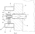
- stabilizer 4 Although only one stabilizer 4 is shown here by way of example, it is also possible for a plurality of stabilizers 4 to be arranged on the outer sides of the two furnace walls 3 in order to increase the stabilizing effect. Depending on the operating parameters and furnace construction but can also be dispensed with stabilizers. Furthermore, in each case on the outside of the two furnace walls 3, a rinsing system 70 for rinsing also arranged there rolling bearing unit 60. The rolling bearing unit 60 on the outside of the two outer walls 3 of the furnace chamber 5 serves respectively receiving and supporting one of the two ends of the individual rollers. 2 of the continuous furnace 1.
- rollers 2 can be stored in the rolling bearing units 60 outside the furnace chamber 5, 3 openings 6 are formed in the furnace walls, through which the individual rollers 2 are each out of the oven chamber 5 out into the associated roller bearing unit 60 ,
- An integral part of the rolling bearing units 60 for receiving and supporting the individual rollers 2 on both sides are rolling bearings 61, 62.
- the bearings 61,62 designed as ball bearings. However, other known Wälzlagerformen are also possible. Between the individual balls of the ball bearings 61,62 cavities are formed, which are filled with a lubricant (not shown).
- This circlip 65 is, for example, a corresponding standard part according to DIN 471. However, other fuses for the outer ball bearing 62 can also be used.
- the flushing system 70 With the rolling bearing unit 60, the flushing system 70 is connected.
- a component of this flushing system 70 is a piping system 71, which is arranged below the roller bearing unit 60 and which is connected via a feed line 72 to the cavity 63 of the rolling bearing pair 61, 62 of the roller bearing unit 60.
- a flow meter 73 and a control element 74 Integrated into the supply line 72 are a flow meter 73 and a control element 74.
- a piping system 71 for the purge gas for example, separate gas lines can be installed on the outside of the furnace wall 3. But it is also possible, by design already existing pipes or housing of the continuous furnace 1, which are arranged according to the already described stabilizers 4 as further stabilizers 4 on the outside of the furnace wall 3, to use as a piping system 71 for the purge gas.
- the supply line 72 can be connected, for example, in each case via plug connections to the cavity 63 and the pipeline system 71. But there are also other types of connection possible.
- a conditioned flushing gas is fed into the piping system 71.
- the purge gas may be, for example, a shielding gas for furnaces with a protective gas atmosphere or else an air stream for furnaces with air. But other gases are also usable as purge gas.
- the purge gas is provided in the piping system 71 at a pressure that produces a gas flow in the order of about 10 liters per hour.
- the flow rate of the purge gas can be read and monitored according to the flow meter 73.
- Regulation of the gas flow takes place by means of the control element 74, which in the simplest case is a throttle or an adjustment valve for the manual adjustment of the gas flow.
- the control element 74 also usable as the control element 74 are adjustable nozzles or orifices with which the flow velocity of the purge gas can be influenced, for example by varying the shape and size of the nozzle or orifices.
- the purge gas is introduced from the piping system 71 via the supply line 72 into the cavity 63 of the ball bearing pair.
- the inner ball bearing 61 is correspondingly flowed.
- the purge gas flows through the impinged inner ball bearing 61 by penetrating on the side of the inner ball bearing 61, which is aligned with the cavity 63 in the inner ball bearing 61 and exits on the side of the inner ball bearing 61, which is aligned with the furnace wall 3, again.
- a simultaneous flow through the outer ball bearing 62 is not possible because the outer ball bearing 62 can not be flowed through by the sealing element 64 from the purge gas.
- the purge gas can then continue to flow through the opening 6 in the furnace wall 3 into the interior of the furnace chamber 5.
- the entire flow path of the purge gas from the piping system 71 through the supply line 72 into the cavity 63 and then further through the inner ball bearing 61 and through the opening 6 in the furnace wall 3 into the furnace chamber 5 is indicated by arrows. Since neutral gas such as nitrogen or argon is always used as the purge gas or the purge gas, purge gas or purge gas introduced into the furnace chamber also serves as an inert gas when the required hydrogen to water ratio is maintained as described above.
- the set pressure of the purge gas can be reliably and effectively prevented that furnace gas flows from the furnace chamber 5 through the opening 6 and through the inner ball bearing 61.
- the temperature of the purge gas is substantially lower than the temperature of the furnace gas, since it is brought to the outside of the continuous furnace 1 to the rolling bearing unit 60, so that the lubricant does not dissolve during the flow.
- the piping system 71 only needs one port for supplying the purge gas into the piping system 71, although a plurality of ports may be provided therefor, it supplies a plurality of inner ball bearings 61 with purge gas, thereby ensuring that the wear of all the inner ball bearings 61 accordingly is reduced.
Landscapes
- Engineering & Computer Science (AREA)
- Mechanical Engineering (AREA)
- Chemical & Material Sciences (AREA)
- General Engineering & Computer Science (AREA)
- Physics & Mathematics (AREA)
- Thermal Sciences (AREA)
- Crystallography & Structural Chemistry (AREA)
- Materials Engineering (AREA)
- Metallurgy (AREA)
- Organic Chemistry (AREA)
- Manufacturing & Machinery (AREA)
- Tunnel Furnaces (AREA)
Description
- Die Erfindung betrifft ein Verfahren zum Betrieb eines Ofens zur Wärmebehandlung von metallischen Bauteilen, speziell zum Löten oder Sintern, insbesondere zum Hochtemperaturlöten. Weiterhin betrifft die Erfindung einen Ofen zum Durchführen des Verfahrens.
- Unter Löten versteht man das stoffschlüssige Fügen von Metallen, bei dem die Oberfläche des Grundwerkstoffes nicht aufgeschmolzen wird. Nur das metallische Lot liegt während des Prozesses in flüssiger Form vor. Es wird zwischen Weich-, Hart- und Hochtemperaturlöten unterschieden, wobei das Kriterium für die Einteilung die Liquidustemperatur des Lotes ist. Bis zu einer Liquidustemperatur von 450°C spricht man von Weichlöten, ab 450°C von Hartlöten. Lötvorgänge mit einer Liquidustemperatur von über 900°C fallen dabei unter den Begriff Hochtemperaturlöten.
- Grundlagen des Lötens sind beispielsweise in Pfeifer, Nacke, Beneke: Praxishandbuch Thermoprozess-Technik / Bd. 2. Anlagen - Komponenten - Sicherheit (ISBN 978-3-8027-2955-3) offenbart.
- Löten kommt nach Jahren des Rückgangs in vielen Wirtschaftszweigen wieder vermehrt zum Einsatz. Ein großes Gebiet sind Wärmetauscher, die im Zuge des Umweltschutzes zur Wärmerückgewinnung bei unterschiedlichen streng voneinander zu trennenden Medien die bei weitem häufigste Anwendung für das Ofenlöten finden. Dabei ist das Ofenlöten ein Lötverfahren, bei dem die Fügeteile in einem Ofen mit eingelegtem Lot aufgeheizt werden. Die Oberflächen der Fügeteile müssen regelmäßig vor dem Lötvorgang gereinigt. Um ein oxydieren der gereinigten Fügeteile zu verhindern, wird üblicherweise unter Schutzgas oder im Vakuum gelötet. Die Luft im Ofen wird evakuiert und/oder dieser mit einem Schutzgas gefüllt. Die Vorteile des Ofenlötens liegen im spannungs- und verzugsfreien Löten durch gleichmäßige Erwärmung der Fügeteile. Es werden beliebig viele Lötstellen unter Verzicht auf Flussmittel in einem Arbeitsgang gefertigt. Eine gleichzeitige Wärmebehandlung der Grundwerkstoffe ist in einem Arbeitsgang ebenfalls möglich.
- Für das Ofenlöten geeignete Öfen sind chargenweise arbeitende Geräte wie Kammeröfen oder kontinuierlich arbeitende Öfen mit einem Mittel zum Transport des Lötgutes durch den Ofen, wie beispielsweise ein Förderband oder angetriebene Rollen.
- Voraussetzung für das Herstellen einer Lötverbindung sind metallisch reine und oxidfreie Oberflächen, ohne die eine Benetzung mit Lot unmöglich ist. Bei Anwesenheit eines Elektrolyten (z. B. Feuchtigkeit) entstehen galvanische Elemente wie ein Lokalelement, die zu verstärkter Korrosion führen können. Lokalelemente sind kleinflächige Korrosionselemente (oder Kontaktelemente), die mit bloßem Auge kaum zu erkennen und deutlich kleiner als 1 mm2 sind.
- Die Bildungsenthalpie ist für die meisten Metalloxide negativ, d.h. sie sind in einer Sauerstoffatmosphäre stabil. Im Gegensatz dazu sind die Metalle instabil.
- Meist werden die zu verlötenden Blechteile gefettet und in Form gepresst. Das Fett muss vor dem Lötprozess entfernt werden. Großserien-Aluminium-Wärmetauscher werden ausschließlich in automatischen CAFB-Lötanlagen (Controlled Atmosphere Flux-Brazing-Lötanlagen) gelötet. Das Verfahren eignet sich ebenso wie das VAB-Verfahren (Vacuum Atmosphere Brazing-Verfahren) für das Löten von Stahl, Edelstahl, Kupfer, Nickel sowie edlere Metalle. Als Ursache dafür sind die Oxide der Metalloberflächen zu sehen, welche sich bei einem bestimmten Sauerstoff-Partialdruck bilden. Da die Neigung zur Oxidation bei Metallen mit zunehmender Temperatur steigt, müssen beim Lötprozess Gegenmaßnahmen ergriffen werden, die auf das angewendete Lötverfahren abgestimmt sind.
- Eine Möglichkeit der Verhinderung von Oxidschichten ist das Löten im Vakuumofen. Das Metalloxid löst sich durch dessen geringen Dampfdruck auf und eine Diffusion des Lotes ist nach Erreichen des Schmelzpunktes möglich. Solche Öfen sind allerdings in der Herstellung und im Betrieb sehr aufwändig.
- Eine weitere Möglichkeit ist die Verwendung von Schutzgasen. Dabei ist die Verwendung von Wasserstoff als Schutzgas wünschenswert. Wasserstoff hat eine um ca. 7-fach höhere Wärmeleitfähigkeit gegenüber dem üblichen Mischungsgas Stickstoff. Darüber hinaus wirkt Wasserstoff als Reduktionsmittel. Bei einer bestimmten Temperatur stellt sich ein Gleichgewicht zwischen Wasserstoff und Sauerstoff in Form von H2/H2O ein, wodurch die Qualität der Atmosphäre durch einfache Bestimmung des Taupunktes gemessen und geregelt werden kann. Für das Löten von Edelstählen mit einem Chromgehalt von bis zu 18 % ist ein Taupunkt von ca. - 50 °C erforderlich. Eine wichtige Größe stellt der prozentuale Gehalt des Wasserstoffs in der Atmosphäre dar, da für das H2/H20-Verhältnis nur die absoluten Werte maßgebend sind.
- Wasserstoff ist allerdings relativ teuer, so dass ein Verschleppen von Wasserstoff aus dem Ofen heraus minimiert werden sollte. Darüber hinaus bildet Wasserstoff in Verbindung mit Sauerstoff das hochexplosive Knallgas, so dass der Austritt von freiem Wasserstoff in die Atmosphäre außerhalb des Ofens nur in geringem Maße hinnehmbar ist. Im Stand der Technik sind zur Reduktion der Wasserstoffverschleppung Flammvorhänge an den Ein- und Ausfuhröffnungen solcher Öfen bekannt, in denen austretender Wasserstoff abfackelt. Solche Flammvorhänge können aber Schäden an den Bauteilen hervorrufen. Zumindest an der Einfuhröffnung sind die Bauteile noch nicht verlötet und daher empfindlich gegenüber einem unkontrollierten Wärmeeintrag. Darüber hinaus verbraucht ein solcher Ofen erhebliche Mengen Wasserstoff.
- Aus der
FR 2 333 866 A1 DE 10 2009 051 183 A1 ist ein Wärmebehandlungsofen zum Löten von wenigstens einem Bauteil mit einem Ofenkanal mit einer Einfuhröffnung und einer Ausfuhröffnung, einer Fördereinrichtung zum Bewegen des wenigstens einen mit Wärme zu behandelnden Bauteiles in dem Ofenkanal und einem mit Schutzgas gefüllten Wärmebehandlungsabschnitt des Ofenkanals bekannt. Weiterhin weist der Wärmebehandlungsofen eine Heizeinrichtung zum Erwärmen des Schutzgases und/oder der Bauteile in dem Wärmebehandlungsabschnitt auf Der Wärmebehandlungsofen ist als Buckelofen ausgebildet, wobei der Wärmebehandlungsabschnitt des Ofens gegenüber jeweils einem Trennabschnitt an der Ein- und Ausfuhröffnung höher angeordnet ist. Die Einfuhröffnung mündet in einen Trennabschnitt des Ofenkanales. Die Bauteile werden dabei in dem Trennabschnitt mit einer Bewegungskomponente nach oben in dem Trennabschnitt gefördert. Der Trennabschnitt weist somit eine Steigung auf und mündet in den Wärmebehandlungsabschnitt. In dem Wärmebehandlungsabschnitt mit einer Heizeinrichtung ist Wasserstoff als Schutzgas vorgesehen. In dem Wärmebehandlungsabschnitt werden die Bauteile und das Schutzgas auf hohe Temperaturen, z. B. für Bauteile aus Aluminium auf 600°C oder für Bauteile aus Edelstahl auf bis zu 1200°C, erwärmt und dort beispielsweise verlötet. Die Heizeinrichtung erwärmt dabei sowohl das Schutzgas als auch die Bauteile aufgrund einer Wärmestrahlung aus der Heizeinrichtung. Der im Wesentlichen horizontal ausgerichtete Wärmebehandlungsabschnitt mündet anschließend in einen Ofenkanal, der ein Gefälle aufweist, d. h. die Bauteile werden mit einer Bewegungskomponente nach unten gefördert. Am Ende des Ofenkanales nach dem Wärmebehandlungsabschnitt treten die Bauteile aus einer Ausfuhröffnung wieder in die Umgebungsatmosphäre aus. In den Trennabschnitten ist Stickstoff als Trenngas enthalten. Wasserstoff weist im Normalzustand eine geringere Dichte als Stickstoff auf, so dass sich innerhalb des Ofenkanales das Trenngas unterhalb des Schutzgases anordnet. Zwischen dem Trenngas und dem Schutzgas bildet sich somit in dem Ofenkanal eine Grenzfläche aus. Eine Vorhangbox mit Fäden bzw. Streifen in dem Ofenkanal im Bereich der Einfuhröffnung verhindert, dass größere Mengen an Trenngas aus der Einfuhröffnung austreten. Durch eine Einlassöffnung für Stickstoff wird das Trenngas in den Trennabschnitt eingeführt. In analoger Weise wird in den Ofenkanal durch eine Einlassöffnung Wasserstoff als Schutzgas im Bereich der Ausfuhröffnung eingeleitet. Das kontinuierliche Einleiten von Schutzgas in den Ofenkanal und damit auch in den Wärmebehandlungsabschnitt ist erforderlich, damit das Schutzgas in einer ausreichend reinen Konzentration in dem Wärmebehandlungsabschnitt während des Betriebes des Wärmebehandlungsofens vorliegt. Der Überschuss an Schutzgas tritt dabei in einen Seitenkanal und von dort in einen Abzugskanal ein. Der Abzugskanal weist dabei Luftzuführöffnungen auf. Durch die Luftzuführöffnungen wird dem Abzugskanal Luft zugeführt und an einem Ende des Abzugskanals wird das überschüssige Schutzgas verbrannt. Auch in den Trennabschnitt wird kontinuierlich durch die Einlassöffnung Stickstoff zugeführt. Dies ist erforderlich, damit in dem Trennabschnitt das Trenngas in ausreichender reiner Konzentration vorhanden ist. Der Überschuss an Trenngas tritt dabei sowohl durch die Einfuhröffnung als auch teilweise durch den Abzugskanal in die Umgebung aus. Ein Teil des Überschusses an Schutzgas wird neben dem Abzugskanal auch aus der Ausfuhröffnung ausgeleitet. Um an der Ausfuhröffnung möglichst wenig Schutzgas auszuleiten, ist an dieser Stelle eine Vorhangbox angeordnet. Damit tritt an der Ausfuhröffnung eine Grenzfläche zwischen dem Schutzgas und der Umgebungsatmosphäre auf, so dass an der Ausfuhröffnung ein Flammvorhang vorgesehen ist. Ein derartiger Flammvorhang an der Ausfuhröffnung führt zwar im Allgemeinen an den Bauteilen zu kleinem Schaden, weil an der Ausfuhröffnung die Bauteile bereits mit Wärme behandelt sind, bewirkt aber einen hohen Verbrauch an Schutzgas. Darüber hinaus verbraucht dieser Ofen große Mengen an Trenngas. - Ein weiterer Nachteil des Buckelofens ist darin zu sehen, dass die Bauteile nicht nur horizontal, sondern auch schräg nach oben beziehungsweise schräg nach unten bewegt werden, wodurch sich zu verlötende Teile in ihrem ungelöteten Zustand und wenn das Lot im zumindest teilaufgeschmolzenen Zustand noch weich ist, intern verschieben können.
- Aufgabe der Erfindung ist es daher, ein Verfahren zur Wärmebehandlung in Form von Löten oder Sintern eines metallischen Bauteils unter einem Wasserstoff enthaltenden Schutzgas bereitzustellen, wobei eine ausreichende Reinheit der Atmosphäre zumindest in dem Abschnitt des Ofens bereit steht, in dem die Lötung oder Sinterung erfolgt, und wobei der Verbrauch von Schutzgas minimiert wird.
- Weiterhin ist es Aufgabe der Erfindung, einen Durchlaufofen zur Durchführung des Verfahrens anzugeben.
- Erfindungsgemäß wird diese Aufgabe durch ein Verfahren mit den Merkmalen des unabhängigen Anspruches 1 gelöst. Vorteilhafte Weiterbildungen des Verfahrens ergeben sich aus den Unteransprüchen 2 bis 5. Die Aufgabe wird ferner durch einen Durchlaufofen nach Anspruch 6 gelöst. Vorteilhafte Ausführungsformen des Durchlaufofens ergeben sich aus den Unteransprüchen 7 bis 11.
- Erfindungsgemäß wird zur Wärmebehandlung eines metallischen Bauteils dieses zunächst in eine Vakuumkammer eingebracht. Die Kammer wird geschlossen und Vakuum gezogen. Nach Erreichen eines zuvor definierten Unterdrucks, beispielsweise von 10 bis 100 mbar wird die Vakuumkammer zu einem angrenzenden Wärmebehandlungsabschnitt, der mit einem Wasserstoff enthaltenden Schutzgas gefüllt ist, geöffnet und das metallische Bauteil in diesen Abschnitt verbracht. Dort erfährt das Bauteil unter der Schutzgasatmosphäre seine Wärmebehandlung. Da der Wasserstoff aus den Metalloxiden den Sauerstoff durch Bildung von H2O löst, steigt der Taupunkt der Schutzgasatmosphäre unzulässig an. Der Wasserstoff aus dem Wärmebehandlungsabschnitt wird deshalb in einem Molekularsieb gereinigt. Bei dieser Reinigung werden dem Wasserstoff Wassermoleküle entzogen. Ein geeignetes Molekularsieb weist dabei in seinem Inneren Zeolithe, das heißt kristalline Alumosilikate, auf, die eine große innere Oberfläche besitzen. Es werden dabei Oberflächen von beispielsweise ca. 600 - 700 m2/g erreicht. Die Zeolithe weisen einen im Wesentlichen einheitlichen Porendurchmesser in der Größenordnung der zu filternden Moleküle auf. Für die Filterung von Wassermolekülen hat sich ein Porendurchmesser von ca. 0,3 - 0,4 nm als geeignet erwiesen. Nach erfolgter Wärmebehandlung wird das metallische Bauteil erneut in eine Vakuumkammer verbracht, in der nach dem Schließen der Kammer Vakuum gezogen wird. Nach Erreichen eines zuvor definierten Unterdrucks von beispielsweise 10- 100 mbar wird die Vakuumkammer zur Außenatmosphäre hin geöffnet und das metallische Bauteil aus dem Durchlaufofen transportiert. Durch das Evakuieren vor und nach der Wärmebehandlung wird vermieden, dass sich das Schutzgas mit anderen Gasen, insbesondere mit Luftsauerstoff, vermischen kann. Darüber hinaus entweichen keine größeren Mengen Wasserstoff in die Atmosphäre außerhalb des Durchlaufofens, wodurch der Explosions- oder Brandgefahr vorgebeugt wird und der Wasserstoffverbrauch des Durchlaufofens minimiert wird. Durch die Reinigung des Schutzgases steht ausreichend reines recyceltes Schutzgas für den Prozess zur Verfügung.
- In einer vorteilhaften Ausführungsform wird der Wasserstoff aus dem Wärmebehandlungsabschnitt kontinuierlich während der Wärmebehandlung gereinigt. Alternativ kann der Wasserstoff aber auch diskontinuierlich gereinigt werden. Dazu hat es sich als vorteilhaft erwiesen, wenn durch eine Taupunktmessung der Ofenatmosphäre der Reinigungsbedarf ermittelt wird und die Reinigung bei Erreichen eines zuvor definierten Grenzwertes, beispielsweise zwischen -30 und -50°C, gestartet wird. Dies kann geschehen, indem erst bei Erreichen dieses Grenzwertes das Schutzgas aus dem Wärmebehandlungsabschnitt abgesaugt, gereinigt, und dem Wärmebehandlungsabschnitt wieder zugeführt wird. Dabei wird das Schutzgas aus einem Endbereich des Wärmebehandlungsabschnitts abgesaugt, und das gereinigte Schutzgas in einem Mittelbereich des Wärmebehandlungsabschnitts wieder zugeführt. In einer vorteilhaften Ausführungsform schließt die Wärmebehandlung ein Lötverfahren ein. Dabei besteht das metallische Bauteil aus mindestens zwei Einzelteilen, die an einander angrenzen und durch ein Lotmaterial, das sich beispielsweise pastenförmig zwischen den Einzelteilen befindet, voneinander beabstandet sind. Es können auch Ringe oder Folien aus Lot verwendet werden. Während der Wärmebehandlung schmilzt das Lot auf und diffundiert in die Oberflächen der Einzelteile ein.
- Ein erfindungsgemäßer Durchlaufofen weist einen Wärmebehandlungsabschnitt auf, der eine Ofenatmosphäre aufweist, die mit Wasserstoff als Schutzgas geflutet werden kann, und weist weiter einen Endbereich und einen Mittenbereich auf, wobei mindestens eine Vakuumkammer an den Wärmebehandlungsabschnitt angrenzt, und wobei die Vakuumkammer gasdicht mit dem Wärmebehandlungsabschnitt verbunden ist, und wobei der Durchlaufofen weiterhin ein Molekularsieb zum Ausfiltern von Wassermolekülen aus dem die Ofenatmosphäre bildenden Gas aufweist.
- Es hat sich als vorteilhaft erwiesen, wenn der Durchlaufofen zwei Vakuumkammern aufweist, wobei eine Vakuumkammer in Durchlaufrichtung vor und eine Vakuumkammer in Durchlaufrichtung nach dem Wärmebehandlungsabschnitt angeordnet ist. Mit einer solchen Anordnung ist es möglich zu verhindern, dass größere Mengen Gas aus der Atmosphäre außerhalb des Ofens in die Ofenkammer gelangen und sich mit dem Schutzgas, das sich in der Ofenkammer befindet, vermischen. Ebenso kann verhindert werden, dass größere Mengen Schutzgas aus der Ofenkammer in die Atmosphäre außerhalb des Ofens entweichen. Schutzgas kann eingespart werden, und außerhalb des Ofens bildet sich keine eventuell explosive Mischung von Schutzgas und Luftsauerstoff.
- In einer weiteren Ausführungsform weist der Durchlaufofen ein Mittel zur Taupunktmessung der Ofenatmosphäre auf. Durch die Messung des Taupunkts kann bestimmt werden, wann die Atmosphäre gereinigt werden sollte. Der Durchlaufofen weist einen Endbereich des Wärmebehandlungsabschnitts auf, wobei der Endbereich eine Entnahmeöffnung für den Wasserstoff aus der Ofenatmosphäre aufweist. Der Wasserstoff kann durch das Molekularsieb geleitet werden und in gereinigter Form der Ofenatmosphäre wieder zugesetzt werden. Dies geschieht in einem Mittenbereich des Wärmebehandlungsabschnitts wobei dieser Mittenbereich dazu eine Zuführungsöffnung aufweist.
- Ein Vorteil des erfindungsgemäßen Ofens ist die im Wesentlichen horizontale Fördertechnik, wodurch die Gefahr des gegenseitigen Verrutschens der Lötbaugruppen minimiert ist. Weiterhin weist der erfindungsgemäße Ofen eine nahezu uneingeschränkte Durchgangshöhe für die der Wärmebehandlung zu unterziehenden Metallteile auf. Durch den Schleusenbetrieb mit den vor- und nachgeschalteten Vakuumkammern wird der Gasverbrauch minimiert, was sich insbesondere bei hohen zu behandelnden Metallteilen positiv bemerkbar macht, da der Schutzgasverbrauch mit der vierten Potenz der Durchgangshöhe steigt. Bei konventionellen Öfen wird der Prozess aus dieser Sicht sehr schnell unwirtschaftlich.
- In einer weiteren Ausführungsform weist der Durchlaufofen mindestens eine antreibbare Rolle zum Transport eines metallischen Bauteils auf. Besonders bevorzugt ist diese Rolle durch die seitlichen Ofenwände hindurchgeführt und in einer Wälzlagereinheit außerhalb der Ofenkammer aufgenommen. Üblicherweise sind die Lager als Kugellager ausgebildet. Da die Temperatur an der Außenseite der Ofenwand der Ofenkammer nur etwa 100°C beträgt, können Kugellager mit Schmierstoffen im Inneren zum Einsatz kommen, die die Laufeigenschaften der Kugellager verbessern, sowie deren Lebensdauer verlängern.
- Es hat sich als vorteilhaft erwiesen, wenn der Rollenherdofen ein Spülsystem für die Wälzlagereinheit aufweist, das dazu ausgebildet ist, ein Spülgas durch die Wälzlagereinheit zu leiten, wobei das Spülgas von einer von der Ofenwand abgewandten Seite der Wälzlagereinheit durch die Wälzlagereinheit und durch die Öffnung der Ofenwand hindurch in die Ofenkammer des Rollenherdofens leitbar ist und wobei das Spülgas mit einem Druck bereitstellbar ist, der größer ist als ein Innendruck in der Ofenkammer des Rollenherdofens. Während des Betriebs des Rollenherdofens führen Verschmutzungen des Schmierstoffes und/oder Verringerungen der Schmierstoffmenge häufig zu einer Reduzierung der Lebensdauer der Kugellager für die Rollen. Ursache dafür kann beispielsweise aus dem Rollenherdofen austretendes Ofengas sein, das durch die Öffnungen in der Ofenwand aus der Ofenkammer nach außen gelangt und dabei auch durch die an der Außenseite der Ofenwand angeordneten Kugellager strömt. Dabei werden die während der Rollendrehungen und der damit verbundenen Reibung an der keramischen Isolierwand im Ofen entstehenden Partikel durch das Ofengas teilweise mit nach außen befördert und beim Durchströmen in die Kugellager eingetragen. Bedingt durch die hohe Temperatur des Ofengases sowie der Beladung mit aerosolen Keramikpartikeln wird außerdem der Schmierstoff langsam aufgelöst, sodass sich die Schmierstoffmenge zeitabhängig entsprechend reduziert. Durch die beschriebene Spülung der Wälzlagereinheit wird die Lebensdauer der Wälzlager deutlich verbessert. Darüber hinaus ist der Austritt von Ofengas in die Außenatmosphäre wegen des dadurch erhöhten Gasverbrauchs und der eventuellen Bildung einer explosionsfähigen Gasmischung nicht möglich. Durch die beschriebene Spülung der Wälzlagereinheit wird dem Austritt von Ofengas in die Außenatmosphäre entgegen gewirkt. Als Spülgas kann beispielsweise Stickstoff eingesetzt werden.
- Durch das Spülgas wird die Hinterisolierung der Wärmedämmung des Ofenkörpers bis zu einer vorgesehenen metallischen Diffusionssperre wasserstofffrei gespült, wodurch die Außenwandtemperatur des Ofenkörpers geringer wird und eine Energieeinsparung möglich wird. Beispielsweise weist Stickstoff nur ca. ein Siebtel der Wärmeleitfähigkeit von Wasserstoff auf. Wird Stickstoff als Spülgas eingesetzt, wird die thermische Isolierfähigkeit um nahezu das Siebenfache verbessert, wodurch die Außenwandtemperatur des Ofenkörpers signifikant erniedrigt und eine deutliche Energieeinsparung erreicht wird.
- Eine weitere Ausführungsform der Lagerung beinhaltet eine Sperrgaskammer, über die die Dichtigkeit der Lagereinheit stets überprüft wird.
- Weitere Vorteile, Besonderheiten und zweckmäßige Weiterbildungen der Erfindung ergeben sich aus den Unteransprüchen und der nachfolgenden Darstellung bevorzugter Ausführungsbeispiele anhand der Abbildungen.
- Von den Abbildungen zeigt:
- Fig. 1
- Ellingham-Richardson-Diagramm
- Fig. 2
- einen erfindungsgemäßen Durchlaufofen in schematischer Darstellung
- Fig. 3
- Lagerung einer Rolle eines erfindungsgemäßen Durchlaufofens
- Die Bildungsenthalpie ist für die meisten Metalloxide negativ, d.h. sie sind in einer Sauerstoffatmosphäre stabil. Im Gegensatz dazu sind die Metalle instabil. Zur Veranschaulichung der Bedingungen, unter denen ein Oxid gebildet werden kann, wurde das Ellingham-Richardson-Diagramm eingeführt (
Fig. 1 ). In diesem Diagramm ist die Bildungsenthalpie ΔG0 als Funktion der Temperatur dargestellt. Anhand dieser Auftragung kann man Aussagen zur relativen Stabilität der Oxide machen. Die Stabilität des Oxids nimmt mit Abnahme der ΔG0 -Werte zu. Mit zunehmender Temperatur steigen die Kurven an, da die Oxidbildung eine Abnahme der Entropie und damit einen Anstieg der Enthalpie zur Folge hat. Auf der rechten Seite des inFig. 1 dargestellten Diagramms kann man den Dissoziationsdruck des Oxids bestimmen. Dafür wird eine Linie gezogen, ausgehend vom Punkt "O" auf der linken Seite des Diagramms über den ΔG0 -Wert für eine bestimmte Temperatur bis zur pO2 - Skala auf der rechten Seite. Der Schnittpunkt mit der pO2 - Linie gibt den Dissoziationsdruck für das Oxid an. Beispielsweise sind die Verhältnisse für Fe/FeO bei 1.200°C in das Diagramm derFigur 1 eingetragen. Ausgehend von der Temperatur 1.200°C bildet der Punkt "A" den ΔG0 -Wert. Die Gerade von "O" durch "A" schneidet die pO2 - Skala im Punkt "B", an dem ein Dissoziationsdruck für FeO von 10-12 atm abgelesen werden kann. Die Verlängerung dieser Linie schneidet die H2/H2O-Verhältnisskala im Punkt "C" zwischen 103 und 104, so dass man bei einem H2/H2O-Verhältnis von 104 auf der sicheren Seite liegt, um die Bildung von FeO verhindern zu können. -
Fig. 2 ist die schematische Darstellung eines erfindungsgemäßen Durchlaufofens. Ein metallisches Bauteil 50 wird in Pfeilrichtung auf Rollen 2 durch den Ofen gefahren. Dabei kann das metallische Bauteil 50 ein einzelnes Bauteil sein, das beispielsweise für eine Sinterbehandlung dem Durchlaufofen 1 zugeführt wird. Die Wärmebehandlung kann auch ein Lötverfahren einschließen. Dabei besteht das metallische Bauteil 1 aus mindestens zwei Einzelteilen, die an einander angrenzen und durch ein Lotmaterial, das sich beispielsweise pastenförmig zwischen den Einzelteilen befindet, voneinander beabstandet sind. Während der Wärmebehandlung schmilzt das Lot auf und diffundiert in die Oberflächen der Einzelteile ein. Der Ofen besitzt eine Vakuumkammer 20, die in Durchlaufrichtung vor der Ofenkammer 5 angeordnet und gasdicht mit dieser verbunden ist. Die Vakuumkammer 20 weist eine gasdicht verschließbare Tür 25 zur Außenatmosphäre hin und eine weitere gasdicht verschließbare Tür 26 zur Ofenkammer 5 hin auf. Das metallische Bauteil 50 wird auf den Rollen 2 nach Öffnung der zur Außenatmosphäre hin gelegenen Tür 25 in die Vakuumkammer 20 hinein transportiert. Gleichzeitig kann Luft aus der Außenatmosphäre in die Vakuumkammer 20 hinein strömen. Die Tür 25 schließt und anschließend wird Vakuum gezogen. Der erreichte Unterdruck kann an einem Manometer 22 abgelesen werden. nach Erreichen eines Sollunterdrucks von beispielsweise 10 - 100 mbar wird die Tür 26 zur Ofenkammer 5 hin geöffnet und das metallische Bauteil 50 auf den Rollen 2 in die Offenkammer 5 verbracht. Die Tür 26 kann anschließend wieder verschlossen werden. Während der Öffnung der Tür 26 strömt Gas aus der Ofenkammeratmosphäre in die Vakuumkammer 20. Die Ofenkammer 5 weist Mittel zur Beheizung des metallischen Bauteils 50 auf (nicht gezeigt). Dabei kann es sich um Strahlungsheizungen handeln. Diese Heizungen heizen nicht nur das metallische Bauteil 50 auf eine für den jeweiligen Wärmebehandlungsprozess erforderliche Temperatur auf, sondern auch das Gas in der Kammeratmosphäre. Neben Strahlungsheizungen sind auch alle anderen geeigneten Heizungsarten vorstellbar. - Die Ofenkammeratmosphäre 11 besteht aus einem Schutzgas 100, beispielsweise aus Wasserstoffgas. Auch eine Mischung aus Wasserstoffgas plus einem neutralgas wie beispielsweise Stickstoff oder Argon kann als Schutzgas benutzt werden, wobei der erforderliche niedrige Wassergehalt sich stets auf den Wasserstoffanteil bezieht. Dieses Schutzgas 100 muss in einer ausreichenden Reinheit vorliegen. In der Ofenatmosphäre 11 eventuell vorhandener Sauerstoff wird mit dem Wasserstoff des Schutzgases 100 Wasser bilden. Der Taupunkt der Ofenatmosphäre 11 ist daher ein Indikator für die Reinheit des Schutzgases 100 in der Ofenatmosphäre 11. Der Taupunkt kann mit bekannten Mitteln mit geringem Aufwand gemessen werden, so dass über eine Taupunktmessung die Reinheit der Ofenatmosphäre 11 leicht bestimmbar ist.
- Der Durchlaufofen 1 weist einen Endbereich 12 des Wärmebehandlungsabschnitts 10 auf, wobei der Endbereich 12 eine Entnahmeöffnung für das Schutzgas 100 aus der Ofenatmosphäre 11 aufweist. Weiterhin weist der Durchlaufofen 1 ein Molekularsieb 30 auf, das sich außerhalb der Ofenkammer 5 befindet. Das durch die Entnahmeöffnung des Endbereichs 12 entnommene Schutzgas 100 wird in dem Molekularsieb 30 gereinigt. Bei dieser Reinigung werden dem Schutzgas 100 Wassermoleküle entzogen. Ein geeignetes Molekularsieb 30 weist dabei in seinem Inneren Zeolithe, das heißt kristalline Alumosilikate, auf, die eine große innere Oberfläche besitzen. Es werden dabei Oberflächen von beispielsweise ca. 600 - 700 m2/g erreicht. Die Zeolithe weisen einen im Wesentlichen einheitlichen Porendurchmesser in der Größenordnung der zu filternden Moleküle auf. Für die Filterung von Wassermolekülen hat sich ein Porendurchmesser von ca. 0,3- 0,4 nm als geeignet erwiesen.
- Der Durchlaufofen 1 weist weiterhin einen Mittenbereich 13 des Wärmebehandlungsabschnitts 10 auf, wobei der Mittenbereich 13 des Wärmebehandlungsabschnitts 10 eine Zuführungsöffnung aufweist, durch die das Schutzgas 100 in gereinigter Form der Ofenatmosphäre 11 wieder zugesetzt werden kann.
- Das Schutzgas 100 kann dem Wärmebehandlungsabschnitt 10 kontinuierlich durch die Entnahmeöffnung entnommen, in dem Molekularsieb 30 gereinigt und der Ofenatmosphäre 11 durch die Zuführungsöffnung wieder zugeführt werden. Alternativ kann das Schutzgas 100 aber auch diskontinuierlich gereinigt werden. Dazu kann über eine Taupunktmessung der Ofenatmosphäre 11 der Reinigungsbedarf ermittelt und die Reinigung bei Erreichen eines zuvor definierten Grenzwertes gestartet werden. Der Grenzwert kann beispielsweise bei einem Verhältnis von Wasserstoff zu Wasser von mehr als 1.000 liegen. Dazu weist der Durchlaufofen 1 ein Mittel zur Taupunktmessung der Ofenatmosphäre 11 auf (nicht gezeigt). Bei Erreichen des Grenzwertes wird das Schutzgas 100 aus dem Wärmebehandlungsabschnitt 10 abgesaugt und dem Molekularsieb 30 zugeführt, darin gereinigt, und dem Wärmebehandlungsabschnitt 10 in gereinigter Form wieder zugeführt.
- Nach erfolgter Wärmebehandlung wird das metallische Bauteil 50 in eine Vakuumkammer 40, die sich in Durchlaufrichtung des metallischen Bauteils 50 durch den Durchlaufofen 1 hinter dem Wärmebehandlungsabschnitt 10 befindet, verbracht. Die Vakuumkammer 40 ist gasdicht mit dem Wärmebehandlungsabschnitt 10 verbunden und weist an ihrer dem Wärmebehandlungsabschnitt 10 zugewandten Seite eine Tür 46 auf. An ihrer entgegengesetzten Seite weist die Vakuumkammer 40 eine Tür 45 auf. Zur Einbringung des metallischen Bauteils 50 aus dem Wärmebehandlungsabschnitt 10 in die Vakuumkammer 40 wird die Tür 46 geöffnet und nach der Einbringung des metallischen Bauteils 50 wieder geschlossen. Anschließend wird Vakuum gezogen. Nach Erreichen eines zuvor definierten Unterdrucks von beispielsweise von 10 - 100 mbar wird die Tür 45 der Vakuumkammer 40 zur Außenatmosphäre hin geöffnet und das metallische Bauteil 50 aus dem Durchlaufofen 1 transportiert. Durch das Evakuieren vor und nach der Wärmebehandlung wird vermieden, dass sich das Schutzgas 100 mit anderen Gasen, insbesondere mit Luftsauerstoff, vermischen kann. Darüber hinaus entweichen keine größeren Mengen wasserstoffhaltiges Schutzgas 100 in die Atmosphäre außerhalb des Durchlaufofens 1, wodurch der Explosionsgefahr vorgebeugt wird und der Schutzgasverbrauch des Durchlaufofens 1 minimiert wird. Durch die Reinigung des Schutzgases 100 steht ausreichend reines Schutzgas 100 für den Prozess zur Verfügung.
- Die gesamte Anlage wird mit einem Überdruck von beispielsweise ca. 30 mbar gegenüber der Umgebung betrieben. Auf diese Art kann im Fall einer Leckage kein Luftsauerstoff eindringen und die Leckage schnell und zuverlässig lokalisiert werden.
- Der Durchlaufofen 1 weist mindestens eine antreibbare Rolle2 zum Transport eines metallischen Bauteils 1 auf. In
Fig. 3 ist die Lagerung einer Rolle eines erfindungsgemäßen Durchlaufofens dargestellt. Die Ofenkammer 5 des Rollenherdofens 1 weist auf beiden Seiten jeweils eine Ofenwand 3 zur seitlichen Begrenzung der Ofenkammer 5 auf. Die Rolle 2 ist durch die seitlichen Ofenwände 3 hindurchgeführt und in einer Wälzlagereinheit 60 außerhalb der Ofenkammer 5 aufgenommen. Jeweils an der Außenseite der beiden Ofenwände 3 der Ofenkammer 5 kann ein Stabilisator 4 zur mechanischen Stabilisierung der Ofenkammer 5 angeordnet sein. Diese mechanische Stabilisierung kann erforderlich sein, da das Material der Ofenwände 3 durch die teilweise sehr hohen Temperaturunterschiede zwischen dem Innenraum der Ofenkammer 5 und ihrer Umgebung großen thermischen Belastungen unterliegt, die zu Verformungen der Ofenwände 3 führen können. Obwohl hier beispielhaft nur ein Stabilisator 4 dargestellt ist, können aber auch mehrere Stabilisatoren 4 zur Erhöhung der Stabilisierungswirkung an den Außenseiten der beiden Ofenwände 3 angeordnet sein. Je nach Betriebsparametern und Ofenkonstruktion kann aber auch auf Stabilisatoren verzichtet werden. Weiterhin befindet sich jeweils an der Außenseite der beiden Ofenwände 3 ein Spülsystem 70 zum Spülen der ebenfalls dort angeordneten Wälzlagereinheit 60. Die Wälzlagereinheit 60 an der Außenseite der beiden Außenwände 3 der Ofenkammer 5 dient jeweils der Aufnahme und Lagerung eines der beiden Enden der einzelnen Rollen 2 des Durchlaufofens 1. Damit die Rollen 2 in den Wälzlagereinheiten 60 außerhalb der Ofenkammer 5 gelagert werden können, sind in den Ofenwänden 3 Öffnungen 6 ausgebildet, durch die die einzelnen Rollen 2 jeweils aus der Ofenkammer 5 heraus nach außen in die zugehörige Wälzlagereinheit 60 geführt werden. Ein wesentlicher Bestandteil der Wälzlagereinheiten 60 zur beidseitigen Aufnahme und Lagerung der einzelnen Rollen 2 sind Wälzlager 61,62. InFig. 3 sind die Wälzlager 61,62 als Kugellager ausgebildet. Andere bekannte Wälzlagerformen sind jedoch ebenso möglich. Zwischen den einzelnen Kugeln der Kugellager 61,62 sind Hohlräume ausgebildet, die mit einem Schmierstoff (nicht gezeigt) gefüllt sind. Dieser Schmierstoff hat insbesondere die Aufgabe, die während der Rollbewe-gungen der Kugeln auftretende Reibung zwischen den Kugeln und den beiden Ringen, auf der die Kugeln abrollen, zu verringern und dadurch die Verlustleistung und den Verschleiß des Kugellagers 61, 62 zu minimieren. Als Schmierstoff geeignet sind dabei alle bekannten Schmierstoffe und -fette, die in Wälzlagern üblicherweise zur Anwendung kommen. Da die Lagerung der Rolle 2 außerhalb der Ofenkammer 5 erfolgt, ist in der Ofenwand 3 eine Öffnung 6 ausgebildet, durch die die Rolle 2 aus der Ofenkammer 5 heraus nach außen in die zugehörige Wälzlagereinheit 60 geführt wird. Die Lagerung der Rolle 2 in der Wälzlagereinheit 60 wird über ein Kugellagerpaar realisiert, das aus einem inneren Kugellager 61 und einem äußeren Kugellager 62 gebildet wird. Dabei ist das innere Kugellager 61 des Kugellagerpaares näher an der Ofenwand 3 angeordnet als das äußere Kugellager 62 und beide Kugellager 61 und 62 sind so nebeneinander angeordnet, dass zwischen den beiden Kugellagern 61 und 62 des Kugellagerpaares ein Hohlraum 63 ausgebildet wird. Im Inneren des Hohlraumes 63 an der Seite des äußeren Kugellagers 62, die zum Hohlraum 63 ausgerichtet ist, ist ein Dichtelement 64 angeordnet. Aufgabe dieses Dichtelementes 64 ist es, den Hohlraum 63 so abzudichten, dass kein Spülgas aus dem Hohlraum 63 in das äußere Kugellager 62 eindringen kann. Dafür kann das Dichtelement 64 als Wellendichtring, beispielsweise als Radialwellendichtring, ausgebildet sein. Die Sicherung des äußeren Kugellagers 62 auf der Rolle 2 erfolgt über einen Sicherungsring 65, der am Ende der Rolle 2 montiert wird. Bei diesem Sicherungsring 65 handelt es sich beispielsweise um ein entsprechendes Normteil nach DIN 471. Es können aber auch andere Sicherungen für das äußere Kugellager 62 verwendet werden. - In einer weiteren Ausführungsform ist eine drucküberwachte Sperrgaskammer vorgesehen, mit deren Hilfe die Dichtigkeit der Lagereinheit stet überprüft werden kann. Dazu kann im Inneren des Hohlraums 63 einer Wälzlagereinheit 60 ein weiteres Dichtelement so angeordnet werden, dass eine Kammer ausgebildet wird. Mit einer an diese Kammer angeschlossenen Druckübenivachung besteht dann die Möglichkeit, den Druck in der Kammer zu überwachen und bei einem registrierten Druckabfall in dieser Kammer, die betroffene Wälzlagereinheit 60 entsprechend auszutauschen.
- Mit der Wälzlagereinheit 60 ist das Spülsystem 70 verbunden. Ein Bestandteil dieses Spülsystems 70 ist ein Rohrleitungssystem 71, das unterhalb der Wälzlagereinheit 60 angeordnet ist und das über eine Zuleitung 72 an den Hohlraum 63 des Wälzlagerpaares 61,62 der Wälzlagereinheit 60 angebunden ist. In die Zuleitung 72 integriert sind ein Strömungsmesser 73 sowie ein Steuerungselement 74.
- Als Rohrleitungssystem 71 für das Spülgas können an der Außenseite der Ofenwand 3 beispielsweise separate Gasleitungen installiert werden. Es ist aber auch möglich, konstruktionsbedingt bereits vorhandene Rohre oder Gehäuse des Durchlaufofens 1, die entsprechend den bereits beschriebenen Stabilisatoren 4 als weitere Stabilisatoren 4 an der Außenseite der Ofenwand 3 angeordnet sind, als Rohrleitungssystem 71 für das Spülgas zu nutzen.
- Die Zuleitung 72 kann beispielsweise als flexibler Gummi- oder Silikonschlauch ausgeführt werden. Es können aber auch feste Leitungen beispielsweise aus Kunststoff oder Metall installiert werden. Bei der Materialauswahl für die Zuleitung 72 sind vor allem die Anforderungen des verwendeten Spülgases hinsichtlich einer chemischen Beständigkeit sowie die geplanten Druckverhältnisse zu berücksichtigen.
- Für eine leichte und einfache Montage kann die Zuleitung 72 beispielsweise jeweils über Steckverbindungen mit dem Hohlraum 63 und dem Rohrleitungssystem 71 verbunden werden. Es sind aber auch andere Verbindungsarten möglich.
- Zum Spülen des inneren Kugellagers 61 wird in das Rohrleitungssystem 71 ein konditioniertes Spülgas eingespeist. In Abhängigkeit von der Art des Durchlaufofens 1 kann es sich bei dem Spülgas beispielsweise um ein Schutzgas für Öfen mit Schutzgasatmosphäre oder auch um einen Luftstrom für Öfen mit Luft handeln. Andere Gase sind aber ebenfalls als Spülgas verwendbar.
- Das Spülgas wird im Rohrleitungssystem 71 mit einem Druck bereitgestellt, der einen Gasstrom in einer Größenordnung von ungefähr 10l pro Stunde erzeugt. Die Strömungsgeschwindigkeit des Spülgases kann am Strömungsmesser 73 entsprechend abgelesen und überwacht werden. Eine Regulierung des Gasstromes erfolgt mittels des Steuerungselementes 74, bei dem es sich im einfachsten Fall um eine Drossel oder um ein Einstellventil zur manuellen Einstellung des Gasstromes handelt. Ebenfalls als Steuerungselement 74 verwendbar sind einstellbare Düsen oder Blenden, mit denen die Strömungsgeschwindigkeit des Spülgases beeinflusst werden kann, indem beispielsweise Form und Größe der Düsen- oder Blendenöffnungen variiert werden. Weiterhin besteht die Möglichkeit, ein komplexes Steuerungselement 74 zu installieren, über das eine automatische Steuerung des Gasstromes möglich ist.
- Durch den anliegenden Druck wird das Spülgas aus dem Rohrleitungssystem 71 über die Zuleitung 72 in den Hohlraum 63 des Kugellagerpaares eingeleitet. Dabei wird auch das innere Kugellager 61 entsprechend angeströmt. Das Spülgas durchströmt das angeströmte innere Kugellager 61, indem es auf der Seite des inneren Kugellagers 61, die zum Hohlraum 63 ausgerichtet ist in das innere Kugellager 61 eindringt und auf der Seite des inneren Kugellagers 61, die zur Ofenwand 3 ausgerichtet ist, wieder austritt. Ein gleichzeitiges Durchströmen des äußeren Kugellagers 62 ist dabei nicht möglich, da das äußere Kugellager 62 bedingt durch das Dichtelement 64 vom Spülgas nicht angeströmt werden kann.
- Nach dem Durchströmen des inneren Kugellagers 61 kann das Spülgas dann weiter durch die Öffnung 6 in der Ofenwand 3 in das Innere der Ofenkammer 5 strömen. Der gesamte Strömungsweg des Spülgases aus dem Rohrleitungssystem 71 durch die Zuleitung 72 in den Hohlraum 63 und dann weiter durch das innere Kugellager 61 und durch die Öffnung 6 in der Ofenwand 3 in die Ofenkammer 5 ist entsprechend durch Pfeile gekennzeichnet. Da als Spül- oder Sperrgas stets Neutralgas wie Stickstoff oder Argon verwendet wird, dient in die Ofenkammer eingetragenes Spül- oder Sperrgas auch als Schutzgas, wenn das erforderliche Wasserstoff- zu Wasserverhältnis wie oben beschrieben eingehalten wird.
- Über den eingestellten Druck des Spülgases kann zuverlässig und effektiv verhindert werden, dass Ofengas aus der Ofenkammer 5 durch die Öffnung 6 und durch das innere Kugellager 61 strömt. Dadurch wird verhindert, dass sich der Schmierstoff des inneren Kugellagers 61, bedingt durch heißes mineralstaubbelastetes Ofengas, auflöst. Weiterhin wird zuverlässig verhindert, dass die während der Drehung der Rollen 2 und der damit verbundenen Reibung an der keramischen Isolierwand des Durchlaufofens 1 entstehenden Partikel mit dem Ofengas in das innere Kugellager 61 eingetragen werden. Vielmehr wird das innere Kugellager 61 durch das Spülgas frei von Partikeln gehalten, da das Spülgas nicht verunreinigt ist. Zudem ist die Temperatur des Spülgases wesentlich niedriger als die Temperatur des Ofengases, da es an der Außenseite des Durchlaufofens 1 an die Wälzlagereinheit 60 herangeführt wird, sodass sich der Schmierstoff während des Durchströmens auch nicht auflöst.
- Da ein Durchlaufofen einen Rollenförderer aus vielen, hintereinander angeordneten Rollen 2 aufweisen kann, weisen die beiden Ofenwände 3 eine entsprechende Anzahl von Öffnungen 6 auf, durch die die Rollen 2 aus der Ofenkammer 5 heraus in die entsprechend zugehörigen Wälzlagereinheiten 60 geführt werden. Jede dieser Wälzlagereinheiten 60 ist gekennzeichnet durch ein Wälzlagerpaar mit einem inneren Wälzlager 61 und einem äußeren Wälzlager 62, zwischen denen jeweils ein Hohlraum 63 ausgebildet wird, von denen wiederum jeder über eine separate Zuleitung 72 mit dem Rohrleitungssystem 71 verbunden ist. In jede separate Zuleitung 72 sind dabei sowohl ein Strömungsmesser 73 als auch ein Steuerungselement 74 integriert.
- Das Rohrleitungssystem 71 benötigt zwar nur einen Anschluss für die Zufuhr des Spülgases in das Rohrleitungssystem 71, auch wenn mehrere Anschlüsse dafür vorgesehen werden können, aber es versorgt eine Vielzahl von inneren Kugellagern 61 mit Spülgas und gewährleistet damit, dass der Verschleiß aller inneren Kugellager 61 entsprechend reduziert wird.
-
- A
- Punkt auf der□ G0 - Kurve für Fe / FeO (□GO für Fe/FeO für 1200°C)
- B
- Punkt auf der pO2 - Skala (Dissoziationsdruck für FeO für 1200°C)
- C
- Punkt auf Verhältnisskala H2/H2O (Verhältnis H2/H2O zur Bildung von FeO bei 1200°C)
- 1
- Durchlaufofen
- 2
- Rolle
- 3
- seitliche Ofenwand
- 4
- Stabilisator
- 5
- Ofenkammer
- 6
- Öffnung
- 10
- Wärmebehandlungsabschnitt
- 11
- Ofenatmosphäre
- 12
- Endbereich des Wärmebehandlungsabschnitts
- 13
- Mittenbereich des Wärmebehandlungsabschnitts
- 20
- Vakuumkammer
- 22
- Manometer
- 25
- Tür
- 26
- Tür
- 30
- Molekularsieb
- 40
- Vakuumkammer
- 42
- Manometer
- 45
- Tür
- 46
- Tür
- 50
- metallisches Bauteil
- 60
- Wälzlagereinheit
- 61
- inneres Wälzlager / Kugellager
- 62
- äußeres Wälzlager / Kugellager
- 63
- Hohlraum
- 64
- Dichtelement
- 65
- Sicherungsring
- 70
- Spülsystem
- 71
- Rohrleitungssystem
- 72
- Zuleitung
- 73
- Strömungsmesser
- 74
- Steuerungselement
- 100
- Schutzgas
Claims (11)
- Verfahren zur Wärmebehandlung eines metallischen Bauteils (50) unter einer wasserstoffhaltigen Schutzgasatmosphäre, wobei- das metallische Bauteil (50) in eine Vakuumkammer (20, 21) eingebracht wird,- Vakuum gezogen wird,- das metallische Bauteil (50) zur Wärmebehandlung in einen an die Vakuumkammer (20, 21) angrenzenden und mit einer wasserstoffhaltigen Schutzgasatmosphäre gefüllten Wärmebehandlungsabschnitt (10) eingebracht wird, wobei das Schutzgas (100) aus dem Wärmebehandlungsabschnitt (10) in einem Molekularsieb (30) gereinigt wird, dadurch gekennzeichnet, dass das Schutzgas (100) an einem Endbereich (12) des Wärmebehandlungsabschnitts (10) zur Reinigung entnommen und das gereinigte Schutzgas (100) in einem Mittenbereich (13) des Wärmebehandlungsabschnitts (10) zugeführt wird, wobei die gesamte Anlage mit einem Überdruck gegenüber der Umgebung betrieben wird,- das metallische Bauteil (50) nach der erfolgten Wärmebehandlung in eine Vakuumkammer (20, 21) eingebracht wird,- Vakuum gezogen wird, und- das metallische Bauteil (50) anschließend in die Außenatmosphäre verbracht wird.
- Verfahren nach Anspruch 1,
dadurch gekennzeichnet,
dass das Schutzgas (100) aus dem Wärmebehandlungsabschnitt (10) kontinuierlich gereinigt wird. - Verfahren nach Anspruch 1,
dadurch gekennzeichnet,
dass das Schutzgas (100) aus dem Wärmebehandlungsabschnitt (10) diskontinuierlich gereinigt wird. - Verfahren nach Anspruch 3,
dadurch gekennzeichnet,
dass das Schutzgas (100) auf Basis eines aus einer Taupunktmessung ermittelten Bedarfs gereinigt wird. - Verfahren nach einem der vorhergehenden Ansprüche,
dadurch gekennzeichnet,
dass die Wärmebehandlung ein Lötverfahren einschließt. - Durchlaufofen (1) zur Wärmebehandlung eines metallischen Bauteiles (50), aufweisend einen Wärmebehandlungsabschnitt (10), der eine Ofenatmosphäre (11) aufweist, die mit einem Wasserstoff enthaltenden Schutzgas (100) geflutet werden kann, und der einen Endbereich (12) und einen Mittenbereich (13) aufweist, wobei an den Wärmebehandlungsabschnitt (10) mindestens eine Vakuumkammer (20, 21) angrenzt, wobei die Vakuumkammer (20, 21) gasdicht mit dem Wärmebehandlungsabschnitt (10) verbunden ist, und wobei der Durchlaufofen (1) weiterhin ein Molekularsieb (30) zum Ausfiltern von Wassermolekülen aus dem Schutzgas (100) der Ofenatmosphäre (11) aufweist, dadurch gekennzeichnet, dass der Durchlaufofen (1) weiterhin einen Endbereich (12) des Wärmebehandlungsabschnitts (10) aufweist, wobei der Endbereich (12) eine Entnahmeöffnung für das Schutzgas (100) aufweist und der Wärmebehandlungsabschnitt (10) des Durchlaufofens (1) einen Mittenbereich (13) aufweist, wobei der Mittenbereich (13) eine Zuführungsöffnung für das gereinigte Schutzgas (100) aufweist.
- Durchlaufofen (1) nach Anspruch 6,
dadurch gekennzeichnet,
dass der Durchlaufofen (1) zwei Vakuumkammern (20, 21) aufweist, wobei jeweils eine Vakuumkammer (20, 21) in Durchlaufrichtung vor und nach dem Wärmebehandlungsabschnitt (10) angeordnet ist. - Durchlaufofen (1) nach einem oder mehreren der Ansprüche 6 bis 7,
dadurch gekennzeichnet,
dass der Durchlaufofen (1) ein Mittel zur Taupunktmessung der Ofenatmosphäre (11) aufweist. - Durchlaufofens (1) nach einem der Ansprüche 6 bis 8,
dadurch gekennzeichnet,
dass der Durchlaufofen (1) antreibbare Rollen (2) zum Transport eines metallischen Bauteils (50) durch den Durchlaufofen (1) aufweist. - Durchlaufofen (1) nach einem der Ansprüche 6 bis 9,
dadurch gekennzeichnet,
dass der Durchlaufofen (1) ein Rollenherdofen ist, der mindestens zwei seitliche Ofenwände (3, 3') aufweist, die die seitliche Begrenzung einer Ofenkammer (5) bilden, wobei innerhalb der Ofenkammer (5) wenigstens eine Transportrolle (2) zum Transport des metallischen Bauteils (50) durch die Ofenkammer (5) angeordnet ist und wobei die Ofenwände (3) jeweils wenigstens eine Öffnung (6) aufweisen, durch welche die Transportrolle (2) hindurchführbar ist und wobei an einer Außenseite der Ofenwände (3) jeweils mindestens eine Wälzlagereinheit (60) angeordnet ist, die dazu ausgebildet ist, die Transportrolle (2) außerhalb der Ofenkammer (5) aufzunehmen und zu lagern. - Durchlaufofen (1) nach Anspruch 10,
dadurch gekennzeichnet,
dass der Rollenherdofen (1) ein Spülsystem (70) für die Wälzlagereinheit (60) aufweist, das dazu ausgebildet ist, ein Spülgas durch die Wälzlagereinheit (60) zu leiten, wobei das Spülgas von einer von der Ofenwand (3) abgewandten Seite der Wälzlagereinheit (60) durch die Wälzlagereinheit (60) und durch die Öffnung (6) der Ofenwand (3) hindurch in die Ofenkammer (5) des Rollenherdofens (1) leitbar ist und wobei das Spülgas mit einem Druck bereitstellbar ist, der größer ist als ein Innendruck in der Ofenkammer (5) des Rollenherdofens (1).
Priority Applications (3)
| Application Number | Priority Date | Filing Date | Title |
|---|---|---|---|
| PL12151907T PL2617838T3 (pl) | 2012-01-20 | 2012-01-20 | Sposób eksploatacji pieca i piec |
| ES12151907.8T ES2664190T3 (es) | 2012-01-20 | 2012-01-20 | Procedimiento para el funcionamiento de un horno y horno |
| EP12151907.8A EP2617838B1 (de) | 2012-01-20 | 2012-01-20 | Verfahren zum Betreiben eines Ofens und Ofen |
Applications Claiming Priority (1)
| Application Number | Priority Date | Filing Date | Title |
|---|---|---|---|
| EP12151907.8A EP2617838B1 (de) | 2012-01-20 | 2012-01-20 | Verfahren zum Betreiben eines Ofens und Ofen |
Publications (2)
| Publication Number | Publication Date |
|---|---|
| EP2617838A1 EP2617838A1 (de) | 2013-07-24 |
| EP2617838B1 true EP2617838B1 (de) | 2018-01-10 |
Family
ID=45655171
Family Applications (1)
| Application Number | Title | Priority Date | Filing Date |
|---|---|---|---|
| EP12151907.8A Not-in-force EP2617838B1 (de) | 2012-01-20 | 2012-01-20 | Verfahren zum Betreiben eines Ofens und Ofen |
Country Status (3)
| Country | Link |
|---|---|
| EP (1) | EP2617838B1 (de) |
| ES (1) | ES2664190T3 (de) |
| PL (1) | PL2617838T3 (de) |
Families Citing this family (4)
| Publication number | Priority date | Publication date | Assignee | Title |
|---|---|---|---|---|
| CN104567372A (zh) * | 2014-12-25 | 2015-04-29 | 江苏德佐电子科技有限公司 | 一种真空焊接炉炉壁结构及其应用的焊接炉 |
| DE102021109682A1 (de) | 2021-04-16 | 2022-10-20 | Aerospace Transmission Technologies GmbH | Steuereinrichtung und Verfahren zur Steuerung einer Presshärteanlage |
| CN113774316B (zh) * | 2021-09-30 | 2023-08-29 | 德亚炉业科技江苏有限公司 | 可控气氛井式多用炉及其应用 |
| CN114234630B (zh) * | 2022-02-24 | 2022-06-24 | 泰姆瑞(北京)精密技术有限公司 | 一种具有清洗功能的在线式分区真空炉及其焊接方法 |
Family Cites Families (3)
| Publication number | Priority date | Publication date | Assignee | Title |
|---|---|---|---|---|
| DE2254769C3 (de) * | 1972-11-09 | 1985-06-05 | Vereinigte Aluminium-Werke AG, 1000 Berlin und 5300 Bonn | Durchlaufofen zum flußmittellosen Löten von Aluminiumwerkstoffen unter Schutzgas |
| ATA874874A (de) * | 1974-10-31 | 1978-02-15 | Ebner Ind Ofenbau | Anlage zum blankgluhen von stangen und rohren aus chrom-nickelstahl oder chromstahl |
| DE102009051183A1 (de) | 2009-10-29 | 2011-05-05 | Behr Gmbh & Co. Kg | Wärmebehandlungsofen |
-
2012
- 2012-01-20 ES ES12151907.8T patent/ES2664190T3/es active Active
- 2012-01-20 PL PL12151907T patent/PL2617838T3/pl unknown
- 2012-01-20 EP EP12151907.8A patent/EP2617838B1/de not_active Not-in-force
Non-Patent Citations (1)
| Title |
|---|
| None * |
Also Published As
| Publication number | Publication date |
|---|---|
| PL2617838T3 (pl) | 2018-06-29 |
| ES2664190T3 (es) | 2018-04-18 |
| EP2617838A1 (de) | 2013-07-24 |
Similar Documents
| Publication | Publication Date | Title |
|---|---|---|
| DE2254769C3 (de) | Durchlaufofen zum flußmittellosen Löten von Aluminiumwerkstoffen unter Schutzgas | |
| EP2689204B1 (de) | Rollenherdofen und verfahren zum erwärmen von werkstücken | |
| EP1337481B1 (de) | Verfahren und vorrichtung zur unterdruck-läuterung einer glasschmelze | |
| EP2617838A1 (de) | Verfahren zum Betreiben eines Ofens und Ofen | |
| DE3872417T2 (de) | Ofenanlage zum Erzeugen einer schwärzenden Oxidschicht auf einem dünnen Metallblech und Verfahren zur Erzeugung einer schwärzenden Oxidschicht auf der Oberfläche einer Schattenmaske mit dieser Ofenanlage. | |
| DE4121277C2 (de) | Vorrichtung und Verfahren zur selbsttätigen Überwachung der Betriebssicherheit und zur Steuerung des Prozeßablaufs bei einem Vakuum-Wärmebehandlungsofen | |
| AT511034B1 (de) | Verfahren zum kontrollieren einer schutzgasatmosphäre in einer schutzgaskammer zur behandlung eines metallbandes | |
| DE2904318C2 (de) | Verfahren zum Sintern von Preßkörpern aus Metallpulver | |
| DE2601658A1 (de) | Kuehlvorrichtung fuer einen durchlaufofen | |
| DE69913617T2 (de) | Verfahren und Vorrichtung zur Erzeugung einer Atmosphere für die Wärmebehandlung von Werkstoffen | |
| DE69725316T2 (de) | Verfahren und einrichtung zur vakuum/unterdruckraffination | |
| CH493646A (de) | Verfahren zum Auftragen von Kupfer auf einen Kupferdraht | |
| DE2548941A1 (de) | Verfahren zur erzeugung von strangfoermigen, metallischen gegenstaenden | |
| DE102014003473A1 (de) | Verfahren zum Betreiben einer Verzinkungsanlage | |
| AT524369B1 (de) | Vertikalofen zur kontinuierlichen Wärmebehandlung eines Metallbandes | |
| DE102005045783A1 (de) | Einkammer-Vakuumofen mit Wasserstoffabschreckung | |
| EP1838892B1 (de) | Verfahren und vorrichtung zur schmelztauchbeschichtung eines metallbandes | |
| EP2703759A1 (de) | Tragmittel für Öfen | |
| DE2929401A1 (de) | Verfahren zum walzen von in der waerme zur oxidation neigenden metallbloecken zu rohren | |
| EP4547437B1 (de) | Verfahren und vorrichtung zum schweissen von werkstücken in einer schutzgaskammer | |
| WO2008110193A1 (de) | Wärmebehandlungsofen mit unterdruckkompensation | |
| DE3346161C2 (de) | Verfahren und Vorrichtung zum Schutzgaslöten hochlegierter Cr-Ni-Stahlbauteile | |
| DE3237193A1 (de) | Verfahren und vorrichtung zur waermebehandlung von rohren | |
| EP1496325A2 (de) | Verfahren zum kombinierten Entbinden und Sintern von glaskeramischen, keramischen und metallischen Formteilen | |
| DE2624798C3 (de) | Verfahren zur Herstellung von Polymetallrohren |
Legal Events
| Date | Code | Title | Description |
|---|---|---|---|
| PUAI | Public reference made under article 153(3) epc to a published international application that has entered the european phase |
Free format text: ORIGINAL CODE: 0009012 |
|
| AK | Designated contracting states |
Kind code of ref document: A1 Designated state(s): AL AT BE BG CH CY CZ DE DK EE ES FI FR GB GR HR HU IE IS IT LI LT LU LV MC MK MT NL NO PL PT RO RS SE SI SK SM TR |
|
| AX | Request for extension of the european patent |
Extension state: BA ME |
|
| 17P | Request for examination filed |
Effective date: 20140124 |
|
| RBV | Designated contracting states (corrected) |
Designated state(s): AL AT BE BG CH CY CZ DE DK EE ES FI FR GB GR HR HU IE IS IT LI LT LU LV MC MK MT NL NO PL PT RO RS SE SI SK SM TR |
|
| RAP1 | Party data changed (applicant data changed or rights of an application transferred) |
Owner name: SCHWARTZ GMBH |
|
| 17Q | First examination report despatched |
Effective date: 20160711 |
|
| GRAP | Despatch of communication of intention to grant a patent |
Free format text: ORIGINAL CODE: EPIDOSNIGR1 |
|
| INTG | Intention to grant announced |
Effective date: 20170816 |
|
| GRAS | Grant fee paid |
Free format text: ORIGINAL CODE: EPIDOSNIGR3 |
|
| GRAA | (expected) grant |
Free format text: ORIGINAL CODE: 0009210 |
|
| AK | Designated contracting states |
Kind code of ref document: B1 Designated state(s): AL AT BE BG CH CY CZ DE DK EE ES FI FR GB GR HR HU IE IS IT LI LT LU LV MC MK MT NL NO PL PT RO RS SE SI SK SM TR |
|
| REG | Reference to a national code |
Ref country code: CH Ref legal event code: EP Ref country code: AT Ref legal event code: REF Ref document number: 962508 Country of ref document: AT Kind code of ref document: T Effective date: 20180115 |
|
| REG | Reference to a national code |
Ref country code: IE Ref legal event code: FG4D Free format text: LANGUAGE OF EP DOCUMENT: GERMAN |
|
| REG | Reference to a national code |
Ref country code: DE Ref legal event code: R096 Ref document number: 502012011963 Country of ref document: DE |
|
| REG | Reference to a national code |
Ref country code: FR Ref legal event code: PLFP Year of fee payment: 7 |
|
| REG | Reference to a national code |
Ref country code: ES Ref legal event code: FG2A Ref document number: 2664190 Country of ref document: ES Kind code of ref document: T3 Effective date: 20180418 |
|
| REG | Reference to a national code |
Ref country code: SE Ref legal event code: TRGR |
|
| PGFP | Annual fee paid to national office [announced via postgrant information from national office to epo] |
Ref country code: ES Payment date: 20180323 Year of fee payment: 7 Ref country code: DE Payment date: 20180321 Year of fee payment: 7 Ref country code: GB Payment date: 20180315 Year of fee payment: 7 |
|
| REG | Reference to a national code |
Ref country code: NL Ref legal event code: MP Effective date: 20180110 |
|
| PGFP | Annual fee paid to national office [announced via postgrant information from national office to epo] |
Ref country code: FR Payment date: 20180315 Year of fee payment: 7 Ref country code: AT Payment date: 20180321 Year of fee payment: 7 |
|
| PG25 | Lapsed in a contracting state [announced via postgrant information from national office to epo] |
Ref country code: NL Free format text: LAPSE BECAUSE OF FAILURE TO SUBMIT A TRANSLATION OF THE DESCRIPTION OR TO PAY THE FEE WITHIN THE PRESCRIBED TIME-LIMIT Effective date: 20180110 |
|
| REG | Reference to a national code |
Ref country code: SK Ref legal event code: T3 Ref document number: E 26933 Country of ref document: SK |
|
| PG25 | Lapsed in a contracting state [announced via postgrant information from national office to epo] |
Ref country code: LT Free format text: LAPSE BECAUSE OF FAILURE TO SUBMIT A TRANSLATION OF THE DESCRIPTION OR TO PAY THE FEE WITHIN THE PRESCRIBED TIME-LIMIT Effective date: 20180110 Ref country code: CY Free format text: LAPSE BECAUSE OF FAILURE TO SUBMIT A TRANSLATION OF THE DESCRIPTION OR TO PAY THE FEE WITHIN THE PRESCRIBED TIME-LIMIT Effective date: 20180110 Ref country code: HR Free format text: LAPSE BECAUSE OF FAILURE TO SUBMIT A TRANSLATION OF THE DESCRIPTION OR TO PAY THE FEE WITHIN THE PRESCRIBED TIME-LIMIT Effective date: 20180110 Ref country code: NO Free format text: LAPSE BECAUSE OF FAILURE TO SUBMIT A TRANSLATION OF THE DESCRIPTION OR TO PAY THE FEE WITHIN THE PRESCRIBED TIME-LIMIT Effective date: 20180410 Ref country code: FI Free format text: LAPSE BECAUSE OF FAILURE TO SUBMIT A TRANSLATION OF THE DESCRIPTION OR TO PAY THE FEE WITHIN THE PRESCRIBED TIME-LIMIT Effective date: 20180110 |
|
| PGFP | Annual fee paid to national office [announced via postgrant information from national office to epo] |
Ref country code: SK Payment date: 20180316 Year of fee payment: 7 Ref country code: CZ Payment date: 20180316 Year of fee payment: 7 |
|
| PG25 | Lapsed in a contracting state [announced via postgrant information from national office to epo] |
Ref country code: RS Free format text: LAPSE BECAUSE OF FAILURE TO SUBMIT A TRANSLATION OF THE DESCRIPTION OR TO PAY THE FEE WITHIN THE PRESCRIBED TIME-LIMIT Effective date: 20180110 Ref country code: LV Free format text: LAPSE BECAUSE OF FAILURE TO SUBMIT A TRANSLATION OF THE DESCRIPTION OR TO PAY THE FEE WITHIN THE PRESCRIBED TIME-LIMIT Effective date: 20180110 Ref country code: BG Free format text: LAPSE BECAUSE OF FAILURE TO SUBMIT A TRANSLATION OF THE DESCRIPTION OR TO PAY THE FEE WITHIN THE PRESCRIBED TIME-LIMIT Effective date: 20180410 Ref country code: IS Free format text: LAPSE BECAUSE OF FAILURE TO SUBMIT A TRANSLATION OF THE DESCRIPTION OR TO PAY THE FEE WITHIN THE PRESCRIBED TIME-LIMIT Effective date: 20180510 Ref country code: GR Free format text: LAPSE BECAUSE OF FAILURE TO SUBMIT A TRANSLATION OF THE DESCRIPTION OR TO PAY THE FEE WITHIN THE PRESCRIBED TIME-LIMIT Effective date: 20180411 |
|
| PGFP | Annual fee paid to national office [announced via postgrant information from national office to epo] |
Ref country code: PL Payment date: 20180319 Year of fee payment: 7 |
|
| REG | Reference to a national code |
Ref country code: CH Ref legal event code: PL |
|
| PG25 | Lapsed in a contracting state [announced via postgrant information from national office to epo] |
Ref country code: MT Free format text: LAPSE BECAUSE OF FAILURE TO SUBMIT A TRANSLATION OF THE DESCRIPTION OR TO PAY THE FEE WITHIN THE PRESCRIBED TIME-LIMIT Effective date: 20180110 |
|
| REG | Reference to a national code |
Ref country code: DE Ref legal event code: R097 Ref document number: 502012011963 Country of ref document: DE |
|
| PG25 | Lapsed in a contracting state [announced via postgrant information from national office to epo] |
Ref country code: EE Free format text: LAPSE BECAUSE OF FAILURE TO SUBMIT A TRANSLATION OF THE DESCRIPTION OR TO PAY THE FEE WITHIN THE PRESCRIBED TIME-LIMIT Effective date: 20180110 Ref country code: RO Free format text: LAPSE BECAUSE OF FAILURE TO SUBMIT A TRANSLATION OF THE DESCRIPTION OR TO PAY THE FEE WITHIN THE PRESCRIBED TIME-LIMIT Effective date: 20180110 Ref country code: LU Free format text: LAPSE BECAUSE OF NON-PAYMENT OF DUE FEES Effective date: 20180120 Ref country code: IT Free format text: LAPSE BECAUSE OF FAILURE TO SUBMIT A TRANSLATION OF THE DESCRIPTION OR TO PAY THE FEE WITHIN THE PRESCRIBED TIME-LIMIT Effective date: 20180110 Ref country code: AL Free format text: LAPSE BECAUSE OF FAILURE TO SUBMIT A TRANSLATION OF THE DESCRIPTION OR TO PAY THE FEE WITHIN THE PRESCRIBED TIME-LIMIT Effective date: 20180110 Ref country code: MC Free format text: LAPSE BECAUSE OF FAILURE TO SUBMIT A TRANSLATION OF THE DESCRIPTION OR TO PAY THE FEE WITHIN THE PRESCRIBED TIME-LIMIT Effective date: 20180110 |
|
| REG | Reference to a national code |
Ref country code: IE Ref legal event code: MM4A |
|
| REG | Reference to a national code |
Ref country code: BE Ref legal event code: MM Effective date: 20180131 |
|
| PLBE | No opposition filed within time limit |
Free format text: ORIGINAL CODE: 0009261 |
|
| STAA | Information on the status of an ep patent application or granted ep patent |
Free format text: STATUS: NO OPPOSITION FILED WITHIN TIME LIMIT |
|
| PG25 | Lapsed in a contracting state [announced via postgrant information from national office to epo] |
Ref country code: LI Free format text: LAPSE BECAUSE OF NON-PAYMENT OF DUE FEES Effective date: 20180131 Ref country code: CH Free format text: LAPSE BECAUSE OF NON-PAYMENT OF DUE FEES Effective date: 20180131 Ref country code: BE Free format text: LAPSE BECAUSE OF NON-PAYMENT OF DUE FEES Effective date: 20180131 Ref country code: DK Free format text: LAPSE BECAUSE OF FAILURE TO SUBMIT A TRANSLATION OF THE DESCRIPTION OR TO PAY THE FEE WITHIN THE PRESCRIBED TIME-LIMIT Effective date: 20180110 Ref country code: SM Free format text: LAPSE BECAUSE OF FAILURE TO SUBMIT A TRANSLATION OF THE DESCRIPTION OR TO PAY THE FEE WITHIN THE PRESCRIBED TIME-LIMIT Effective date: 20180110 |
|
| PGFP | Annual fee paid to national office [announced via postgrant information from national office to epo] |
Ref country code: SE Payment date: 20180315 Year of fee payment: 7 |
|
| 26N | No opposition filed |
Effective date: 20181011 |
|
| PG25 | Lapsed in a contracting state [announced via postgrant information from national office to epo] |
Ref country code: IE Free format text: LAPSE BECAUSE OF NON-PAYMENT OF DUE FEES Effective date: 20180120 |
|
| PG25 | Lapsed in a contracting state [announced via postgrant information from national office to epo] |
Ref country code: SI Free format text: LAPSE BECAUSE OF FAILURE TO SUBMIT A TRANSLATION OF THE DESCRIPTION OR TO PAY THE FEE WITHIN THE PRESCRIBED TIME-LIMIT Effective date: 20180110 |
|
| REG | Reference to a national code |
Ref country code: DE Ref legal event code: R119 Ref document number: 502012011963 Country of ref document: DE |
|
| REG | Reference to a national code |
Ref country code: AT Ref legal event code: MM01 Ref document number: 962508 Country of ref document: AT Kind code of ref document: T Effective date: 20190120 |
|
| GBPC | Gb: european patent ceased through non-payment of renewal fee |
Effective date: 20190120 |
|
| REG | Reference to a national code |
Ref country code: SK Ref legal event code: MM4A Ref document number: E 26933 Country of ref document: SK Effective date: 20190120 |
|
| PG25 | Lapsed in a contracting state [announced via postgrant information from national office to epo] |
Ref country code: SK Free format text: LAPSE BECAUSE OF NON-PAYMENT OF DUE FEES Effective date: 20190120 Ref country code: FR Free format text: LAPSE BECAUSE OF NON-PAYMENT OF DUE FEES Effective date: 20190131 Ref country code: DE Free format text: LAPSE BECAUSE OF NON-PAYMENT OF DUE FEES Effective date: 20190801 Ref country code: CZ Free format text: LAPSE BECAUSE OF NON-PAYMENT OF DUE FEES Effective date: 20190120 Ref country code: SE Free format text: LAPSE BECAUSE OF NON-PAYMENT OF DUE FEES Effective date: 20190121 |
|
| PG25 | Lapsed in a contracting state [announced via postgrant information from national office to epo] |
Ref country code: AT Free format text: LAPSE BECAUSE OF NON-PAYMENT OF DUE FEES Effective date: 20190120 Ref country code: GB Free format text: LAPSE BECAUSE OF NON-PAYMENT OF DUE FEES Effective date: 20190120 |
|
| REG | Reference to a national code |
Ref country code: ES Ref legal event code: FD2A Effective date: 20200310 |
|
| PG25 | Lapsed in a contracting state [announced via postgrant information from national office to epo] |
Ref country code: TR Free format text: LAPSE BECAUSE OF FAILURE TO SUBMIT A TRANSLATION OF THE DESCRIPTION OR TO PAY THE FEE WITHIN THE PRESCRIBED TIME-LIMIT Effective date: 20180110 |
|
| PG25 | Lapsed in a contracting state [announced via postgrant information from national office to epo] |
Ref country code: ES Free format text: LAPSE BECAUSE OF NON-PAYMENT OF DUE FEES Effective date: 20190121 |
|
| PG25 | Lapsed in a contracting state [announced via postgrant information from national office to epo] |
Ref country code: HU Free format text: LAPSE BECAUSE OF FAILURE TO SUBMIT A TRANSLATION OF THE DESCRIPTION OR TO PAY THE FEE WITHIN THE PRESCRIBED TIME-LIMIT; INVALID AB INITIO Effective date: 20120120 Ref country code: PT Free format text: LAPSE BECAUSE OF FAILURE TO SUBMIT A TRANSLATION OF THE DESCRIPTION OR TO PAY THE FEE WITHIN THE PRESCRIBED TIME-LIMIT Effective date: 20180110 |
|
| PG25 | Lapsed in a contracting state [announced via postgrant information from national office to epo] |
Ref country code: MK Free format text: LAPSE BECAUSE OF NON-PAYMENT OF DUE FEES Effective date: 20180110 |
|
| PG25 | Lapsed in a contracting state [announced via postgrant information from national office to epo] |
Ref country code: PL Free format text: LAPSE BECAUSE OF NON-PAYMENT OF DUE FEES Effective date: 20190120 |