EP2617921A2 - System, umfassend ein Hohlprofil und einen Bandlappen eines Bandes, sowie Bandlappen - Google Patents
System, umfassend ein Hohlprofil und einen Bandlappen eines Bandes, sowie Bandlappen Download PDFInfo
- Publication number
- EP2617921A2 EP2617921A2 EP13152021.5A EP13152021A EP2617921A2 EP 2617921 A2 EP2617921 A2 EP 2617921A2 EP 13152021 A EP13152021 A EP 13152021A EP 2617921 A2 EP2617921 A2 EP 2617921A2
- Authority
- EP
- European Patent Office
- Prior art keywords
- hook
- projection
- latching
- hinge
- profile
- Prior art date
- Legal status (The legal status is an assumption and is not a legal conclusion. Google has not performed a legal analysis and makes no representation as to the accuracy of the status listed.)
- Granted
Links
Images




Classifications
-
- E—FIXED CONSTRUCTIONS
- E05—LOCKS; KEYS; WINDOW OR DOOR FITTINGS; SAFES
- E05D—HINGES OR SUSPENSION DEVICES FOR DOORS, WINDOWS OR WINGS
- E05D5/00—Construction of single parts, e.g. the parts for attachment
- E05D5/02—Parts for attachment, e.g. flaps
- E05D5/0215—Parts for attachment, e.g. flaps for attachment to profile members or the like
- E05D5/0223—Parts for attachment, e.g. flaps for attachment to profile members or the like with parts, e.g. screws, extending through the profile wall or engaging profile grooves
- E05D5/023—Parts for attachment, e.g. flaps for attachment to profile members or the like with parts, e.g. screws, extending through the profile wall or engaging profile grooves with parts extending through the profile wall
-
- E—FIXED CONSTRUCTIONS
- E05—LOCKS; KEYS; WINDOW OR DOOR FITTINGS; SAFES
- E05D—HINGES OR SUSPENSION DEVICES FOR DOORS, WINDOWS OR WINGS
- E05D5/00—Construction of single parts, e.g. the parts for attachment
- E05D5/02—Parts for attachment, e.g. flaps
- E05D5/0215—Parts for attachment, e.g. flaps for attachment to profile members or the like
- E05D5/0223—Parts for attachment, e.g. flaps for attachment to profile members or the like with parts, e.g. screws, extending through the profile wall or engaging profile grooves
- E05D5/0238—Parts for attachment, e.g. flaps for attachment to profile members or the like with parts, e.g. screws, extending through the profile wall or engaging profile grooves with parts engaging profile grooves
-
- E—FIXED CONSTRUCTIONS
- E05—LOCKS; KEYS; WINDOW OR DOOR FITTINGS; SAFES
- E05Y—INDEXING SCHEME ASSOCIATED WITH SUBCLASSES E05D AND E05F, RELATING TO CONSTRUCTION ELEMENTS, ELECTRIC CONTROL, POWER SUPPLY, POWER SIGNAL OR TRANSMISSION, USER INTERFACES, MOUNTING OR COUPLING, DETAILS, ACCESSORIES, AUXILIARY OPERATIONS NOT OTHERWISE PROVIDED FOR, APPLICATION THEREOF
- E05Y2600/00—Mounting or coupling arrangements for elements provided for in this subclass
- E05Y2600/50—Mounting methods; Positioning
- E05Y2600/52—Toolless
- E05Y2600/53—Snapping
Definitions
- the invention relates to a system comprising a hollow profile and a hinge flap of a band hinged to a hinge axis connection of a wing with the hollow profile, wherein the band has a hinge flap.
- the hinge flap comprises a fastening leg, which projects into the fold region between the hollow profile and the wing and is fastened at a distance from the front side forming the visible side by means of screws.
- additional fastening means such as self-tapping screws are provided in this system near the front wall within the profile, with which the fastening part is additionally attached to the hollow profile.
- a disadvantage of this system is that the effort associated with the assembly is increased due to the additional, self-drilling mounting screws. In addition, especially for profiles in which the fold only has a small depth, the insertion of such additional mounting screws for reasons of lack of space is not possible.
- the invention is therefore an object of the invention to provide a system which allows a durable, resistant to misalignment even at high loads mounting the hinge strap of a tape on a hollow profile.
- the system according to the invention comprises a hollow profile with two mutually standing at an angle first and second profile walls with first and second abutment surfaces, and a hinge flap, which has directly or indirectly adjacent to the contact surfaces first and second counter-contact surfaces.
- At least one projection which engages in the interior of the hollow profile through a perforation provided in the profile wall, extends from the first counter-contact surface.
- the projection engages behind the bearing surface opposite inner surface of this first profile wall.
- the projection may be formed both as a separate, but firmly mounted on the hinge tab component or integrally with the hinge tab.
- the hinge flap of the system according to the invention comprises fastening means by means of which the second counter-contact surface can be fixed with respect to the second contact surface.
- the attachment of the hinge flap not only on a single wall of the hollow profile, but at two mutually standing at an angle profile walls, for example, which limits the fold region, and those whose Contact surface at the same time forms the visible side.
- the angle between the two profile walls is regularly 90 °, i. the profile walls are perpendicular to each other.
- a particularly simple and durable mountability of the hinge strap is ensured on the hollow profile. It is only the hinge tab to be aligned so that the projection is inserted into the perforation in the first profile wall and moved to the position in which he the Contact surface opposite inner surface of the first profile wall engages behind, and until the second counter-contact surface on the second contact surface of the second profile wall indirectly, for example via an intermediate piece, or directly applied.
- a substantial part of the forces acting on the hinge strap, mechanical forces is already introduced via the projection in the hollow profile.
- the fastening means essentially serve to fix the hinge flap in the position in which the projection engages behind the inner surface of the profile wall. They can therefore be provided relatively small and in a small number, whereby the effort associated with the assembly can be kept low.
- the at least one projection is preferably hook-shaped. It thus has a, the counter-surface facing the hook surface facing hook portion and a penetration leg, which protrudes through the perforation in the first profile wall.
- the hook surface is preferably at least partially against the inner surface of the first profile wall.
- the hook surface can run parallel to the first counter-contact surface of the hinge.
- the projection is preferably designed such that the hook surface does not run parallel to the counter-contact surface.
- the protrusion may be formed such that the distance between the hook surface and the counter abutment surface increases toward the open side of the hook. A tolerance compensation is then possible as long as the largest distance between the hook surface and the counter-contact surface is at least slightly greater than the thickness of the profile wall, and the smallest distance between the hook surface and the counter-contact surface is at least slightly smaller than the thickness of the profile wall.
- the hook may also be formed so that the distance between the hook surface and the counter-abutment surface decreases toward the open side of the hook.
- the hook portion forming the hook part is then preferably in the periphery the expected tolerances elastically deformable connected to the fürgriffsschenkel. However, the deformability must not be so high that the hook part is deformed with respect to the fürgriffsschenkel under the effect of the usual holding and actuating forces.
- the hook-shaped projection preferably comprises a perforation-penetrating leg, which has a polygonal cross-section.
- the perforation has a shape which deviates preferably from the cross section of the passage leg.
- the cross section has an oversize relative to the perforation, so that the penetration leg deforms the perforation edge upon complete insertion of the projection into the perforation. Due to this measure, a backlash-free fit of the hinge flap is ensured, without requiring particularly high forces for attaching the hinge strap. Due to the polygonal shape of the penetration leg, the forces that act in the region of the corners on the Lochungsrand, particularly high, so that the desired deformation is effected without overcoming too high assembly forces.
- the penetration leg has a quadrangular cross section and the perforation has a round shape.
- fastening means in principle, all means are conceivable that allow a fixation of the second counter-contact surface with respect to the second profile wall.
- at least one screw, at least one rivet, at least one latching device and / or means for cohesive connection, in particular adhesives are mentioned as fastening means.
- the fastening means comprise a screw or a rivet, for example a self-drilling screw, then a through hole is regularly provided in the hinge flap, through which the fastening screw or the rivet can be introduced into the second profile wall.
- adhesive is used as the means for the cohesive connection, then this is adapted to the present material combination of hinge flap and hollow profile.
- the fastening means comprise a latching device
- this can be attached to the hollow profile, preferably integrally formed Include latching projection, which engages behind a second counter-investment surface forming leg of the hinge flap at least partially.
- the latching projection and the legs are then preferably designed such that the leg is displaceable under elastic deformation of itself and / or the latching projection in the position engaging behind the latching projection.
- the latching projection may be formed in the manner of a barb, so as to facilitate overcoming the forces caused by the elastic deformation forces in the mounting direction, in contrast, difficult in disassembly, if not destructive even prevented.
- the latching device comprises a hole provided in the second profile wall and a latching hook extending from the second leg, which engages behind a latching surface of the hollow profile.
- the latching hook can itself be formed so elastically deformable that it is displaceable under elastic deformation approximately perpendicular to the latching surface in the perforation, but adjusts the latching connection after complete insertion by automatic relocation of the latching hook. Measures may be provided, for example, a further perforation in the second profile wall, which allow the latching hook from its detent position against the effect of the elastic force Anlagenverlagern so as to be able to solve the hinge tab from the profile can.
- the latching surface is formed in one embodiment on the second bearing surface opposite the inner surface of the second profile wall.
- a perforation may also be provided in the reinforcement of the hollow profile, and the latching surface may be formed by an inner surface of the reinforcement facing away from the second contact surface.
- the hinge flap is made of a metal material, preferably of an aluminum-extruded cast profile and / or the hollow profile of a plastic material, preferably with an inserted metal reinforcement.
- the invention also extends to a hinge flap per se for a system according to the invention.
- FIG. 1 illustrated embodiment of the system according to the invention comprises a hollow profile 1, which is made of a plastic material and forms part of a frame R in the illustrated embodiment.
- a reinforcement 3 is inserted from a metal profile for reinforcement. It interacts positively with the boundary walls 5 of the hollow chambers 2 via extensions 4.
- a wing F is hingedly attached to the frame R about a hinge axis S.
- the wing F also comprises a hollow profile 7, which in turn is reinforced by means of a reinforcement 8 consisting of a metal material.
- the band 6 is - as in FIGS. 2 and 3 recognizable - designed as a so-called three-piece band. It comprises two in the direction of the hinge axis S spaced frame hinge tabs 9, 9 ', in the distance space a wing strap tab 10 engages.
- the frame and wing hinge tabs 9, 9 '; 10 are connected to each other by means of two hinge pin parts 11, 11 ', which engage in bores 25, 25', 25 "of the hinge flaps, about the hinge axis S.
- the hinge pin parts 11, 11 ' are in the region in which they are in the Frame hinge tabs 9, 9 'protrude, in each case an annular groove 12, 12', in each of which for the purpose of fixing a threaded into a threaded hole stud 13, 13 'engages the wing hinge flap 10 protruding areas the hinge pin parts 11, 11 'cooperate in a sliding manner, so that the wing hinge tab 10 can be pivoted in a friction-free manner about the hinge axis S.
- the wing strap tab 10 includes a mounting leg 15 which is adapted to engage the fold region 16 formed between the frame and the wing. Its shape is adapted to the shape of the folding area 16 facing side 17 of the hollow section 7, such that the mounting leg has the smallest possible space and as possible rests flat against a portion of the page 17.
- the frame R has its hollow profile 7 on the side 17 on a longitudinal groove 18, in which a mounting and adjusting piece 19 by means of two self-tapping screws 20 is attached. They have a length which ensures that they engage in the reinforcement 8.
- the assembly and adjustment piece 19 is designed such that it forms a plane with the side 17 of the hollow profile 7, which forms a contact surface for the fastening leg 15.
- At the mounting and adjusting piece 19 protrude from this contact surface two extensions 21, 21 'to the folding area 16 out.
- the mutually facing sides of the extensions 21, 21 ' are spaced apart by an amount which is greater by an adjustment length than the extension of the mounting leg 15, with which it engages in the space between the projections 21, 21'.
- the projections 21, 21 ' have threaded holes into which adjusting screws 22, 22' are screwed and bear with their facing end faces against the mounting leg 15 and pinch between them.
- the mounting leg 15 is attached to the mounting and adjusting piece 19 by means of mounting screws 23 which are screwed into the threaded holes provided for this purpose in the assembly and adjusting piece and enforce the mounting leg 15 in slots 24 so that the mounting leg 15 and thus the entire wing hinge tabs 10th relative to the mounting and adjusting piece 19 after loosening the mounting screws 23 by pressing the adjusting screws 22, 22 'can be displaced in the direction parallel to the hinge axis S direction X.
- the system comprises shims 26 of different thickness, which are optionally formed between the fastening legs 15 and the hollow section 7 and the mounting and adjusting piece 19 Contact surface after previous release of the mounting screws 23 and lifting the mounting leg 15 can be introduced.
- a further mounting screw 27 is provided. It passes through the mounting leg 15 in a corresponding to the slots 24 aligned slot 28 which is provided at a location of the mounting leg 15, which allows screwing the mounting screw 27 into the hollow section 7 near its front 28, which forms the visible side.
- the largest possible distance between the fastening screws 20 and the mounting screw 27 is achieved in the depth direction Z of the profile, whereby the attachment of the wing hinge flap 10 is optimized against twisting or lifting against the front 28.
- the frame-side hollow profile 1 has two at an angle ⁇ to each other standing first and second profile walls 29, 30, the first and second contact surfaces 31, 32 form.
- the angle ⁇ is 90 ° in the illustrated embodiment.
- the first contact surface 31 also forms the front side of the hollow profile 1, which in the closed state of the wing F runs approximately parallel to the front side 28 and also forms the visible side.
- the band tab comprises a first counter abutment surface 33 and a second counter abutment surface 34.
- the first counter abutment surface 33 is formed by a first leg 35, the second counter abutment surface 34 by a second leg 36.
- the first and second counter abutment surfaces 33, 34 are arranged at the same angle ⁇ to each other as the first and second abutment surfaces 31, 32. It is - as already stated above - in the embodiment shown here 90 °.
- the hook-shaped projections each comprise a punch-through leg 41 penetrating through the associated perforation 38. It has a quadrangular cross section Q, the perforation 38 has a round shape. As in the FIGS. 28 and 29 symbolized the cross-section Q and the shape of the perforation 38 are dimensioned such that the cross-section Q relative to the perforation 38 has a slight excess. That is, the corners of the cross section Q are slightly outside the edge of the hole, so that the pierce edge is deformed upon insertion of the respective projection 37, 37 'in the region of the positions of the corners. Due to this measure, a play-free fit of the projection is ensured in the perforation.
- the projections each have an inclined surface 42 which is inclined to the first counter-contact surface 33 by about 45 °.
- This inclined surface makes it possible for the frame hinge tabs 9 to be mounted on the hollow profile initially at an oblique angle between the first contact surface 31 and the first counter-contact surface 33 so that the projections 37, 37 'engage with their free end portions in the associated hole 38.
- the frame hinge tab 9 is then pivoted so that the first counter-contact surface 33 is moved toward the first contact surface 31, wherein the projections 37, 37 'further into the interior of the hollow profile 1 hineinverlagert and the corners of the penetration leg 41 in the edge the hole 38 "molding".
- the vertical distance B between the hook surface 40 and the first counter-abutment surface 33 corresponds to the thickness D of the first profile wall 29.
- the projections 37, 37 ' formed such that the distance between the hook surface 40 and the first counter-abutment surface 33 decreases toward the open side of the hook.
- a radiused notch 43 on the closed-end end of the hook surface 40 causes the portions of the protrusions 37, 37 'forming the hook surface 40 to elastically deform without causing excessive stress peaks at the end of the hook surface 40, which can lead to cracking comes.
- the frame hinge tab is suitable for compensating for tolerances that do not exceed the difference between the distances B 1 and B 2 .
- the projections 37, 37 ' are formed such that in each case the distance between the hook surface 40 and the counter-bearing surface 33 increases to the open side of the hook.
- this embodiment is suitable to compensate for tolerances of at most the difference between the distances B 1 and B 2 , since the complete Introducing the projections 37, 37 'causes the hook at least partially "digs" in the scope of tolerance in the first profile wall 29.
- fastening means 44 are provided, with which the second counter-contact surface 34 relative to the second Contact surface 32 of the second profile wall 30 can be fixed or fixed in the fixed state of the frame hinge flap.
- these fastening means 44 comprise fastening screws 45, which are designed as self-tapping screws.
- fastening screws 45 are designed as self-tapping screws.
- bores 46 are provided. They are positioned such that the fastening screws 45 also engage in the reinforcement 3, so as to increase the load capacity of the screw connection.
- Such holes 46 are in the in 4 to 6 illustrated embodiment of the frame hinge flap 9 is not provided.
- the second counter abutment surface 34 could be adhesively bonded to the second abutment surface 32 by applying suitable adhesive prior to complete pivoting onto the counter abutment surface and / or abutment surface to connect the corresponding material combination.
- a locking projection 47 is provided which forms a locking device 48 together with the second leg 36 when the second leg 36 engages in the region between the locking projection 47 and the second bearing surface 32.
- Detent projection 47 has an inclined surface 49, on which the edge 50, which is provided with a radius, of the second leg can slide off.
- the second counter abutment surface 34 extending latching hook 52 may be provided with a locking surface 55 which extends into a previously introduced into the second profile wall 30 and optionally also in the reinforcement 3 perforation 51, 51 'and of inner surfaces 54th , 54 'of the second profile wall 30 or the reinforcement 3 formed locking surfaces 53, 53' locked.
- two separate latching hooks 52 are provided in the direction parallel to the hinge axis S.
- the latching hook 52 'in the embodiment according to the Fig. 20 to 27 as formed over the entire length extending single hook, and the perforation 51 'accordingly oblong hole-shaped.
- the assembly process of the hinge flap 9 on a hollow profile 1 takes place in all embodiments in the in Fig. 24 to 27 shown way.
- the band tab is initially set such that its projections 37, 37 'protrude into the associated holes 38.
- the hinge tab 9 is already automatically locked by means of the latching hook 52 '. This also applies to the two other embodiments 13 and 14 and 15 to 19, in which the fastening means 44 always include locking devices.
- fastening means 44 include screws, rivets or means for effecting a material connection, they must be in the in Fig. 26 shown position or activated.
- the system according to the invention always forms part of the frame.
- the system according to the invention it is also possible and is fully comprehended by the invention to employ the system according to the invention as part of the wing.
- both wing and frame side systems according to the invention can be used.
- the invention is not limited to three-piece belts, as shown in the embodiments. But it can also form systems with two- or multi-part bands in a corresponding manner.
Landscapes
- Engineering & Computer Science (AREA)
- Mechanical Engineering (AREA)
- Hinges (AREA)
Abstract
Description
- Die Erfindung betrifft ein System, umfassend ein Hohlprofil und einen Bandlappen eines Bandes zur um eine Scharnierachse scharniergelenkigen Verbindung eines Flügels mit dem Hohlprofil, wobei das Band einen Bandlappen aufweist.
- Ein derartiges System ist beispielsweise aus der
DE 200 05 202 U1 bekannt. Der Bandlappen umfasst einen Befestigungsschenkel, der in den Falzbereich zwischen dem Hohlprofil und dem Flügel hineinragt und mit Abstand von der die Sichtseite bildenden Vorderwandung mittels Schrauben befestigt ist. Um ein teilweises Abheben des Befestigungsschenkels und eine damit verbundene Dejustierung des Bandlappens zu vermeiden, sind bei diesem System nahe der Vorderwandung innerhalb des Profils zusätzliche Befestigungsmittel, beispielsweise selbstbohrende Schrauben vorgesehen, mit denen das Befestigungsteil zusätzlich an dem Hohlprofil befestigt ist. - Nachteilig ist bei diesem System, dass der mit der Montage verbundene Aufwand aufgrund der zusätzlichen, selbstbohrenden Befestigungsschrauben erhöht ist. Darüber hinaus ist insbesondere bei Profilen, bei denen der Falzbereich lediglich eine geringe Tiefe aufweist, das Eindrehen von derartigen zusätzlichen Befestigungsschrauben aus Gründen des Platzmangels gar nicht möglich.
- Der Erfindung liegt daher die Aufgabe zugrunde, ein System zu schaffen, welches eine dauerhafte, gegen Dejustierungen auch bei hohen Belastungen widerstandsfähige Montage des Bandlappens eines Bandes an einem Hohlprofil erlaubt.
- Diese Aufgabe wird durch das in Anspruch 1 wiedergegebene System gelöst.
- Das erfindungsgemäße System umfasst ein Hohlprofil mit zwei in einem Winkel zueinander stehenden ersten und zweiten Profilwandungen mit ersten und zweiten Anlageflächen, sowie einen Bandlappen, der an den Anlageflächen mittelbar oder unmittelbar anliegende erste und zweite Gegenanlageflächen aufweist. Von der ersten Gegenanlagefläche erstreckt sich mindestens ein Vorsprung, der durch eine in der Profilwandung vorgesehenen Lochung in das Innere des Hohlprofils eingreift. Der Vorsprung hintergreift dabei die der Anlagefläche gegenüberliegende Innenfläche dieser ersten Profilwandung. Der Vorsprung kann sowohl als separates, jedoch fest an dem Bandlappen montiertes Bauteil oder einstückig mit dem Bandlappen ausgebildet sein.
- Ferner umfasst der Bandlappen des erfindungsgemäßen Systems Befestigungsmittel, mittels welchen die zweite Gegenanlagefläche hinsichtlich der zweiten Anlagefläche fixierbar ist.
- Im Unterschied zum System des eingangs zitierten Standes der Technik erfolgt bei dem erfindungsgemäßen System die Befestigung des Bandlappens nicht nur an einer einzigen Wandung des Hohlprofils, sondern an zwei in einem Winkel zueinander stehenden Profilwandungen, beispielsweise derjenigen, die den Falzbereich begrenzt, und derjenigen, deren Anlagefläche zugleich die Sichtseite bildet. Der Winkel zwischen den beiden Profilwandungen beträgt regelmäßig 90°, d.h. die Profilwandungen stehen senkrecht zueinander.
- Mit dem erfindungsgemäßen System ist eine besonders einfache und dauerhafte Montierbarkeit des Bandlappens an dem Hohlprofil gewährleistet. Es ist lediglich der Bandlappen so auszurichten, dass der Vorsprung in die Lochung in der ersten Profilwandung eingeführt und in die Position verlagert wird, in welcher er die der Anlagefläche gegenüberliegende Innenfläche der ersten Profilwandung hintergreift, und bis die zweite Gegenanlagefläche an der zweiten Anlagefläche der zweiten Profilwandung mittelbar, beispielsweise über ein Zwischenstück, oder unmittelbar anliegt. Ein wesentlicher Teil der auf den Bandlappen wirkenden, mechanischen Kräfte wird bereits über den Vorsprung in das Hohlprofil eingeleitet. Die Befestigungsmittel dienen im Wesentlichen dazu, den Bandlappen in der Position, in welcher der Vorsprung die Innenfläche der Profilwandung hintergreift, zu fixieren. Sie können daher relativ klein und in einer geringen Stückzahl vorgesehen werden, wodurch der mit der Montage verbundene Aufwand gering gehalten werden kann.
- Der mindestens eine Vorsprung ist vorzugsweise hakenförmig ausgebildet. Er weist somit einen, die der Gegenanlagefläche zugewandten Hakenfläche aufweisenden Hakenteil und einen Durchgriffschenkel auf, welcher durch die Lochung in der ersten Profilwandung hindurchragt. Die Hakenfläche liegt vorzugsweise zumindest teilweise an der Innenfläche der ersten Profilwandung an.
- Die Hakenfläche kann parallel zur ersten Gegenanlagefläche des Bandlappens verlaufen. Damit der Bandlappen jedoch geeignet ist, eigene Fertigungstoleranzen und/oder Toleranzen in der Dicke der ersten Profilwandung ausgleichen zu können, ist der Vorsprung vorzugsweise derart ausgebildet, dass die Hakenfläche nicht parallel zur Gegenanlagefläche verläuft.
- Insbesondere kann der Vorsprung derart ausgebildet sein, dass der Abstand zwischen der Hakenfläche und der Gegenanlagefläche zur offenen Seite des Hakens hin zunimmt. Ein Toleranzausgleich ist dann solange möglich, solange der größte Abstand zwischen der Hakenfläche und der Gegenanlagefläche zumindest geringfügig größer als die Dicke der Profilwandung ist, und der kleinste Abstand zwischen der Hakenfläche und der Gegenanlagefläche zumindest geringfügig kleiner ist als die Dicke der Profilwandung.
- Der Haken kann jedoch auch so ausgebildet sein, dass der Abstand zwischen der Hakenfläche und der Gegenanlagefläche zur offenen Seite des Hakens hin abnimmt. Der die Hakenfläche bildende Hakenteil ist dann vorzugsweise im Umfang der zu erwartenden Toleranzen elastisch verformbar mit dem Durchgriffsschenkel verbunden. Dabei darf die Verformbarkeit jedoch nicht derart hoch gewählt sein, dass der Hakenteil gegenüber dem Durchgriffsschenkel unter Wirkung der üblichen Halte- und Betätigungskräfte verformt wird.
- Der hakenförmige Vorsprung umfasst vorzugsweise einen die Lochung durchgreifenden Durchgriffsschenkel, der einen mehreckigen Querschnitt aufweist. Die Lochung weist eine vorzugsweise von dem Querschnitt des Durchtrittsschenkels abweichende Form auf. Der Querschnitt hat gegenüber der Lochung ein Übermaß, so dass der Durchgriffsschenkel den Lochungsrand beim vollständigen Einbringen des Vorsprungs in die Lochung verformt. Aufgrund dieser Maßnahme wird ein spielfreier Sitz des Bandlappens gewährleistet, ohne dass es hierzu besonders hoher Kräfte zum Anbringen des Bandlappens bedürfte. Durch die mehreckige Form des Durchgriffsschenkels sind die Kräfte, die im Bereich der Ecken auf den Lochungsrand wirken, besonders hoch, so dass die gewünschte Verformung auch ohne die Überwindung allzu hoher Montagekräfte bewirkt wird.
- Besonders bevorzugt weist der Durchgriffsschenkel einen viereckigen Querschnitt und die Lochung eine runde Form auf. Versuche haben gezeigt, dass hierdurch in den meisten Fällen eine ausreichend positionsgenaue Montage des Bandlappens bei der Erzielung ausreichend hoher Haltekräfte bewerkstelligt wird.
- Als Befestigungsmittel sind grundsätzlich sämtliche Mittel denkbar, die eine Fixierung der zweiten Gegenanlagefläche gegenüber der zweiten Profilwandung erlauben. Insbesondere seien als Befestigungsmittel mindestens eine Schraube, mindestens ein Niet, mindestens eine Rastvorrichtung und/oder Mittel zur stoffschlüssigen Verbindung, insbesondere Klebstoffe, genannt. Umfassen die Befestigungsmittel eine - beispielsweise selbstbohrende - Schraube oder einen Niet, so ist in dem Bandlappen regelmäßig eine Durchgangsbohrung vorgesehen, durch welche hindurch die Befestigungsschraube oder der Niet in die zweite Profilwandung einbringbar ist. Findet als Mittel zur stoffschlüssigen Verbindung Klebstoff Verwendung, so ist dieser an die vorliegende Materialpaarung von Bandlappen und Hohlprofil angepasst. Umfassen die Befestigungsmittel eine Rastvorrichtung, so kann diese einen an dem Hohlprofil angebrachten, vorzugsweise angeformten Rastvorsprung umfassen, der einen die zweite Gegenanlagefläche bildenden Schenkel des Bandlappens zumindest teilweise hintergreift. Der Rastvorsprung und der Schenkel sind dann vorzugsweise derart ausgebildet, dass der Schenkel unter elastischer Verformung seiner selbst und/oder des Rastvorsprungs in die den Rastvorsprung hintergreifende Position verlagerbar ist. Dabei kann der Rastvorsprung nach der Art eines Widerhakens ausgebildet sein, derart, dass eine Überwindung der durch die elastische Verformung bewirkten Kräfte in Montagerichtung erleichtert, in Demontagerichtung hingegen erschwert, wenn nicht zerstörungsfrei sogar verhindert wird.
- Bei einer anderen Ausführungsform des erfindungsgemäßen Systems umfasst die Rastvorrichtung eine in der zweiten Profilwandung vorgesehene Lochung sowie einen sich von dem zweiten Schenkel erstreckenden Rasthaken, der eine Rastfläche des Hohlprofils hintergreift. Der Rasthaken kann selbst derart elastisch verformbar ausgebildet sein, dass er unter elastischer Verformung etwa senkrecht zur Rastfläche in die Lochung hinein verlagerbar ist, die Rastverbindung jedoch nach vollständigem Einbringen durch selbsttätiges Zurückverlagern des Rasthakens einstellt. Es können Maßnahmen vorgesehen sein, beispielsweise eine weitere Lochung in der zweiten Profilwandung, die es erlauben, den Rasthaken aus seiner Raststellung gegen die Wirkung der elastischen Kraft zurückzuverlagern, um so den Bandlappen vom Profil lösen zu können.
- Die Rastfläche ist bei einem Ausführungsbeispiel an der der zweiten Anlagefläche gegenüberliegenden Innenfläche der zweiten Profilwandung gebildet.
- Beispielsweise kann jedoch auch in der Armierung des Hohlprofils eine Lochung vorgesehen sein, und die Rastfläche kann von einer von der zweiten Anlagefläche fort weisenden Innenfläche der Armierung gebildet sein. Aufgrund dieser Maßnahme lassen sich höhere Haltekräfte gegenüber dem vorab beschriebenen Ausführungsbeispiel des erfindungsgemäßen Systems erzielen, da regelmäßig das für die Armierung verwendete Material widerstandsfähiger gegen Scherkräfte, wie sie von dem Rasthaken ausgeübt werden, ist.
- Bei einer besonders bevorzugten Ausführungsform des erfindungsgemäßen Systems ist der Bandlappen aus einem Metallwerkstoff, vorzugsweise aus einem A-luminiumstranggussprofil und/oder das Hohlprofil aus einem Kunststoffwerkstoff, vorzugsweise mit eingesetzter Metallarmierung, ausgebildet.
- Die Erfindung erstreckt sich auch auf einen Bandlappen an sich für ein erfindungsgemäßes System.
- Die Erfindung soll nun anhand der beigefügten Zeichnungen weiter erläutert werden. Es zeigen:
- Fig. 1
- ein Ausführungsbeispiel eines erfindungsgemäßen Systems in Richtung der Scharnierachse;
- Fig. 2
- das Band des in
Fig. 1 dargestellten erfindungsgemäßen Systems in einer perspektivischen Einzeldarstellung; - Fig. 3
- das Band gemäß
Fig. 2 in einer Aufsicht (Ansicht III inFig. 2 ); - Fig. 4
- einen Bandlappen eines erfindungsgemäßen Bandes in einer Ansicht gemäß
Fig. 2 von oben (Ansicht IV inFig. 2 ); - Fig. 5
- den Schnitt A-A in
Fig. 4 ; - Fig. 6
- eine Ansicht gemäß
Fig. 5 von links (Ansicht VI inFig. 5 ); - Fig. 7 bis 9
- den Bandlappen eines zweiten Ausführungsbeispiels eines erfindungsgemäßen Systems in
Fig. 4 bis 6 entsprechenden Ansichten; - Fig. 10 bis 12
- den Bandlappen eines dritten Ausführungsbeispiels eines erfindungsgemäßen Systems in
Fig. 4 bis 6 entsprechenden Ansichten; - Fig. 13
- - ausschnittsweise - den rahmenseitigen Teil eines erfindungsgemäßen Systems mit einem Bandlappen gemäß der
Fig. 4 bis 6 , in Richtung der Scharnierachse; - Fig. 14
- die Anordnung gemäß
Fig. 13 , jedoch in einer perspektivischen Ansicht gemäßFig. 13 von schräg rechts; - Fig. 15 bis 17
- den Bandlappen eines vierten Ausführungsbeispiels eines erfindungsgemäßen Systems in
Fig. 4 bis 6 entsprechenden Ansichten; - Fig. 18
- - ausschnittsweise - den rahmenseitigen Teil eines erfindungsgemäßen Systems mit einem Bandlappen gemäß der
Fig. 15 bis 17 , in Richtung der Scharnierachse; - Fig. 19
- eine Ansicht desselben Ausführungsbeispiels wie in
Fig. 18 , jedoch in einem Schnitt quer durch den Bandlappen und durch das Profil gemäß Schnittlinie A-A inFig. 15 ; - Fig. 20 bis 22
- den Bandlappen eines fünften Ausführungsbeispiels eines erfindungsgemäßen Systems in
Fig. 4 bis 6 entsprechenden Ansichten; - Fig. 23
- den Bandlappen gemäß
Fig. 20 bis 22 , jedoch in einer perspektivischen Ansicht; - Fig. 24 bis 26
- - wiederum quergeschnitten - den Anbringvorgang des Bandlappens bei dem fünften Ausführungsbeispiel des erfindungsgemäßen Systems;
- Fig. 27
- die in
Fig. 24 ebenfalls dargestellte Montageausgangsstellung, jedoch in einer perspektivischen Ansicht; - Fig. 28
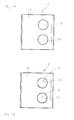
- - ausschnittsweise und schematisch - einen Bereich der ersten Profilwandung des rahmenseitigen Hohlprofils mit eingebrachten Lochungen vor einer ersten Anbringung eines Bandlappens sowie
- Fig. 29
- - wiederum ausschnittsweise und schematisch - denselben Bereich des rahmenseitigen Hohlprofils, nachdem ein Bandlappen angebracht worden ist.
- Das in
Fig. 1 dargestellte Ausführungsbeispiel des erfindungsgemäßen Systems umfasst ein Hohlprofil 1, welches aus einem Kunststoffmaterial hergestellt ist und bei dem dargestellten Ausführungsbeispiel Teil eines Rahmens R bildet. - Innerhalb einer Hohlkammer 2 des Hohlprofils 1 ist zur Verstärkung eine Armierung 3 aus einem Metallprofil eingesetzt. Sie wirkt mit den Begrenzungswandungen 5 der Hohlkammern 2 über Fortsätze 4 formschlüssig zusammen.
- Mit Hilfe eines Bandes 6 ist an dem Rahmen R ein Flügel F um eine Scharnierachse S scharniergelenkig befestigt. Auch der Flügel F umfasst ein Hohlprofil 7, welches wiederum mit Hilfe einer aus einem Metallwerkstoff bestehenden Armierung 8 verstärkt ist.
- Das Band 6 ist - wie in
Fig. 2 und 3 erkennbar ist - als sogenanntes dreiteiliges Band ausgebildet. Es umfasst zwei in Richtung der Scharnierachse S voneinander beabstandete Rahmenbandlappen 9, 9', in deren Abstandsraum ein Flügelbandlappen 10 eingreift. Die Rahmen- und Flügelbandlappen 9, 9'; 10 sind mit Hilfe von zwei Bandbolzenteilen 11, 11', die in Bohrungen 25, 25', 25" der Bandlappen eingreifen, um die Scharnierachse S verschwenkbar miteinander verbunden. Die Bandbolzenteile 11, 11' weisen in dem Bereich, in dem sie in die Rahmenbandlappen 9, 9' hineinragen, jeweils eine Ringnut 12, 12' auf, in welche jeweils zum Zwecke der Fixierung eine in eine Gewindebohrung eingedrehte Stiftschraube 13, 13' eingreift. Der Flügelbandlappen 10 ist mit mindestens einer Lagerbuchse 14 versehen, mit welcher die in den Flügelbandlappen 10 hineinragenden Bereiche der Bandbolzenteile 11, 11' gleitend zusammenwirken, so dass der Flügelbandlappen 10 reibungsarm um die Scharnierachse S verschwenkbar ist. - Der Flügelbandlappen 10 umfasst einen Befestigungsschenkel 15, der zum Eingriff in den zwischen dem Rahmen und dem Flügel gebildeten Falzbereich 16 ausgebildet ist. Seine Form ist an die Gestalt der dem Falzbereich 16 zugewandten Seite 17 des Hohlprofils 7 angepasst, derart, dass der Befestigungsschenkel einen möglichst geringen Platzbedarf aufweist und möglichst flächig an einem Teil der Seite 17 anliegt.
- Bei dem in
Fig. 1 dargestellten Ausführungsbeispiel des Rahmens R weist dessen Hohlprofil 7 an der Seite 17 eine Längsnut 18 auf, in die ein Montage- und Justierstück 19 mit Hilfe von zwei selbstbohrenden Befestigungsschrauben 20 befestigt ist. Sie weisen eine Länge auf, die sicherstellt, dass sie in die Armierung 8 eingreifen. Das Montage- und Justierstück 19 ist derart ausgebildet, dass es mit der Seite 17 des Hohlprofils 7 eine Ebene bildet, die eine Anlagefläche für den Befestigungsschenkel 15 bildet. An dem Montage- und Justierstück 19 ragen von dieser Anlagefläche zwei Fortsätze 21, 21' zum Falzbereich 16 hin. Die einander zugewandten Seiten der Fortsätze 21, 21' sind um einen Betrag voneinander beabstandet, der um eine Justierlänge größer als die Ausdehnung des Befestigungsschenkels 15 ist, mit welcher er in den Raum zwischen den Fortsätzen 21, 21' eingreift. - Die Fortsätze 21, 21' weisen Gewindebohrungen auf, in welche Justierschrauben 22, 22' eingedreht sind und mit ihren einander zugewandten Stirnseiten gegen den Befestigungsschenkel 15 anliegen und diesen zwischen sich einklemmen.
- Der Befestigungsschenkel 15 ist an dem Montage- und Justierstück 19 mit Hilfe von Montageschrauben 23 befestigt, die in hierfür vorgesehene Gewindebohrungen in dem Montage- und Justierstück eingedreht sind und den Befestigungsschenkel 15 in Langlöchern 24 durchsetzen, damit der Befestigungsschenkel 15 und damit der gesamte Flügelbandlappen 10 relativ zum Montage- und Justierstück 19 nach Lösen der Montageschrauben 23 durch Betätigung der Justierschrauben 22, 22' in der zur Scharnierachse S parallelen Richtung X verlagert werden kann.
- Um den Befestigungsschenkel 15 und damit den Flügelbandlappen 10 auch in der zur Richtung X senkrechten Richtung Y verlagern zu können, umfasst das System Unterlegplatten 26 unterschiedlicher Dicke, die wahlweise zwischen den Befestigungsschenkeln 15 und die von dem Hohlprofil 7 und dem Montage- und Justierstück 19 gebildete Anlagefläche nach vorherigem Lösen der Montageschrauben 23 und Abheben des Befestigungsschenkels 15 eingebracht werden können.
- Um die Befestigung des Flügelbandlappens 10 an dem Hohlprofil 7 zu verbessern, ist eine weitere Montageschraube 27 vorgesehen. Sie durchsetzt den Befestigungsschenkel 15 in einem entsprechend den Langlöchern 24 ausgerichteten Langloch 28, welches an einer Stelle des Befestigungsschenkels 15 vorgesehen ist, die ein Eindrehen der Montageschraube 27 in das Hohlprofil 7 nahe seiner Vorderseite 28, die die Sichtseite bildet, erlaubt. Hierdurch wird in Tiefenrichtung Z des Profils ein möglichst großer Abstand zwischen den Befestigungsschrauben 20 und der Montageschraube 27 erzielt, wodurch die Befestigung des Flügelbandlappens 10 gegen Verwindungen oder ein Abheben gegenüber der Vorderseite 28 optimiert wird.
- Das rahmenseitige Hohlprofil 1 weist zwei in einem Winkel ϕ zueinander stehende erste und zweite Profilwandungen 29, 30 auf, die erste und zweite Anlageflächen 31, 32 bilden. Der Winkel ϕ beträgt in dem dargestellten Ausführungsbeispiel 90°. Die erste Anlagefläche 31 bildet zugleich die Vorderseite des Hohlprofils 1, die im geschlossenen Zustand des Flügels F etwa parallel zur Vorderseite 28 verläuft und ebenfalls die Sichtseite bildet.
- Die Ausgestaltung und Funktion der Rahmenbandlappen 9, 9' und des Hohlprofils 1 soll nachfolgend lediglich am Beispiel eines der beiden Rahmenbandlappen 9, 9', nämlich lediglich an dem Rahmenbandlappen 9 erläutert werden.
- Wie insbesondere in
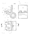
Fig. 4 bis 6 erkennbar ist, die das inFig. 1 bis 3 dargestellte Ausführungsbeispiel des Rahmenbandlappens 9 in Einzeldarstellungen wiedergeben, umfasst der Bandlappen eine erste Gegenanlagefläche 33 und eine zweite Gegenanlagefläche 34. Die erste Gegenanlagefläche 33 wird von einem ersten Schenkel 35, die zweite Gegenanlagefläche 34 von einem zweiten Schenkel 36 gebildet. Die ersten und zweiten Gegenanlageflächen 33, 34 sind in demselben Winkel ϕ zueinander angeordnet wie die ersten und zweiten Anlageflächen 31, 32. Er beträgt - wie bereits weiter oben ausgeführt - bei dem hier dargestellten Ausführungsbeispiel 90°. - Von der ersten Gegenanlagefläche 33 erstrecken sich zwei Vorsprünge 37, 37', die in einer zur Scharnierachse S parallelen Richtung voneinander beabstandet einstückig mit dem ersten Schenkel 35 des Rahmenbandlappens 9 verbunden sind.
- Beide Vorsprünge 37, 37' sind identisch ausgebildet. Sie erstrecken sich jeweils durch eine in der ersten Profilwandung 29 vorgesehene Lochung, von denen in
Fig. 1 lediglich die obere Lochung 38 erkennbar ist, in das Innere des Hohlprofils 1 und hintergreifen die der ersten Anlagefläche 31 gegenüberliegende Innenfläche 39 der ersten Profilwandung 29. Wie insbesondere inFig. 4 und 5 erkennbar ist, sind die Vorsprünge 37, 37' etwa hakenförmig ausgebildet. Ihre Hakenflächen 40 liegen an der Innenfläche 39 zumindest teilweise an. - Die hakenförmigen Vorsprünge umfassen jeweils einen die zugehörige Lochung 38 durchgreifenden Durchgriffsschenkel 41. Er weist einen viereckigen Querschnitt Q auf, die Lochung 38 eine runde Form. Wie in den
Fig. 28 und 29 symbolisiert sind der Querschnitt Q und die Form der Lochung 38 derart bemessen, dass der Querschnitt Q gegenüber der Lochung 38 ein geringfügiges Übermaß aufweist. Das heißt die Ecken des Querschnitts Q liegen geringfügig außerhalb des Randes der Lochung, so dass der Lochungsrand beim Einsetzen des jeweiligen Vorsprungs 37, 37' im Bereich der Positionen der Ecken verformt wird. Aufgrund dieser Maßnahme ist ein spielfreier Sitz des Vorsprungs in der Lochung sichergestellt. - Grundsätzlich ist es möglich, auch andere Lochungsformen und andere Querschnitte des Durchgriffsschenkels zu wählen. Bei der zuvor beschriebenen Auswahl weisen die Vorsprünge jeweils eine Schrägfläche 42 auf, die zur ersten Gegenanlagefläche 33 etwa um 45° geneigt ist. Diese Schrägfläche ermöglicht es, den Rahmenbandlappen 9 zur Montage an dem Hohlprofil zunächst in einem schrägen Winkel zwischen der ersten Anlagefläche 31 und der ersten Gegenanlagefläche 33 so aufzusetzen, dass die Vorsprünge 37, 37' mit ihren freien Endbereichen in die jeweils zugehörige Lochung 38 eingreifen. Zur weiteren Montage wird dann der Rahmenbandlappen 9 so verschwenkt, dass die erste Gegenanlagefläche 33 zur ersten Anlagefläche 31 hin bewegt wird, wobei die Vorsprünge 37, 37' weiter in das Innere des Hohlprofils 1 hineinverlagert werden und sich die Ecken des Durchgriffsschenkels 41 in den Rand der Lochung 38 "einformen".
- Für einen spielfreien Sitz ist es erforderlich, dass der senkrechte Abstand B zwischen der Hakenfläche 40 und der ersten Gegenanlagefläche 33 der Dicke D der ersten Profilwandung 29 entspricht.
- Um eine selbsttätige Anpassung an gewisse Fertigungstoleranzen sowohl hinsichtlich der Dicke D, als auch hinsichtlich des Abstandes B bewerkstelligen zu können, sind bei dem in
Fig. 7 bis 9 dargestellten Ausführungsbeispiel die Vorsprünge 37, 37' derart ausgebildet, dass der Abstand zwischen der Hakenfläche 40 und der ersten Gegenanlagefläche 33 zur offenen Seite des Hakens hin abnimmt. Eine einen Radius aufweisende Einkerbung 43 am zur geschlossenen Seite weisenden Ende der Hakenfläche 40 bewirkt, dass sich die Bereiche der Vorsprünge 37, 37', die die Hakenfläche 40 bilden, elastisch verformen können, ohne dass es am Ende der Hakenfläche 40 zu übermäßigen Spannungsspitzen, die zu einer Rissbildung führen können, kommt. Mit dieser Ausgestaltung ist der Rahmenbandlappen zum Ausgleich von Toleranzen geeignet, die die Differenz zwischen den Abständen B1 und B2 nicht übersteigen. - Bei dem in
Fig. 10 bis 12 dargestellten, weiteren Ausführungsbeispiel sind die Vorsprünge 37, 37' derart ausgebildet, dass jeweils der Abstand zwischen der Hakenfläche 40 und der Gegenanlagefläche 33 zur offenen Seite des Hakens zunimmt. Wiederum ist diese Ausführungsform geeignet, Toleranzen von maximal der Differenz zwischen den Abständen B1 und B2 zu kompensieren, da das vollständige Einbringen der Vorsprünge 37, 37' dazu führt, dass sich der Haken im Umfang der Toleranz zumindest teilweise in die erste Profilwandung 29 "eingräbt". - Um den Rahmenbandlappen 9 in seiner Position, in welcher die Hakenfläche 40 die Innenfläche 39 hintergreift und die erste Gegenanlagefläche 33 an der ersten Anlagefläche 31 der ersten Profilwandung 29 anliegt, zu fixieren, sind Befestigungsmittel 44 vorgesehen, mit welchen die zweite Gegenanlagefläche 34 relativ zur zweiten Anlagefläche 32 der zweiten Profilwandung 30 fixierbar bzw. im fest montierten Zustand des Rahmenbandlappens fixiert ist.
- Bei der in
Fig. 1 bis 3 dargestellten Ausführungsform umfassen diese Befestigungsmittel 44 Befestigungsschrauben 45, die als selbstbohrende Schrauben ausgebildet sind. Zu deren Durchgriff sind in den zweiten Schenkeln 36 bei den inFig. 7 bis 9 sowie 10 bis 12 dargestellten Ausführungsbeispielen Bohrungen 46 vorgesehen. Sie sind derart positioniert, dass die Befestigungsschrauben 45 auch in die Armierung 3 eingreifen, um so die Belastbarkeit der Verschraubung zu erhöhen. - Derartige Bohrungen 46 sind bei dem in
Fig. 4 bis 6 dargestellten Ausführungsbeispiel des Rahmenbandlappens 9 nicht vorgesehen. Bei diesem Ausführungsbeispiel finden anders geartete Befestigungsmittel Verwendung. Beispielsweise könnte die zweite Gegenanlagefläche 34 mit der zweiten Anlagefläche 32 verklebt werden, indem vor dem vollständigen Einschwenken auf die Gegenanlagefläche und/oder die Anlagefläche zum Verbinden der entsprechenden Materialpaarung geeigneter Klebstoff aufgetragen wird. - Oder es wird - wie in
Fig. 13 und 14 dargestellt - an dem Hohlprofil 1 ein Rastvorsprung 47 vorgesehen, der zusammen mit dem zweiten Schenkel 36 eine Rastvorrichtung 48 bildet, wenn der zweite Schenkel 36 in den Bereich zwischen dem Rastvorsprung 47 und der zweiten Anlagefläche 32 eingreift. - Um ein Einbringen des Schenkels 36 in diesen Bereich unter elastischer Verformung des Rastvorsprungs 47 und/oder des Hohlprofils 1 zu erleichtern, weist der Rastvorsprung 47 eine Schrägfläche 49 auf, an welcher der Rand 50, der mit einem Radius versehen ist, des zweiten Schenkels abgleiten kann.
- Zur Fixierung des Rahmenbandlappens 9 in seiner in
Fig. 13 und 14 dargestellten, montierten Position können auch anders gestaltete Rastvorrichtungen Verwendung finden. Beispielsweise könnte, wie inFig. 15 bis 27 dargestellt ist, mindestens ein sich von der zweiten Gegenanlagefläche 34 erstreckender Rasthaken 52 mit einer Rastfläche 55 vorgesehen sein, welcher sich in eine zuvor in die zweite Profilwandung 30 und gegebenenfalls auch in die Armierung 3 eingebrachte Lochung 51, 51' erstreckt und mit von Innenflächen 54, 54' der zweiten Profilwandung 30 oder der Armierung 3 gebildeten Rastflächen 53, 53' verrastet. Bei dem Ausführungsbeispiel gemäß derFig. 15 bis 19 sind zwei in Richtung parallel zur Scharnierachse S getrennte Rasthaken 52 vorgesehen. Hingegen ist der Rasthaken 52' bei dem Ausführungsbeispiel gemäß derFig. 20 bis 27 als sich über die gesamte Länge erstreckender Einzelhaken ausgebildet, und die Lochung 51' dementsprechend langlochförmig. - Der Montagevorgang des Bandlappens 9 an einem Hohlprofil 1 erfolgt bei sämtlichen Ausführungsbeispielen in der in
Fig. 24 bis 27 dargestellten Weise. Es wird nämlich zunächst der Bandlappen derart angesetzt, dass seine Vorsprünge 37, 37' in die zugehörigen Lochungen 38 hineinragen. Anschließend wird der Bandlappen 9 - bei der inFig. 24 bis Fig. 27 dargestellten Anordnung - im Uhrzeigersinn soweit verschwenkt, bis der zweite Schenkel 36 an der zweiten Profilwandung 30 vollständig anliegt (s.Fig. 26 ). Bei der hier dargestellten Ausführungsform ist der Bandlappen 9 mit Hilfe des Rasthakens 52' bereits selbsttätig arretiert. Dies gilt auch für die beiden weiteren Ausführungsformen 13 und 14 sowie 15 bis 19, bei welchen die Befestigungsmittel 44 stets Rastvorrichtungen umfassen. - Für den Fall, dass die Befestigungsmittel 44 Schrauben, Nieten oder Mittel zur Bewirkung einer stoffschlüssigen Verbindung umfassen, so müssen diese in der in
Fig. 26 dargestellten Position erst eingebracht bzw. aktiviert werden. - Bei den in der Zeichnung dargestellten Ausführungsbeispielen bildet das erfindungsgemäße System stets einen Teil des Rahmens. Es ist jedoch ebenfalls möglich und wird von der Erfindung vollumfänglich erfasst, das erfindungsgemäße System als Teil des Flügels einzusetzen. Auch können sowohl flügel-, als auch rahmenseitig erfindungsgemäße Systeme Verwendung finden. Darüber hinaus ist die Erfindung nicht auf dreiteilige Bänder, wie in den Ausführungsbeispielen dargestellt, beschränkt. Sondern es lassen sich auch Systeme mit zwei- oder mehrteiligen Bändern in entsprechender Weise ausbilden.
-
- 1
- Hohlprofil
- 2
- Hohlkammern
- 3
- Armierung
- 4
- Fortsätze
- 5
- Begrenzungswandungen
- 6
- Band
- 7
- Hohlprofil
- 8
- Armierung
- 9, 9'
- Rahmenbandlappen
- 10
- Flügelbandlappen
- 11, 11'
- Bandbolzenteile
- 12, 12'
- Ringnut
- 13, 13'
- Stiftschraube
- 14
- Lagerbuchse
- 15
- Befestigungsschenkel
- 16
- Falzbereich
- 17
- Seite
- 18
- Längsnut
- 19
- Montage- und Justierstück
- 20
- Befestigungsschrauben
- 21, 21'
- Fortsätze
- 22, 22'
- Justierschrauben
- 23
- Montageschrauben
- 24
- Langlöcher
- 25, 25', 25"
- Bohrungen
- 26
- Unterlegplatten
- 27
- Montageschraube
- 28
- Vorderseite
- 29
- erste Profilwandung
- 30
- zweite Profilwandung
- 31
- erste Anlagefläche
- 32
- zweite Anlagefläche
- 33
- erste Gegenanlagefläche
- 34
- zweite Gegenanlagefläche
- 35
- erster Schenkel
- 36
- zweiter Schenkel
- 37, 37'
- Vorsprünge
- 38
- Lochung
- 39
- Innenfläche
- 40
- Hakenflächen
- 41
- Durchgriffsschenkel
- 42
- Schrägfläche
- 43
- Einkerbung
- 44
- Befestigungsmittel
- 45
- Befestigungsschrauben
- 46
- Bohrungen
- 47
- Rastleiste
- 48
- Rastvorrichtung
- 49
- Schrägfläche
- 50
- Rand
- 51,51'
- Lochung
- 52, 52'
- Rasthaken
- 53, 53'
- Rastfläche
- 54, 54'
- Innenfläche
- 55, 55'
- Rastfläche
- B, B1, B2
- Abstände
- F
- Flügel
- Q
- Querschnitt
- R
- Rahmen
- S
- Scharnierachse
- X, Y, Z
- Richtung
- ϕ
- Winkel
Claims (15)
- System, umfassend:- ein Hohlprofil (1) mit in einem Winkel (ϕ) zueinander stehenden ersten und zweiten Profilwandungen (29, 30) mit ersten und zweiten Anlageflächen (31, 32),- einen Bandlappen (9) eines Bandes (6), der an den Anlageflächen (31, 32) mittelbar oder unmittelbar anliegende erste und zweite Gegenanlageflächen (33, 34) aufweist, wobei sich von der ersten Gegenanlagefläche (33) mindestens ein Vorsprung (37, 37') erstreckt, der durch eine in der ersten Profilwandung (29) vorgesehene Lochung (38) in das Innere des Hohlprofils (1) eingreift und die der ersten Anlagefläche (31) gegenüberliegende Innenfläche (39) der mindestens einen ersten Profilwandung (29) hintergreift,- und Befestigungsmittel (44), mittels welchen die zweite Gegenanlagefläche (34) hinsichtlich der zweiten Anlagefläche (32) fixierbar ist.
- System nach Anspruch 1, dadurch gekennzeichnet, dass der mindestens eine Vorsprung (37, 37') etwa hakenförmig ausgebildet ist.
- System nach Anspruch 2, dadurch gekennzeichnet, dass der Vorsprung (37, 37') eine der Innenfläche (39) zugewandte Hakenfläche (40) aufweist, die zumindest teilweise an der Innenfläche (39) anliegt.
- System nach Anspruch 3, dadurch gekennzeichnet, dass der Vorsprung (37, 37') derart ausgebildet ist, dass die Hakenfläche (40) nicht parallel zur ersten Gegenanlagefläche (33) verläuft.
- System nach Anspruch 4, dadurch gekennzeichnet, dass der Vorsprung (37, 37') derart ausgebildet ist, dass der Abstand zwischen der Hakenfläche (40) und der ersten Gegenanlagefläche (33) zur offenen Seite des Hakens hin zunimmt.
- System nach Anspruch 4, dadurch gekennzeichnet, dass der Vorsprung (37, 37') derart ausgebildet ist, dass der Abstand zwischen der Hakenfläche (40) und der ersten Gegenanlagefläche (33) zur offenen Seite des Hakens hin abnimmt.
- System nach einem der Ansprüche 2 bis 6, dadurch gekennzeichnet, dass der hakenförmige Vorsprung (37, 37') einen die Lochung (38) durchgreifenden Durchgriffsschenkel (41) umfasst, der einen mehreckigen Querschnitt aufweist, dass die Lochung (38) eine von dem Querschnitt abweichende Form aufweist, und dass der Querschnitt gegenüber der Lochung ein Übermaß aufweist, so dass der Durchgriffsschenkel (41) den Lochungsrand verformt.
- System nach Anspruch 7, dadurch gekennzeichnet, dass der Durchgriffsschenkel (41) einen viereckigen Querschnitt und die Lochung (38) eine runde Form aufweist.
- System nach einem der Ansprüche 1 bis 4, dadurch gekennzeichnet, dass die Befestigungsmittel (44) mindestens eine Schraube (45), mindestens eine Niet, mindestens eine Rastvorrichtung (48) und/oder Mittel zur stoffschlüssigen Verbindung umfassen.
- System nach Anspruch 9, dadurch gekennzeichnet, dass die Rastvorrichtung (48) einen an dem Hohlprofil (1) angebrachten, vorzugsweise angeformten Rastvorsprung (47) umfasst, der einen die zweite Gegenanlagefläche (34) bildenden zweiten Schenkel (36) des Bandlappens (9) zumindest teilweise hintergreift.
- System nach Anspruch 10, dadurch gekennzeichnet, dass der Rastvorsprung (47) und der zweite Schenkel (36) derart ausgebildet sind, dass der zweite Schenkel (36) unter elastischer Verformung seiner selbst und/oder des Rastvorsprungs (47) in die den Rastvorsprung (47) hintergreifende Position verlagerbar ist.
- System nach Anspruch 9, dadurch gekennzeichnet, dass die Rastvorrichtung (48) eine in der zweiten Profilwandung (30) vorgesehene Lochung (51) sowie einen sich von dem zweiten Schenkel (36) erstreckenden Rasthaken (52) umfasst der eine Rastfläche (53, 53') des Hohlprofils (1) hintergreift.
- System nach Anspruch 12, dadurch gekennzeichnet, dass die Rastfläche (53) von der der zweiten Anlagefläche (32) gegenüberliegenden Innenfläche (54) der zweiten Profilwandung (30) gebildet ist.
- System nach Anspruch 12, dadurch gekennzeichnet, dass in der Armierung (3) eine Lochung (51') vorgesehen ist, und dass die Rastfläche (53') von einer von der zweien Anlagefläche (32) fort weisenden Innenfläche (54') gebildet ist.
- System nach einem der Ansprüche 1 bis 11, dadurch gekennzeichnet, dass der Bandlappen (9) aus einem Metallwerkstoff, vorzugsweise aus einem A-luminiumstranggussprofil und/oder das Hohlprofil (1) aus einem Kunststoffwerkstoff, vorzugsweise mit eingesetzter Metallarmierung (3), ausgebildet ist.
Priority Applications (1)
| Application Number | Priority Date | Filing Date | Title |
|---|---|---|---|
| PL13152021T PL2617921T3 (pl) | 2012-01-23 | 2013-01-21 | Układ zawierający profil wydrążony i skrzydełko zawiasu |
Applications Claiming Priority (1)
| Application Number | Priority Date | Filing Date | Title |
|---|---|---|---|
| DE202012100233U DE202012100233U1 (de) | 2012-01-23 | 2012-01-23 | System, umfassend ein Hohlprofil und einen Bandlappen eines Bandes, sowie Bandlappen |
Publications (3)
| Publication Number | Publication Date |
|---|---|
| EP2617921A2 true EP2617921A2 (de) | 2013-07-24 |
| EP2617921A3 EP2617921A3 (de) | 2017-08-23 |
| EP2617921B1 EP2617921B1 (de) | 2021-08-18 |
Family
ID=47603393
Family Applications (1)
| Application Number | Title | Priority Date | Filing Date |
|---|---|---|---|
| EP13152021.5A Active EP2617921B1 (de) | 2012-01-23 | 2013-01-21 | System umfassend ein Hohlprofil und einen Bandlappen eines Bandes |
Country Status (3)
| Country | Link |
|---|---|
| EP (1) | EP2617921B1 (de) |
| DE (1) | DE202012100233U1 (de) |
| PL (1) | PL2617921T3 (de) |
Cited By (3)
| Publication number | Priority date | Publication date | Assignee | Title |
|---|---|---|---|---|
| DE202013104273U1 (de) | 2013-09-18 | 2015-01-09 | Dr. Hahn Gmbh & Co. Kg | System, umfassend ein Hohlprofil und einen Bandlappen eines Bandes, Bandlappen dieses Systems sowie Justierstück dieses Bandlappens |
| CN109515528A (zh) * | 2018-12-29 | 2019-03-26 | 杭州华聚复合材料有限公司 | 新能源物流车、车厢及其裙边总成 |
| WO2022055376A1 (en) | 2020-09-11 | 2022-03-17 | "Wala" Spółka Z Ograniczoną Odpowiedzialnością | Hinge arrangement for plastic profiles |
Families Citing this family (2)
| Publication number | Priority date | Publication date | Assignee | Title |
|---|---|---|---|---|
| DE202014100431U1 (de) | 2014-01-31 | 2014-02-12 | Haps Gmbh + Co. Kg | Bandanordnung mit Justiermitteln |
| DE202014100430U1 (de) | 2014-01-31 | 2014-02-12 | Haps Gmbh + Co. Kg | Bandanordnung |
Citations (1)
| Publication number | Priority date | Publication date | Assignee | Title |
|---|---|---|---|---|
| DE20005202U1 (de) | 2000-03-18 | 2001-07-26 | Dr. Hahn GmbH & Co. KG, 41189 Mönchengladbach | Bandanordnung für Türen, Fenster u.dgl. |
Family Cites Families (3)
| Publication number | Priority date | Publication date | Assignee | Title |
|---|---|---|---|---|
| US5180250A (en) * | 1989-08-08 | 1993-01-19 | Alprogetti S.R.L. | Self-locking coupling structure for connecting accessories to profiled elements |
| DE19961980A1 (de) * | 1999-12-22 | 2001-07-05 | Gerd Laemmermann | Befestigungssystem für Fenster und Türen |
| CH696853A5 (de) * | 2003-12-09 | 2007-12-31 | Harald Sitter | Scharnier, insbesondere für Türen. |
-
2012
- 2012-01-23 DE DE202012100233U patent/DE202012100233U1/de not_active Expired - Lifetime
-
2013
- 2013-01-21 EP EP13152021.5A patent/EP2617921B1/de active Active
- 2013-01-21 PL PL13152021T patent/PL2617921T3/pl unknown
Patent Citations (1)
| Publication number | Priority date | Publication date | Assignee | Title |
|---|---|---|---|---|
| DE20005202U1 (de) | 2000-03-18 | 2001-07-26 | Dr. Hahn GmbH & Co. KG, 41189 Mönchengladbach | Bandanordnung für Türen, Fenster u.dgl. |
Cited By (4)
| Publication number | Priority date | Publication date | Assignee | Title |
|---|---|---|---|---|
| DE202013104273U1 (de) | 2013-09-18 | 2015-01-09 | Dr. Hahn Gmbh & Co. Kg | System, umfassend ein Hohlprofil und einen Bandlappen eines Bandes, Bandlappen dieses Systems sowie Justierstück dieses Bandlappens |
| CN109515528A (zh) * | 2018-12-29 | 2019-03-26 | 杭州华聚复合材料有限公司 | 新能源物流车、车厢及其裙边总成 |
| CN109515528B (zh) * | 2018-12-29 | 2024-06-18 | 杭州华聚复合材料有限公司 | 新能源物流车、车厢及其裙边总成 |
| WO2022055376A1 (en) | 2020-09-11 | 2022-03-17 | "Wala" Spółka Z Ograniczoną Odpowiedzialnością | Hinge arrangement for plastic profiles |
Also Published As
| Publication number | Publication date |
|---|---|
| DE202012100233U1 (de) | 2013-04-24 |
| PL2617921T3 (pl) | 2022-01-03 |
| EP2617921A3 (de) | 2017-08-23 |
| EP2617921B1 (de) | 2021-08-18 |
Similar Documents
| Publication | Publication Date | Title |
|---|---|---|
| EP3613931B1 (de) | Baugruppe eines bandes zur um eine scharnierachse scharnierbeweglichen verbindung eines flügels an einem rahmen | |
| EP2617921B1 (de) | System umfassend ein Hohlprofil und einen Bandlappen eines Bandes | |
| EP2118416A1 (de) | Vorrichtung mit einem montageeinsatz zur befestigung von beschlagteilen an hohlprofilen sowie verfahren zur anbringung des montageeinsatzes an dem hohlprofil | |
| EP2345786B1 (de) | Türband für Aluminiumtüren | |
| EP3425155B1 (de) | Klemmschutzeinrichtung für eine tür | |
| EP4015749A1 (de) | Befestigungseinrichtung zur befestigung eines beschlagteils an einem eine nut aufweisenden rahmen einer gebäudeverschlusseinrichtung, gebäudeverschlusseinrichtung sowie verfahren zum befestigen eines beschlagteils an einem rahmen einer gebäudeverschlusseinrichtung | |
| EP3814593B1 (de) | Baugruppe eines bandes zur um eine scharnierachse scharniergelenkigen verbindung eines flügels an einem rahmen sowie band mit dieser baugruppe | |
| EP2788210B1 (de) | Trägerbauteil für einen kraftfahrzeug-fensterheber mit versteifungsstruktur | |
| EP1132560A2 (de) | Scharnier, sowie Verfahren zur Höhenverstellung eines Scharniers | |
| DE202008016071U1 (de) | Band zur scharniergelenkigen Verbindung eines Flügels an einem Rahmen | |
| DE202015100200U1 (de) | Bandlappenanordnung eines Bandes | |
| EP2514892B1 (de) | System zur Befestigung eines Beschlagteils | |
| EP1915498B1 (de) | Profilbandsystem | |
| EP4191013A1 (de) | Dichtungseinheit für eine schiebetür | |
| DE202007006349U1 (de) | Bandanordnung | |
| DE202007015154U1 (de) | System zur Befestigung eines Beschlagteils an einem Hohlprofil | |
| WO2007042132A1 (de) | Befestigungsvorrichtung für ein beschlagteil | |
| EP2947247B1 (de) | Wohndachfenster mit verstellbarem scharnier | |
| DE29907394U1 (de) | Bandhälfte eines Bandes für Fenster, Türen o.dgl. | |
| EP0945574B1 (de) | Band für Türen, Fenster oder dergleichen | |
| DE202006001574U1 (de) | Bandanordnung zur scharniergelenkigen Verbindung eines Flügels einer Tür, eines Fensters o.dgl., an einem Rahmen | |
| EP2730732A2 (de) | Band für Türen, Fenster oder dergleichen | |
| DE102022200962A1 (de) | Gebäudeverschlusseinrichtung sowie Verfahren zum Montieren einer Gebäudeverschlusseinrichtung | |
| DE202013104273U1 (de) | System, umfassend ein Hohlprofil und einen Bandlappen eines Bandes, Bandlappen dieses Systems sowie Justierstück dieses Bandlappens | |
| DE102007024082B3 (de) | Vorrichtung und Verfahren zur Befestigung von Beschlagteilen an Montagewandungen von Einkammerprofilen |
Legal Events
| Date | Code | Title | Description |
|---|---|---|---|
| PUAI | Public reference made under article 153(3) epc to a published international application that has entered the european phase |
Free format text: ORIGINAL CODE: 0009012 |
|
| AK | Designated contracting states |
Kind code of ref document: A2 Designated state(s): AL AT BE BG CH CY CZ DE DK EE ES FI FR GB GR HR HU IE IS IT LI LT LU LV MC MK MT NL NO PL PT RO RS SE SI SK SM TR |
|
| AX | Request for extension of the european patent |
Extension state: BA ME |
|
| PUAL | Search report despatched |
Free format text: ORIGINAL CODE: 0009013 |
|
| AK | Designated contracting states |
Kind code of ref document: A3 Designated state(s): AL AT BE BG CH CY CZ DE DK EE ES FI FR GB GR HR HU IE IS IT LI LT LU LV MC MK MT NL NO PL PT RO RS SE SI SK SM TR |
|
| AX | Request for extension of the european patent |
Extension state: BA ME |
|
| RIC1 | Information provided on ipc code assigned before grant |
Ipc: E05D 5/02 20060101AFI20170720BHEP |
|
| STAA | Information on the status of an ep patent application or granted ep patent |
Free format text: STATUS: REQUEST FOR EXAMINATION WAS MADE |
|
| 17P | Request for examination filed |
Effective date: 20171106 |
|
| RBV | Designated contracting states (corrected) |
Designated state(s): AL AT BE BG CH CY CZ DE DK EE ES FI FR GB GR HR HU IE IS IT LI LT LU LV MC MK MT NL NO PL PT RO RS SE SI SK SM TR |
|
| GRAP | Despatch of communication of intention to grant a patent |
Free format text: ORIGINAL CODE: EPIDOSNIGR1 |
|
| STAA | Information on the status of an ep patent application or granted ep patent |
Free format text: STATUS: GRANT OF PATENT IS INTENDED |
|
| INTG | Intention to grant announced |
Effective date: 20210409 |
|
| GRAS | Grant fee paid |
Free format text: ORIGINAL CODE: EPIDOSNIGR3 |
|
| GRAA | (expected) grant |
Free format text: ORIGINAL CODE: 0009210 |
|
| STAA | Information on the status of an ep patent application or granted ep patent |
Free format text: STATUS: THE PATENT HAS BEEN GRANTED |
|
| AK | Designated contracting states |
Kind code of ref document: B1 Designated state(s): AL AT BE BG CH CY CZ DE DK EE ES FI FR GB GR HR HU IE IS IT LI LT LU LV MC MK MT NL NO PL PT RO RS SE SI SK SM TR |
|
| REG | Reference to a national code |
Ref country code: GB Ref legal event code: FG4D Free format text: NOT ENGLISH |
|
| REG | Reference to a national code |
Ref country code: CH Ref legal event code: EP |
|
| REG | Reference to a national code |
Ref country code: DE Ref legal event code: R096 Ref document number: 502013015882 Country of ref document: DE |
|
| REG | Reference to a national code |
Ref country code: IE Ref legal event code: FG4D Free format text: LANGUAGE OF EP DOCUMENT: GERMAN Ref country code: AT Ref legal event code: REF Ref document number: 1421794 Country of ref document: AT Kind code of ref document: T Effective date: 20210915 |
|
| REG | Reference to a national code |
Ref country code: LT Ref legal event code: MG9D |
|
| REG | Reference to a national code |
Ref country code: NL Ref legal event code: MP Effective date: 20210818 |
|
| PG25 | Lapsed in a contracting state [announced via postgrant information from national office to epo] |
Ref country code: ES Free format text: LAPSE BECAUSE OF FAILURE TO SUBMIT A TRANSLATION OF THE DESCRIPTION OR TO PAY THE FEE WITHIN THE PRESCRIBED TIME-LIMIT Effective date: 20210818 Ref country code: FI Free format text: LAPSE BECAUSE OF FAILURE TO SUBMIT A TRANSLATION OF THE DESCRIPTION OR TO PAY THE FEE WITHIN THE PRESCRIBED TIME-LIMIT Effective date: 20210818 Ref country code: RS Free format text: LAPSE BECAUSE OF FAILURE TO SUBMIT A TRANSLATION OF THE DESCRIPTION OR TO PAY THE FEE WITHIN THE PRESCRIBED TIME-LIMIT Effective date: 20210818 Ref country code: NO Free format text: LAPSE BECAUSE OF FAILURE TO SUBMIT A TRANSLATION OF THE DESCRIPTION OR TO PAY THE FEE WITHIN THE PRESCRIBED TIME-LIMIT Effective date: 20211118 Ref country code: PT Free format text: LAPSE BECAUSE OF FAILURE TO SUBMIT A TRANSLATION OF THE DESCRIPTION OR TO PAY THE FEE WITHIN THE PRESCRIBED TIME-LIMIT Effective date: 20211220 Ref country code: BG Free format text: LAPSE BECAUSE OF FAILURE TO SUBMIT A TRANSLATION OF THE DESCRIPTION OR TO PAY THE FEE WITHIN THE PRESCRIBED TIME-LIMIT Effective date: 20211118 Ref country code: LT Free format text: LAPSE BECAUSE OF FAILURE TO SUBMIT A TRANSLATION OF THE DESCRIPTION OR TO PAY THE FEE WITHIN THE PRESCRIBED TIME-LIMIT Effective date: 20210818 Ref country code: SE Free format text: LAPSE BECAUSE OF FAILURE TO SUBMIT A TRANSLATION OF THE DESCRIPTION OR TO PAY THE FEE WITHIN THE PRESCRIBED TIME-LIMIT Effective date: 20210818 Ref country code: HR Free format text: LAPSE BECAUSE OF FAILURE TO SUBMIT A TRANSLATION OF THE DESCRIPTION OR TO PAY THE FEE WITHIN THE PRESCRIBED TIME-LIMIT Effective date: 20210818 |
|
| PG25 | Lapsed in a contracting state [announced via postgrant information from national office to epo] |
Ref country code: LV Free format text: LAPSE BECAUSE OF FAILURE TO SUBMIT A TRANSLATION OF THE DESCRIPTION OR TO PAY THE FEE WITHIN THE PRESCRIBED TIME-LIMIT Effective date: 20210818 Ref country code: GR Free format text: LAPSE BECAUSE OF FAILURE TO SUBMIT A TRANSLATION OF THE DESCRIPTION OR TO PAY THE FEE WITHIN THE PRESCRIBED TIME-LIMIT Effective date: 20211119 |
|
| PG25 | Lapsed in a contracting state [announced via postgrant information from national office to epo] |
Ref country code: NL Free format text: LAPSE BECAUSE OF FAILURE TO SUBMIT A TRANSLATION OF THE DESCRIPTION OR TO PAY THE FEE WITHIN THE PRESCRIBED TIME-LIMIT Effective date: 20210818 |
|
| PG25 | Lapsed in a contracting state [announced via postgrant information from national office to epo] |
Ref country code: DK Free format text: LAPSE BECAUSE OF FAILURE TO SUBMIT A TRANSLATION OF THE DESCRIPTION OR TO PAY THE FEE WITHIN THE PRESCRIBED TIME-LIMIT Effective date: 20210818 |
|
| REG | Reference to a national code |
Ref country code: DE Ref legal event code: R097 Ref document number: 502013015882 Country of ref document: DE |
|
| PG25 | Lapsed in a contracting state [announced via postgrant information from national office to epo] |
Ref country code: SM Free format text: LAPSE BECAUSE OF FAILURE TO SUBMIT A TRANSLATION OF THE DESCRIPTION OR TO PAY THE FEE WITHIN THE PRESCRIBED TIME-LIMIT Effective date: 20210818 Ref country code: SK Free format text: LAPSE BECAUSE OF FAILURE TO SUBMIT A TRANSLATION OF THE DESCRIPTION OR TO PAY THE FEE WITHIN THE PRESCRIBED TIME-LIMIT Effective date: 20210818 Ref country code: RO Free format text: LAPSE BECAUSE OF FAILURE TO SUBMIT A TRANSLATION OF THE DESCRIPTION OR TO PAY THE FEE WITHIN THE PRESCRIBED TIME-LIMIT Effective date: 20210818 Ref country code: EE Free format text: LAPSE BECAUSE OF FAILURE TO SUBMIT A TRANSLATION OF THE DESCRIPTION OR TO PAY THE FEE WITHIN THE PRESCRIBED TIME-LIMIT Effective date: 20210818 Ref country code: CZ Free format text: LAPSE BECAUSE OF FAILURE TO SUBMIT A TRANSLATION OF THE DESCRIPTION OR TO PAY THE FEE WITHIN THE PRESCRIBED TIME-LIMIT Effective date: 20210818 Ref country code: AL Free format text: LAPSE BECAUSE OF FAILURE TO SUBMIT A TRANSLATION OF THE DESCRIPTION OR TO PAY THE FEE WITHIN THE PRESCRIBED TIME-LIMIT Effective date: 20210818 |
|
| PLBE | No opposition filed within time limit |
Free format text: ORIGINAL CODE: 0009261 |
|
| STAA | Information on the status of an ep patent application or granted ep patent |
Free format text: STATUS: NO OPPOSITION FILED WITHIN TIME LIMIT |
|
| 26N | No opposition filed |
Effective date: 20220519 |
|
| PG25 | Lapsed in a contracting state [announced via postgrant information from national office to epo] |
Ref country code: SI Free format text: LAPSE BECAUSE OF FAILURE TO SUBMIT A TRANSLATION OF THE DESCRIPTION OR TO PAY THE FEE WITHIN THE PRESCRIBED TIME-LIMIT Effective date: 20210818 Ref country code: MC Free format text: LAPSE BECAUSE OF FAILURE TO SUBMIT A TRANSLATION OF THE DESCRIPTION OR TO PAY THE FEE WITHIN THE PRESCRIBED TIME-LIMIT Effective date: 20210818 |
|
| REG | Reference to a national code |
Ref country code: CH Ref legal event code: PL |
|
| GBPC | Gb: european patent ceased through non-payment of renewal fee |
Effective date: 20220121 |
|
| PG25 | Lapsed in a contracting state [announced via postgrant information from national office to epo] |
Ref country code: LU Free format text: LAPSE BECAUSE OF NON-PAYMENT OF DUE FEES Effective date: 20220121 Ref country code: GB Free format text: LAPSE BECAUSE OF NON-PAYMENT OF DUE FEES Effective date: 20220121 |
|
| PG25 | Lapsed in a contracting state [announced via postgrant information from national office to epo] |
Ref country code: FR Free format text: LAPSE BECAUSE OF NON-PAYMENT OF DUE FEES Effective date: 20220131 |
|
| PG25 | Lapsed in a contracting state [announced via postgrant information from national office to epo] |
Ref country code: LI Free format text: LAPSE BECAUSE OF NON-PAYMENT OF DUE FEES Effective date: 20220131 Ref country code: CH Free format text: LAPSE BECAUSE OF NON-PAYMENT OF DUE FEES Effective date: 20220131 |
|
| REG | Reference to a national code |
Ref country code: DE Ref legal event code: R082 Ref document number: 502013015882 Country of ref document: DE Representative=s name: PATENTANWAELTE KLUIN DEBELIUS WEBER PARTG MBB, DE |
|
| PG25 | Lapsed in a contracting state [announced via postgrant information from national office to epo] |
Ref country code: IE Free format text: LAPSE BECAUSE OF NON-PAYMENT OF DUE FEES Effective date: 20220121 |
|
| REG | Reference to a national code |
Ref country code: AT Ref legal event code: MM01 Ref document number: 1421794 Country of ref document: AT Kind code of ref document: T Effective date: 20220121 |
|
| PG25 | Lapsed in a contracting state [announced via postgrant information from national office to epo] |
Ref country code: AT Free format text: LAPSE BECAUSE OF NON-PAYMENT OF DUE FEES Effective date: 20220121 |
|
| P01 | Opt-out of the competence of the unified patent court (upc) registered |
Effective date: 20230523 |
|
| PG25 | Lapsed in a contracting state [announced via postgrant information from national office to epo] |
Ref country code: HU Free format text: LAPSE BECAUSE OF FAILURE TO SUBMIT A TRANSLATION OF THE DESCRIPTION OR TO PAY THE FEE WITHIN THE PRESCRIBED TIME-LIMIT; INVALID AB INITIO Effective date: 20130121 |
|
| PG25 | Lapsed in a contracting state [announced via postgrant information from national office to epo] |
Ref country code: MK Free format text: LAPSE BECAUSE OF FAILURE TO SUBMIT A TRANSLATION OF THE DESCRIPTION OR TO PAY THE FEE WITHIN THE PRESCRIBED TIME-LIMIT Effective date: 20210818 Ref country code: CY Free format text: LAPSE BECAUSE OF FAILURE TO SUBMIT A TRANSLATION OF THE DESCRIPTION OR TO PAY THE FEE WITHIN THE PRESCRIBED TIME-LIMIT Effective date: 20210818 |
|
| PG25 | Lapsed in a contracting state [announced via postgrant information from national office to epo] |
Ref country code: MT Free format text: LAPSE BECAUSE OF FAILURE TO SUBMIT A TRANSLATION OF THE DESCRIPTION OR TO PAY THE FEE WITHIN THE PRESCRIBED TIME-LIMIT Effective date: 20210818 |
|
| PG25 | Lapsed in a contracting state [announced via postgrant information from national office to epo] |
Ref country code: TR Free format text: LAPSE BECAUSE OF FAILURE TO SUBMIT A TRANSLATION OF THE DESCRIPTION OR TO PAY THE FEE WITHIN THE PRESCRIBED TIME-LIMIT Effective date: 20210818 |
|
| PGFP | Annual fee paid to national office [announced via postgrant information from national office to epo] |
Ref country code: DE Payment date: 20260131 Year of fee payment: 14 |
|
| PGFP | Annual fee paid to national office [announced via postgrant information from national office to epo] |
Ref country code: BE Payment date: 20260121 Year of fee payment: 14 Ref country code: IT Payment date: 20260130 Year of fee payment: 14 |
|
| PGFP | Annual fee paid to national office [announced via postgrant information from national office to epo] |
Ref country code: PL Payment date: 20260108 Year of fee payment: 14 |