EP2617962A2 - Filteranordnung mit Faltspitzenformen - Google Patents
Filteranordnung mit Faltspitzenformen Download PDFInfo
- Publication number
- EP2617962A2 EP2617962A2 EP13152027.2A EP13152027A EP2617962A2 EP 2617962 A2 EP2617962 A2 EP 2617962A2 EP 13152027 A EP13152027 A EP 13152027A EP 2617962 A2 EP2617962 A2 EP 2617962A2
- Authority
- EP
- European Patent Office
- Prior art keywords
- pleats
- filter element
- pleat
- spacing
- filter
- Prior art date
- Legal status (The legal status is an assumption and is not a legal conclusion. Google has not performed a legal analysis and makes no representation as to the accuracy of the status listed.)
- Granted
Links
Images


Classifications
-
- F—MECHANICAL ENGINEERING; LIGHTING; HEATING; WEAPONS; BLASTING
- F02—COMBUSTION ENGINES; HOT-GAS OR COMBUSTION-PRODUCT ENGINE PLANTS
- F02C—GAS-TURBINE PLANTS; AIR INTAKES FOR JET-PROPULSION PLANTS; CONTROLLING FUEL SUPPLY IN AIR-BREATHING JET-PROPULSION PLANTS
- F02C7/00—Features, components parts, details or accessories, not provided for in, or of interest apart form groups F02C1/00 - F02C6/00; Air intakes for jet-propulsion plants
- F02C7/04—Air intakes for gas-turbine plants or jet-propulsion plants
- F02C7/05—Air intakes for gas-turbine plants or jet-propulsion plants having provisions for obviating the penetration of damaging objects or particles
-
- F—MECHANICAL ENGINEERING; LIGHTING; HEATING; WEAPONS; BLASTING
- F02—COMBUSTION ENGINES; HOT-GAS OR COMBUSTION-PRODUCT ENGINE PLANTS
- F02C—GAS-TURBINE PLANTS; AIR INTAKES FOR JET-PROPULSION PLANTS; CONTROLLING FUEL SUPPLY IN AIR-BREATHING JET-PROPULSION PLANTS
- F02C7/00—Features, components parts, details or accessories, not provided for in, or of interest apart form groups F02C1/00 - F02C6/00; Air intakes for jet-propulsion plants
- F02C7/04—Air intakes for gas-turbine plants or jet-propulsion plants
- F02C7/05—Air intakes for gas-turbine plants or jet-propulsion plants having provisions for obviating the penetration of damaging objects or particles
- F02C7/052—Air intakes for gas-turbine plants or jet-propulsion plants having provisions for obviating the penetration of damaging objects or particles with dust-separation devices
-
- B—PERFORMING OPERATIONS; TRANSPORTING
- B01—PHYSICAL OR CHEMICAL PROCESSES OR APPARATUS IN GENERAL
- B01D—SEPARATION
- B01D46/00—Filters or filtering processes specially modified for separating dispersed particles from gases or vapours
- B01D46/52—Particle separators, e.g. dust precipitators, using filters embodying folded corrugated or wound sheet material
- B01D46/521—Particle separators, e.g. dust precipitators, using filters embodying folded corrugated or wound sheet material using folded, pleated material
- B01D46/522—Particle separators, e.g. dust precipitators, using filters embodying folded corrugated or wound sheet material using folded, pleated material with specific folds, e.g. having different lengths
-
- F—MECHANICAL ENGINEERING; LIGHTING; HEATING; WEAPONS; BLASTING
- F02—COMBUSTION ENGINES; HOT-GAS OR COMBUSTION-PRODUCT ENGINE PLANTS
- F02C—GAS-TURBINE PLANTS; AIR INTAKES FOR JET-PROPULSION PLANTS; CONTROLLING FUEL SUPPLY IN AIR-BREATHING JET-PROPULSION PLANTS
- F02C7/00—Features, components parts, details or accessories, not provided for in, or of interest apart form groups F02C1/00 - F02C6/00; Air intakes for jet-propulsion plants
- F02C7/04—Air intakes for gas-turbine plants or jet-propulsion plants
- F02C7/05—Air intakes for gas-turbine plants or jet-propulsion plants having provisions for obviating the penetration of damaging objects or particles
- F02C7/055—Air intakes for gas-turbine plants or jet-propulsion plants having provisions for obviating the penetration of damaging objects or particles with intake grids, screens or guards
-
- B—PERFORMING OPERATIONS; TRANSPORTING
- B01—PHYSICAL OR CHEMICAL PROCESSES OR APPARATUS IN GENERAL
- B01D—SEPARATION
- B01D2279/00—Filters adapted for separating dispersed particles from gases or vapours specially modified for specific uses
- B01D2279/60—Filters adapted for separating dispersed particles from gases or vapours specially modified for specific uses for the intake of internal combustion engines or turbines
-
- F—MECHANICAL ENGINEERING; LIGHTING; HEATING; WEAPONS; BLASTING
- F05—INDEXING SCHEMES RELATING TO ENGINES OR PUMPS IN VARIOUS SUBCLASSES OF CLASSES F01-F04
- F05D—INDEXING SCHEME FOR ASPECTS RELATING TO NON-POSITIVE-DISPLACEMENT MACHINES OR ENGINES, GAS-TURBINES OR JET-PROPULSION PLANTS
- F05D2220/00—Application
- F05D2220/30—Application in turbines
- F05D2220/32—Application in turbines in gas turbines
-
- F—MECHANICAL ENGINEERING; LIGHTING; HEATING; WEAPONS; BLASTING
- F05—INDEXING SCHEMES RELATING TO ENGINES OR PUMPS IN VARIOUS SUBCLASSES OF CLASSES F01-F04
- F05D—INDEXING SCHEME FOR ASPECTS RELATING TO NON-POSITIVE-DISPLACEMENT MACHINES OR ENGINES, GAS-TURBINES OR JET-PROPULSION PLANTS
- F05D2220/00—Application
- F05D2220/70—Application in combination with
- F05D2220/72—Application in combination with a steam turbine
Definitions
- the subject matter disclosed herein relates to filters and, more particularly, to filter assemblies in a rotary machine.
- Certain types of machines require a clean airflow in order to operate properly and efficiently.
- a gas turbine During operation of a gas turbine, a compressor draws in air from the surrounding environment, compresses the air, and provides it to a combustion chamber. In the combustion chamber, the air is mixed with a supplied fuel that is ignited. This creates high temperature combustion gases that drive the gas turbine.
- the air from the surrounding environment must be filtered to remove unwanted particles so that clean, filtered air is provided to the remaining portions of the gas turbine system.
- the air flows through the filter elements such that the unwanted particles are removed from the air.
- the media within the filter elements may be pleated to increase the filter surface area, without substantially increasing the overall size and weight of the filter elements.
- the invention resides in a filter element for a filter assembly of a rotary machine.
- the filter element includes: a first set of pleats, each pleat including a first tip radius and a first spacing; and a second set of pleats, each pleat including a second tip radius and a second spacing, wherein the first and second set of pleats are positioned upon a continuous filter media.
- a second aspect of the invention provides a system comprising: a gas turbine; and a filter assembly operably connected to the gas turbine, the filter assembly comprising the above filter element.
- a third aspect provides a system comprising: a gas turbine; a heat exchanger operably connected to the gas turbine; a steam turbine operably connected to the heat exchanger; and a filter assembly operably connected to the gas turbine, the filter assembly as described above.
- aspects of the invention provide for systems and devices configured to efficiently filter air in a rotary machine by providing a filter assembly including a plurality of sets of pleats.
- Each pleat may further include a first set of pleat tips and a second set of pleat tips.
- a gas turbine In the art of power generation systems, certain types of machines require a clean airflow in order to operate properly and efficiently.
- a gas turbine During operation of a gas turbine, a compressor draws in air from the surrounding environment, compresses the air, and provides it to a combustion chamber. In the combustion chamber, the air is mixed with a supplied fuel that is ignited. This creates high temperature combustion gases that drive the gas turbine.
- the air from the surrounding environment must be filtered to remove unwanted particles so that clean, filtered air is provided to the remaining portions of the gas turbine system.
- the air flows through the filter elements such that the unwanted particles are removed from the air.
- the media of the filter elements may be pleated to increase the filter surface area, without substantially increasing the overall size and weight of the filter elements.
- Conventional filter elements include a continuous pleat shape and height.
- a sharp pleat tip i.e., a small pleat tip radius
- a more rounded pleat tip i.e., a large pleat tip radius
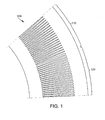
- FIG. 1 a partial perspective view of a filter element 100 is shown according to embodiments of the invention.
- the filter element 100 may include a first set of pleats 110 and a second set of pleats 120.
- the first set of pleats 110 and the second set of pleats 120 are positioned upon a substantially continuous filter media body.
- a substantially continuous body is one in which a plurality of elements are configured to form an assembly which would be recognized as a single unit, e.g., a component with a uniform surface or shape but for a set of clearances/gaps between elements.
- each pleat includes a first tip radius and a first spacing between each pleat.
- each pleat includes a second tip radius and a second spacing between each pleat. It is understood that the first tip radius is substantially different from the second tip radius. For example, as shown in FIG. 1 , the first tip radius is less than the second tip radius. Further, it is understood that the first spacing may be substantially different from the second spacing. For example, as shown in FIG. 1 , the first spacing is larger than the second spacing. Alternatively, it is understood that the first set of pleats 110 and the second set of pleats 120 may include the same notional spacing.
- the tip radius of the pleats in both the first set of pleats 110 and the second set of pleats 120 may be approximately 2 millimeters to approximately 0.5 millimeter.
- the spacing between each pleat in the first set of pleats 110 and the second set of pleats 120 may be approximately 20 millimeters to 1 millimeter.
- the pleat height for each pleat in the first set of pleats 110 and the pleat height for each pleat in the second set of pleats 120 is substantially equal on the filter media body.
- the filter element 100 By sharpening the pleat tips (i.e., a smaller tip radius), and having a larger spacing between the pleats, the allowable space for the airflow through the filter element 100 is increased. This lowers the overall resistance to airflow, and the final pressure drop across the filter. By lowering the final pressure drop across the filter, the filter may have performance benefits in certain environments; such as a higher dust holding capacity (DHC). However, by rounding the pleat tips (i.e., a larger tip radius), and having a smaller spacing between the pleats, a larger mechanical resistance is created, which acts as a benefit in other types of environment conditions. By including a plurality of sets of pleats 110, 120 in the filter element 100, the design of the filter element 100 is optimized for a wider range of operational environments.
- DHC dust holding capacity
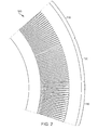
- FIG. 2 a partial perspective view of a filter element 200 according to embodiments of the invention is shown.
- the filter element 200 shown includes the first set of pleats 110 and second set of pleats 120 of filter element 100 shown in FIG. 1 .
- the filter element 200 also includes a third set of pleats 130.
- Each pleat in the third set of pleats 130 similar to each pleat in the first set and second set of pleats 110, 120, include a third tip radius and potentially a third spacing.
- the third tip radius is substantially different from the first tip radius of the first set of pleats 110 and from the second tip radius of the second set of pleats 120.
- the third tip radius may be less than the second tip radius, and the second tip radius may be less than the first tip radius.
- the third spacing of the third set of pleats 130 may be substantially different from the first spacing of the first set of pleats 110 and from the second spacing of the second set of pleats 120.
- second spacing may be larger than the third spacing
- the first spacing may be larger than the second spacing.
- filter element 100, 200 may include any number of sets of pleats.
- filter element 100, 200 shown in FIGS. 1 and 2 are shown to include a first sets of pleats 110 and a second set of pleats 120 (and also a third set of pleats 130 ( FIG. 2 )), where each pleat in the sets of pleats 110, 120, 130 are grouped together, it is understood that filter element 100, 200 may include alternating pleat tips. For example, a pleat of the first set of pleats 110 may be followed by a pleat of the second set of pleats 120, and this pattern may continue for the entire circumference of the filter element 100, 200.
- Filter element 100, 200 may be made from any now known or later developed filter material.
- filter element 100, 200 may be made from cellulose, blends of cellulose and polyester, glass microfiber, blends of glass microfibers and synthetic fibers, and composites. However, it is understood than any filter material may be used.
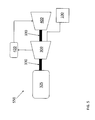
- System 350 may include a gas turbine 300.
- the embodiments of the invention may be applied to any machine that benefits from improved air quality.
- the embodiments of the invention may be similarly applied to different machines such as, but not limited to, gas, steam, or wind turbines, or internal combustion engines.
- System 350 may also include filter element 100 (or filter element 200, as discussed herein) that is operably connected to gas turbine 300.
- Gas turbine 300 may be operably connected to a first load device 325.
- Load device 325 may include, for example, a conventional electric generator, a compressor, a pump, or any other conventional load device.
- Load device 325 and gas turbine 300 may be mechanically coupled by a shaft 330, which may transfer energy between a drive shaft (not shown) of gas turbine 300 and load device 325.
- Combined cycle power plant 450 may include, for example, gas turbine 300 operably connected to first load device 325. Also shown in FIG. 4 is a heat exchanger 420 operably connected to gas turbine 300 and a steam turbine 400.
- System 450 may include filter element 100 (or filter element 200, as discussed herein).
- Heat exchanger 420 may be fluidly connected to both gas turbine 300 and steam turbine 400 via conventional conduits (numbering omitted). Heat exchanger 420 may be a conventional heat recovery steam generator (HRSG), such as those used in conventional combined cycle power systems.
- HRSG heat recovery steam generator
- HRSG may use hot exhaust from gas turbine 300, combined with a water supply, to create steam which is fed to steam turbine 400.
- Steam turbine 400 may optionally be coupled to a second load device 425 (via a second shaft 430).
- Second load device 425 and second shaft 430 may operate substantially similarly to load device 325 and shaft 330 described above.
- a single shaft combined cycle power plant 550 may include a single generator 325 coupled to both gas turbine 300 and steam turbine 400 via a single shaft 330.
Landscapes
- Engineering & Computer Science (AREA)
- Chemical & Material Sciences (AREA)
- Combustion & Propulsion (AREA)
- Mechanical Engineering (AREA)
- General Engineering & Computer Science (AREA)
- Chemical Kinetics & Catalysis (AREA)
- Filtering Of Dispersed Particles In Gases (AREA)
- Filtering Materials (AREA)
- Structures Of Non-Positive Displacement Pumps (AREA)
Applications Claiming Priority (1)
| Application Number | Priority Date | Filing Date | Title |
|---|---|---|---|
| US13/355,631 US9371777B2 (en) | 2012-01-23 | 2012-01-23 | Filter assembly including pleat tip shapes |
Publications (3)
| Publication Number | Publication Date |
|---|---|
| EP2617962A2 true EP2617962A2 (de) | 2013-07-24 |
| EP2617962A3 EP2617962A3 (de) | 2018-03-28 |
| EP2617962B1 EP2617962B1 (de) | 2019-09-25 |
Family
ID=47561465
Family Applications (1)
| Application Number | Title | Priority Date | Filing Date |
|---|---|---|---|
| EP13152027.2A Active EP2617962B1 (de) | 2012-01-23 | 2013-01-21 | Filteranordnung mit Faltspitzenformen |
Country Status (9)
| Country | Link |
|---|---|
| US (2) | US9371777B2 (de) |
| EP (1) | EP2617962B1 (de) |
| JP (1) | JP2013146729A (de) |
| KR (1) | KR20130086182A (de) |
| CN (1) | CN103212256A (de) |
| CA (1) | CA2802246C (de) |
| ES (1) | ES2761871T3 (de) |
| MX (1) | MX344379B (de) |
| PH (1) | PH12013000027A1 (de) |
Families Citing this family (7)
| Publication number | Priority date | Publication date | Assignee | Title |
|---|---|---|---|---|
| US9278301B2 (en) * | 2013-08-16 | 2016-03-08 | 3M Innovative Properties Company | Nestable framed pleated air filter and method of making |
| US9358488B2 (en) | 2013-11-15 | 2016-06-07 | Bha Altair, Llc | Gas turbine filtration system with inlet filter orientation assembly |
| DE102013227208A1 (de) * | 2013-12-30 | 2015-07-02 | Siemens Aktiengesellschaft | Dichtsystem für eine Dampfturbine sowie Dampfturbine |
| CN109890666B (zh) | 2016-10-20 | 2022-03-11 | 康明斯滤清系统知识产权公司 | 平坦的片的间断的定向凸起 |
| US11376541B2 (en) | 2016-12-15 | 2022-07-05 | Cummins Filtration Ip, Inc. | Tetrahedral filter media |
| CN110475600B (zh) | 2017-04-11 | 2021-10-22 | 康明斯过滤Ip公司 | 板式过滤器元件 |
| WO2021118524A1 (en) | 2019-12-09 | 2021-06-17 | Cummins Filtration Inc. | Formed filter media |
Family Cites Families (15)
| Publication number | Priority date | Publication date | Assignee | Title |
|---|---|---|---|---|
| US5320657A (en) | 1993-04-30 | 1994-06-14 | Dana Corporation | Staggered short pleat air filter |
| US5897776A (en) | 1997-10-03 | 1999-04-27 | Dana Corporation | Filter media configuration |
| DE69930743T2 (de) | 1998-06-29 | 2007-04-19 | Pall Corp. | Faltenfilter und verfahren zur seiner herstellung |
| US20030024872A1 (en) | 1999-06-30 | 2003-02-06 | Pti Advanced Filtration, Inc. | Filter having staged pleating |
| DE60336060D1 (de) | 2002-07-10 | 2011-03-31 | Donaldson Co Inc | Gefaltetes filtermaterial und verfahren zu dessen herstellung |
| US7648546B2 (en) * | 2006-01-06 | 2010-01-19 | Cummins Filtration Ip Inc. | Filter with variable pleat depth |
| US7931723B2 (en) | 2006-03-09 | 2011-04-26 | Donaldson Company, Inc. | Filter assembly with pleated media pockets, and methods |
| US8585788B2 (en) * | 2006-03-31 | 2013-11-19 | Coaltek, Inc. | Methods and systems for processing solid fuel |
| JP2007331739A (ja) * | 2006-05-17 | 2007-12-27 | Denso Corp | 車両用空調装置 |
| US20090020472A1 (en) * | 2007-07-19 | 2009-01-22 | 3M Innovative Properties Company | Pleated filter |
| EP2070577A1 (de) * | 2007-12-10 | 2009-06-17 | Carl Freudenberg KG | Komprimierbares Filterelement mit umklappbarer Dichtlippe |
| JP2009297666A (ja) | 2008-06-16 | 2009-12-24 | Frontier Sangyo Kk | プリーツ状エアフィルター及びその製法 |
| WO2010146462A2 (en) | 2009-06-19 | 2010-12-23 | Entegris, Inc. | Filter pleat structure |
| JP5711230B2 (ja) | 2009-08-03 | 2015-04-30 | ドナルドソン カンパニー,インコーポレイティド | テーパ付き縦溝流路を有する縦溝流路付き濾過媒体を形成する方法および装置 |
| CA2787822A1 (en) * | 2010-01-25 | 2011-07-28 | Donaldson Company, Inc. | Pleated filtration media having tapered flutes |
-
2012
- 2012-01-23 US US13/355,631 patent/US9371777B2/en active Active
-
2013
- 2013-01-17 JP JP2013005865A patent/JP2013146729A/ja active Pending
- 2013-01-17 CA CA2802246A patent/CA2802246C/en active Active
- 2013-01-21 ES ES13152027T patent/ES2761871T3/es active Active
- 2013-01-21 EP EP13152027.2A patent/EP2617962B1/de active Active
- 2013-01-22 PH PH12013000027A patent/PH12013000027A1/en unknown
- 2013-01-22 KR KR1020130007044A patent/KR20130086182A/ko not_active Withdrawn
- 2013-01-23 CN CN2013100239713A patent/CN103212256A/zh active Pending
- 2013-01-23 MX MX2013000964A patent/MX344379B/es active IP Right Grant
-
2016
- 2016-05-18 US US15/158,392 patent/US10215093B2/en active Active
Non-Patent Citations (1)
| Title |
|---|
| None |
Also Published As
| Publication number | Publication date |
|---|---|
| PH12013000027A1 (en) | 2014-08-11 |
| US10215093B2 (en) | 2019-02-26 |
| CA2802246A1 (en) | 2013-07-23 |
| US9371777B2 (en) | 2016-06-21 |
| MX344379B (es) | 2016-12-09 |
| ES2761871T3 (es) | 2020-05-21 |
| EP2617962B1 (de) | 2019-09-25 |
| US20160265436A1 (en) | 2016-09-15 |
| JP2013146729A (ja) | 2013-08-01 |
| US20170234221A9 (en) | 2017-08-17 |
| KR20130086182A (ko) | 2013-07-31 |
| EP2617962A3 (de) | 2018-03-28 |
| MX2013000964A (es) | 2013-07-22 |
| CN103212256A (zh) | 2013-07-24 |
| CA2802246C (en) | 2019-07-16 |
| US20130189081A1 (en) | 2013-07-25 |
Similar Documents
| Publication | Publication Date | Title |
|---|---|---|
| US10215093B2 (en) | Filter assembly including pleat tip shapes | |
| US10323572B2 (en) | Gas turbine filtration system with inlet filter orientation assembly | |
| US9115585B2 (en) | Seal assembly for gas turbine | |
| US9810070B2 (en) | Turbine rotor blade for a turbine section of a gas turbine | |
| US9709275B2 (en) | Debris removal system | |
| CN102188856A (zh) | 深层过滤型空气过滤介质及深层过滤型空气滤筒 | |
| CN107869734B (zh) | 具有减少的拐角泄漏的先进密封件 | |
| EP3299680B1 (de) | Dichtungsanordnung und zugehörige gasturbine | |
| EP3249164B1 (de) | Seitendichtung mit reduzierter eckleckage | |
| US20160084161A1 (en) | Inlet air filtration system with self-cleaning hydrophobic filter bag | |
| US9200568B1 (en) | Inlet air filtration system with self-cleaning filter bag | |
| WO2015084979A1 (en) | Filter media and method of forming thereof | |
| US20180313230A1 (en) | Segemented Liner | |
| CN103566657A (zh) | 过滤器介质和包括其的过滤器装置 | |
| US9309776B2 (en) | Replaceable seals for turbine engine components and methods for installing the same | |
| US20140041393A1 (en) | Systems and methods for processing inlet air | |
| JP2024544376A (ja) | ターボ機械翼形部用ワイヤスクリーン粒子フィルタ | |
| CN216498205U (zh) | 耐高温滤芯 | |
| Sutherland | Air filtration in industry: Gas turbine intake air filtration | |
| CN206801709U (zh) | 用于燃气轮机进气口的过滤装置 | |
| Freedom Composite | Donaldson and BBA scoop AFS 2005 awards |
Legal Events
| Date | Code | Title | Description |
|---|---|---|---|
| PUAI | Public reference made under article 153(3) epc to a published international application that has entered the european phase |
Free format text: ORIGINAL CODE: 0009012 |
|
| AK | Designated contracting states |
Kind code of ref document: A2 Designated state(s): AL AT BE BG CH CY CZ DE DK EE ES FI FR GB GR HR HU IE IS IT LI LT LU LV MC MK MT NL NO PL PT RO RS SE SI SK SM TR |
|
| AX | Request for extension of the european patent |
Extension state: BA ME |
|
| RAP1 | Party data changed (applicant data changed or rights of an application transferred) |
Owner name: BHA ALTAIR, LLC |
|
| PUAL | Search report despatched |
Free format text: ORIGINAL CODE: 0009013 |
|
| AK | Designated contracting states |
Kind code of ref document: A3 Designated state(s): AL AT BE BG CH CY CZ DE DK EE ES FI FR GB GR HR HU IE IS IT LI LT LU LV MC MK MT NL NO PL PT RO RS SE SI SK SM TR |
|
| AX | Request for extension of the european patent |
Extension state: BA ME |
|
| RIC1 | Information provided on ipc code assigned before grant |
Ipc: F02C 7/052 20060101AFI20180221BHEP Ipc: B01D 46/52 20060101ALI20180221BHEP Ipc: F02C 7/055 20060101ALI20180221BHEP |
|
| STAA | Information on the status of an ep patent application or granted ep patent |
Free format text: STATUS: REQUEST FOR EXAMINATION WAS MADE |
|
| 17P | Request for examination filed |
Effective date: 20180918 |
|
| RBV | Designated contracting states (corrected) |
Designated state(s): AL AT BE BG CH CY CZ DE DK EE ES FI FR GB GR HR HU IE IS IT LI LT LU LV MC MK MT NL NO PL PT RO RS SE SI SK SM TR |
|
| GRAP | Despatch of communication of intention to grant a patent |
Free format text: ORIGINAL CODE: EPIDOSNIGR1 |
|
| STAA | Information on the status of an ep patent application or granted ep patent |
Free format text: STATUS: GRANT OF PATENT IS INTENDED |
|
| INTG | Intention to grant announced |
Effective date: 20190411 |
|
| GRAS | Grant fee paid |
Free format text: ORIGINAL CODE: EPIDOSNIGR3 |
|
| GRAA | (expected) grant |
Free format text: ORIGINAL CODE: 0009210 |
|
| STAA | Information on the status of an ep patent application or granted ep patent |
Free format text: STATUS: THE PATENT HAS BEEN GRANTED |
|
| AK | Designated contracting states |
Kind code of ref document: B1 Designated state(s): AL AT BE BG CH CY CZ DE DK EE ES FI FR GB GR HR HU IE IS IT LI LT LU LV MC MK MT NL NO PL PT RO RS SE SI SK SM TR |
|
| REG | Reference to a national code |
Ref country code: GB Ref legal event code: FG4D |
|
| REG | Reference to a national code |
Ref country code: CH Ref legal event code: EP |
|
| REG | Reference to a national code |
Ref country code: DE Ref legal event code: R096 Ref document number: 602013060863 Country of ref document: DE |
|
| REG | Reference to a national code |
Ref country code: AT Ref legal event code: REF Ref document number: 1184048 Country of ref document: AT Kind code of ref document: T Effective date: 20191015 |
|
| REG | Reference to a national code |
Ref country code: IE Ref legal event code: FG4D |
|
| REG | Reference to a national code |
Ref country code: NL Ref legal event code: MP Effective date: 20190925 |
|
| PG25 | Lapsed in a contracting state [announced via postgrant information from national office to epo] |
Ref country code: FI Free format text: LAPSE BECAUSE OF FAILURE TO SUBMIT A TRANSLATION OF THE DESCRIPTION OR TO PAY THE FEE WITHIN THE PRESCRIBED TIME-LIMIT Effective date: 20190925 Ref country code: HR Free format text: LAPSE BECAUSE OF FAILURE TO SUBMIT A TRANSLATION OF THE DESCRIPTION OR TO PAY THE FEE WITHIN THE PRESCRIBED TIME-LIMIT Effective date: 20190925 Ref country code: NO Free format text: LAPSE BECAUSE OF FAILURE TO SUBMIT A TRANSLATION OF THE DESCRIPTION OR TO PAY THE FEE WITHIN THE PRESCRIBED TIME-LIMIT Effective date: 20191225 Ref country code: BG Free format text: LAPSE BECAUSE OF FAILURE TO SUBMIT A TRANSLATION OF THE DESCRIPTION OR TO PAY THE FEE WITHIN THE PRESCRIBED TIME-LIMIT Effective date: 20191225 Ref country code: SE Free format text: LAPSE BECAUSE OF FAILURE TO SUBMIT A TRANSLATION OF THE DESCRIPTION OR TO PAY THE FEE WITHIN THE PRESCRIBED TIME-LIMIT Effective date: 20190925 Ref country code: LT Free format text: LAPSE BECAUSE OF FAILURE TO SUBMIT A TRANSLATION OF THE DESCRIPTION OR TO PAY THE FEE WITHIN THE PRESCRIBED TIME-LIMIT Effective date: 20190925 |
|
| REG | Reference to a national code |
Ref country code: LT Ref legal event code: MG4D |
|
| PG25 | Lapsed in a contracting state [announced via postgrant information from national office to epo] |
Ref country code: RS Free format text: LAPSE BECAUSE OF FAILURE TO SUBMIT A TRANSLATION OF THE DESCRIPTION OR TO PAY THE FEE WITHIN THE PRESCRIBED TIME-LIMIT Effective date: 20190925 Ref country code: GR Free format text: LAPSE BECAUSE OF FAILURE TO SUBMIT A TRANSLATION OF THE DESCRIPTION OR TO PAY THE FEE WITHIN THE PRESCRIBED TIME-LIMIT Effective date: 20191226 Ref country code: LV Free format text: LAPSE BECAUSE OF FAILURE TO SUBMIT A TRANSLATION OF THE DESCRIPTION OR TO PAY THE FEE WITHIN THE PRESCRIBED TIME-LIMIT Effective date: 20190925 |
|
| REG | Reference to a national code |
Ref country code: AT Ref legal event code: MK05 Ref document number: 1184048 Country of ref document: AT Kind code of ref document: T Effective date: 20190925 |
|
| PG25 | Lapsed in a contracting state [announced via postgrant information from national office to epo] |
Ref country code: PL Free format text: LAPSE BECAUSE OF FAILURE TO SUBMIT A TRANSLATION OF THE DESCRIPTION OR TO PAY THE FEE WITHIN THE PRESCRIBED TIME-LIMIT Effective date: 20190925 Ref country code: PT Free format text: LAPSE BECAUSE OF FAILURE TO SUBMIT A TRANSLATION OF THE DESCRIPTION OR TO PAY THE FEE WITHIN THE PRESCRIBED TIME-LIMIT Effective date: 20200127 Ref country code: AL Free format text: LAPSE BECAUSE OF FAILURE TO SUBMIT A TRANSLATION OF THE DESCRIPTION OR TO PAY THE FEE WITHIN THE PRESCRIBED TIME-LIMIT Effective date: 20190925 Ref country code: NL Free format text: LAPSE BECAUSE OF FAILURE TO SUBMIT A TRANSLATION OF THE DESCRIPTION OR TO PAY THE FEE WITHIN THE PRESCRIBED TIME-LIMIT Effective date: 20190925 Ref country code: EE Free format text: LAPSE BECAUSE OF FAILURE TO SUBMIT A TRANSLATION OF THE DESCRIPTION OR TO PAY THE FEE WITHIN THE PRESCRIBED TIME-LIMIT Effective date: 20190925 Ref country code: AT Free format text: LAPSE BECAUSE OF FAILURE TO SUBMIT A TRANSLATION OF THE DESCRIPTION OR TO PAY THE FEE WITHIN THE PRESCRIBED TIME-LIMIT Effective date: 20190925 Ref country code: RO Free format text: LAPSE BECAUSE OF FAILURE TO SUBMIT A TRANSLATION OF THE DESCRIPTION OR TO PAY THE FEE WITHIN THE PRESCRIBED TIME-LIMIT Effective date: 20190925 |
|
| REG | Reference to a national code |
Ref country code: ES Ref legal event code: FG2A Ref document number: 2761871 Country of ref document: ES Kind code of ref document: T3 Effective date: 20200521 |
|
| PG25 | Lapsed in a contracting state [announced via postgrant information from national office to epo] |
Ref country code: SM Free format text: LAPSE BECAUSE OF FAILURE TO SUBMIT A TRANSLATION OF THE DESCRIPTION OR TO PAY THE FEE WITHIN THE PRESCRIBED TIME-LIMIT Effective date: 20190925 Ref country code: IS Free format text: LAPSE BECAUSE OF FAILURE TO SUBMIT A TRANSLATION OF THE DESCRIPTION OR TO PAY THE FEE WITHIN THE PRESCRIBED TIME-LIMIT Effective date: 20200224 Ref country code: SK Free format text: LAPSE BECAUSE OF FAILURE TO SUBMIT A TRANSLATION OF THE DESCRIPTION OR TO PAY THE FEE WITHIN THE PRESCRIBED TIME-LIMIT Effective date: 20190925 Ref country code: CZ Free format text: LAPSE BECAUSE OF FAILURE TO SUBMIT A TRANSLATION OF THE DESCRIPTION OR TO PAY THE FEE WITHIN THE PRESCRIBED TIME-LIMIT Effective date: 20190925 |
|
| REG | Reference to a national code |
Ref country code: DE Ref legal event code: R097 Ref document number: 602013060863 Country of ref document: DE |
|
| PG2D | Information on lapse in contracting state deleted |
Ref country code: IS |
|
| PG25 | Lapsed in a contracting state [announced via postgrant information from national office to epo] |
Ref country code: IS Free format text: LAPSE BECAUSE OF FAILURE TO SUBMIT A TRANSLATION OF THE DESCRIPTION OR TO PAY THE FEE WITHIN THE PRESCRIBED TIME-LIMIT Effective date: 20200126 Ref country code: DK Free format text: LAPSE BECAUSE OF FAILURE TO SUBMIT A TRANSLATION OF THE DESCRIPTION OR TO PAY THE FEE WITHIN THE PRESCRIBED TIME-LIMIT Effective date: 20190925 |
|
| PLBE | No opposition filed within time limit |
Free format text: ORIGINAL CODE: 0009261 |
|
| STAA | Information on the status of an ep patent application or granted ep patent |
Free format text: STATUS: NO OPPOSITION FILED WITHIN TIME LIMIT |
|
| PG25 | Lapsed in a contracting state [announced via postgrant information from national office to epo] |
Ref country code: MC Free format text: LAPSE BECAUSE OF FAILURE TO SUBMIT A TRANSLATION OF THE DESCRIPTION OR TO PAY THE FEE WITHIN THE PRESCRIBED TIME-LIMIT Effective date: 20190925 |
|
| REG | Reference to a national code |
Ref country code: CH Ref legal event code: PL |
|
| 26N | No opposition filed |
Effective date: 20200626 |
|
| REG | Reference to a national code |
Ref country code: BE Ref legal event code: MM Effective date: 20200131 |
|
| PG25 | Lapsed in a contracting state [announced via postgrant information from national office to epo] |
Ref country code: LU Free format text: LAPSE BECAUSE OF NON-PAYMENT OF DUE FEES Effective date: 20200121 |
|
| PG25 | Lapsed in a contracting state [announced via postgrant information from national office to epo] |
Ref country code: LI Free format text: LAPSE BECAUSE OF NON-PAYMENT OF DUE FEES Effective date: 20200131 Ref country code: SI Free format text: LAPSE BECAUSE OF FAILURE TO SUBMIT A TRANSLATION OF THE DESCRIPTION OR TO PAY THE FEE WITHIN THE PRESCRIBED TIME-LIMIT Effective date: 20190925 Ref country code: BE Free format text: LAPSE BECAUSE OF NON-PAYMENT OF DUE FEES Effective date: 20200131 Ref country code: CH Free format text: LAPSE BECAUSE OF NON-PAYMENT OF DUE FEES Effective date: 20200131 |
|
| PG25 | Lapsed in a contracting state [announced via postgrant information from national office to epo] |
Ref country code: IE Free format text: LAPSE BECAUSE OF NON-PAYMENT OF DUE FEES Effective date: 20200121 |
|
| REG | Reference to a national code |
Ref country code: GB Ref legal event code: 732E Free format text: REGISTERED BETWEEN 20210826 AND 20210901 |
|
| REG | Reference to a national code |
Ref country code: DE Ref legal event code: R081 Ref document number: 602013060863 Country of ref document: DE Owner name: PARKER-HANNIFIN CORP., CLEVELAND, US Free format text: FORMER OWNER: BHA ALTAIR, LLC, FRANKLIN, TENN., US |
|
| REG | Reference to a national code |
Ref country code: ES Ref legal event code: PC2A Owner name: PARKER-HANNIFIN CORPORATION Effective date: 20220113 |
|
| PG25 | Lapsed in a contracting state [announced via postgrant information from national office to epo] |
Ref country code: TR Free format text: LAPSE BECAUSE OF FAILURE TO SUBMIT A TRANSLATION OF THE DESCRIPTION OR TO PAY THE FEE WITHIN THE PRESCRIBED TIME-LIMIT Effective date: 20190925 Ref country code: MT Free format text: LAPSE BECAUSE OF FAILURE TO SUBMIT A TRANSLATION OF THE DESCRIPTION OR TO PAY THE FEE WITHIN THE PRESCRIBED TIME-LIMIT Effective date: 20190925 Ref country code: CY Free format text: LAPSE BECAUSE OF FAILURE TO SUBMIT A TRANSLATION OF THE DESCRIPTION OR TO PAY THE FEE WITHIN THE PRESCRIBED TIME-LIMIT Effective date: 20190925 |
|
| PG25 | Lapsed in a contracting state [announced via postgrant information from national office to epo] |
Ref country code: MK Free format text: LAPSE BECAUSE OF FAILURE TO SUBMIT A TRANSLATION OF THE DESCRIPTION OR TO PAY THE FEE WITHIN THE PRESCRIBED TIME-LIMIT Effective date: 20190925 |
|
| P01 | Opt-out of the competence of the unified patent court (upc) registered |
Effective date: 20230524 |
|
| PGFP | Annual fee paid to national office [announced via postgrant information from national office to epo] |
Ref country code: GB Payment date: 20260127 Year of fee payment: 14 |
|
| PGFP | Annual fee paid to national office [announced via postgrant information from national office to epo] |
Ref country code: ES Payment date: 20260202 Year of fee payment: 14 |
|
| PGFP | Annual fee paid to national office [announced via postgrant information from national office to epo] |
Ref country code: DE Payment date: 20260128 Year of fee payment: 14 |
|
| PGFP | Annual fee paid to national office [announced via postgrant information from national office to epo] |
Ref country code: IT Payment date: 20260121 Year of fee payment: 14 |
|
| PGFP | Annual fee paid to national office [announced via postgrant information from national office to epo] |
Ref country code: FR Payment date: 20260126 Year of fee payment: 14 |