EP2618005B1 - Assemblage de composant avec élément de rivet et plaque de pression - Google Patents
Assemblage de composant avec élément de rivet et plaque de pression Download PDFInfo
- Publication number
- EP2618005B1 EP2618005B1 EP13151961.3A EP13151961A EP2618005B1 EP 2618005 B1 EP2618005 B1 EP 2618005B1 EP 13151961 A EP13151961 A EP 13151961A EP 2618005 B1 EP2618005 B1 EP 2618005B1
- Authority
- EP
- European Patent Office
- Prior art keywords
- section
- component
- pressure plate
- functional
- connection
- Prior art date
- Legal status (The legal status is an assumption and is not a legal conclusion. Google has not performed a legal analysis and makes no representation as to the accuracy of the status listed.)
- Active
Links
Images




Classifications
-
- F—MECHANICAL ENGINEERING; LIGHTING; HEATING; WEAPONS; BLASTING
- F16—ENGINEERING ELEMENTS AND UNITS; GENERAL MEASURES FOR PRODUCING AND MAINTAINING EFFECTIVE FUNCTIONING OF MACHINES OR INSTALLATIONS; THERMAL INSULATION IN GENERAL
- F16B—DEVICES FOR FASTENING OR SECURING CONSTRUCTIONAL ELEMENTS OR MACHINE PARTS TOGETHER, e.g. NAILS, BOLTS, CIRCLIPS, CLAMPS, CLIPS OR WEDGES; JOINTS OR JOINTING
- F16B19/00—Bolts without screw-thread; Pins, including deformable elements; Rivets
- F16B19/04—Rivets; Spigots or the like fastened by riveting
- F16B19/08—Hollow rivets; Multi-part rivets
-
- F—MECHANICAL ENGINEERING; LIGHTING; HEATING; WEAPONS; BLASTING
- F16—ENGINEERING ELEMENTS AND UNITS; GENERAL MEASURES FOR PRODUCING AND MAINTAINING EFFECTIVE FUNCTIONING OF MACHINES OR INSTALLATIONS; THERMAL INSULATION IN GENERAL
- F16B—DEVICES FOR FASTENING OR SECURING CONSTRUCTIONAL ELEMENTS OR MACHINE PARTS TOGETHER, e.g. NAILS, BOLTS, CIRCLIPS, CLAMPS, CLIPS OR WEDGES; JOINTS OR JOINTING
- F16B37/00—Nuts or like thread-engaging members
- F16B37/04—Devices for fastening nuts to surfaces, e.g. sheets, plates
- F16B37/06—Devices for fastening nuts to surfaces, e.g. sheets, plates by means of welding or riveting
- F16B37/062—Devices for fastening nuts to surfaces, e.g. sheets, plates by means of welding or riveting by means of riveting
- F16B37/065—Devices for fastening nuts to surfaces, e.g. sheets, plates by means of welding or riveting by means of riveting by deforming the material of the nut
Definitions
- the invention relates to a component assembly composed of at least a combination of a functional rivet element having a flange section and a connection section and a pressure plate, in particular a pressure plate having an opening, and a component which is a panel of composite material or sheet metal.
- Document GB 678,532 relates to a stud supporting arrangement suitable for the securing of studs to the sole of boots and shoes.
- Document US 2008/0079241 A1 relates to an airbag cover with an ornamental body fixed to said cover by a back plate.
- EP 0 179 367 A2 relates to an eyelet assembly including an eyelet body and a seat plate formed by plastic material which are adapted to be assembled together on a piece of a fabric or the like.
- Fiber reinforcement can for example take the form of tapes, fabrics, felts and mats.
- coachwork parts of polyester resins reinforced with glass fibers and plastics, such as epoxy resins, reinforced with carbon fibers are frequently used in motor car construction.
- Numerous further components, such as consoles and cladding, are likewise also manufactured from such composite materials in practice.
- carbon fibers as a reinforcement fabrics of carbon fibers are frequently used because one can then obtain a reinforcement in all directions of the component.
- Composite materials are composed of an arbitrary reinforcement material or fibers and an arbitrary, plastically deformable or meltable matrix material.
- composite material is used here in accordance with the invention and for this reason not only comprises plastics with fiber reinforcement, but, for example, also comprises matrix materials of metal, e.g. aluminum with a reinforcement material, such as e.g. carbon fiber or ceramic particles.
- the present invention primarily uses those composite materials which use a thermoplastic material, i.e. a thermoplastic as matrix material.
- a thermoplastic material i.e. a thermoplastic as matrix material.
- Such materials or composite materials are characterized in that they are soft or become pasty at elevated temperatures lying below the melting point.
- duroplastics can also be used as a matrix material provided these are adequately soft or become soft or pasty at elevated temperature, and indeed at temperatures which lie beneath the temperatures at which the relevant matrix material is permanently damaged.
- the invention can also be used in combination with composite materials which include matrix materials which are indeed not thermoplastics but which have not yet reached their final state, but are rather present in a state in which they are soft or pasty with or without heating but which can be transferred into a harder state in the course of time or because of external influences, for example, by the action of ultraviolet light or humidity or otherwise through a progressive polymerization or cross-linking.
- Both rivet elements and also bolt or nut elements can be considered as fastener elements or connector elements which can all be subsumated under the term "functional elements".
- the term “functional element” applies also for clips and bearings in the framework of the present invention which can likewise be secured to composite materials.
- the component can be heated for the attachment of functional elements, at least in a region of a hole provided for the attachment, to a temperature dependent on the respective material at which the material of the composite material does not melt, but is softened or pasted to a desired degree. If the material is, for example PA6, then the heating can take place to a temperature of for example 260 °C.
- the above explanations are not to be understood as statements exemplifying the background of the invention, but rather also form a part of the disclosure associated with the invention. On the attachment of functional elements to components composed of composite material or a different material it is striven for to not focus the loading onto a small area of the region of the component surrounding the hole.
- the object underlying the invention is to provide a possibility for the attachment of functional elements to components manufactured of composite material or of relatively soft sheet metal which meets the above-named requirements as well as possible.
- a component assembly comprising at least a combination of a functional rivet element having a flange section and a connection section and a pressure plate and a component having the further features of claim 1.
- a component assembly with a combination of a functional, rivet element having a flange section and a connection section, a pressure plate, in particular a pressure plate having an opening, and a component, which is a panel of composite material or sheet metal, wherein the functional rivet element and the pressure plate are arranged on opposite sides of a hole of the component and are connected together via the connection section which extends through the hole by riveting in order to clamp a region of the component surrounding the hole between the flange section and the pressure plate and wherein the pressure side of the pressure plate confronting the component in the attached state is provided with a means providing security against rotation.
- the pressure side of a combination has a contour which differs from a circular shape.
- a contour of the pressure side can have a circular basic shape from which at least one missing section is removed and/or to which an added section is added.
- the missing section is a circular sector or a circular segment, or the missing section is provided in the form of a cutout or of a bay.
- a plurality of missing sections and/or added sections distributed in the peripheral direction are provided.
- the pressure side can be bounded with a sharp edge at least regionally.
- the pressure side can be flat or the pressure side can be provided with one or more raised portions.
- Such a raised portion can have an elongated, in particular rib-like or web-like shape and/or the raised portion can follow a part of the contour of the pressure side.
- the raised portion is made non-cutting at its free end.
- the side of the pressure plate remote from the component in the attached state is provided with a collar surrounding the opening, with the collar in particular being designed in order to cooperate with a rivet section forming the connection section.
- connection section is formed at least regionally at a rivet section.
- the functional rivet element and/or the pressure plate is provided with means providing security against rotation which, in the attached state, are active between the functional rivet element and the pressure plate, with the means providing security against rotation in particular being formed at the connection section.
- the means providing security against rotation are provided in a form of ribs extending in the axial direction and arranged distributed in the peripheral direction, with the ribs preferably extending at least approximately from a transition surface between the flange section and the connection section to a transition surface at the free end of the connection section.
- a transition surface provided between the flange section and the connection section of the functional rivet element has a curved extent, in particular a concavely curved extent.
- the flange section preferably has a transition between an end section and a section with a reduced diameter relative to the end section, with the transition being formed by a transition surface which have an inclined or in particular concavely curved extent.
- the flange section could have a transition between an end section and a section with a reduced diameter in comparison with the end section, the transition being made of step-like shape, with the transition in particular having a radially extending transition surface.
- an internal diameter of an opening of the pressure plate corresponds at least approximately to the outer diameter of the connection section of the functional rivet element.
- an outer diameter of the pressure plate is larger than the largest diameter of the flange section of the functional rivet element.
- the invention is based on the concept of not attaching the functional rivet element alone to a component but rather to additionally use a pressure plate whereby functional rivet elements and pressure plate being attached to the component coming from opposite sides of the component.
- the attached state is characterized in that, on the one hand, the connection section of the functional rivet element and the pressure plate are connected to one another and indeed at the side of the component at which the pressure plate is located.
- the pressure plate is provided with means providing security against rotation which cooperates with the component.
- a pressure plate provided in addition to the functional rivet element further enables a particularly secure firm and stable clamping of the region of the component surrounding the hole between the flange section of the functional rivet element and the pressure plate and thus a secure retention of the functional rivet element or of the combination of functional rivet element and pressure plate at the component.
- the pressure plate contributes to the security against rotation or can serve at least largely alone from the security against rotation. For this purpose the pressure side of the pressure plate dimensioned to be comparatively large is exploited.
- connection section of the functional rivet elements and of the pressure plate can in particular be a form-fitted connection which is effected essentially in the axial direction
- connection between the connection section of the functional rivet element and the pressure plate can include a security against rotation of the connection section relative to the pressure plate.
- the functional rivet element and/or the pressure plate can be provided with means providing security against rotation which, in the attached state, are effective between the functional rivet element and the pressure plate.
- the functional rivet element is connected in a manner secure against rotation with the pressure plate, whereas the pressure plate is further connected in a manner secure against rotation with the component. The securing of the functional rivet element to the component in a manner securing against rotation thus results directly via the pressure plate.
- the security against rotation between the pressure plate and the component can take place partly or exclusively in that the pressure side of the pressure plate confronting the component is provided with means providing security against rotation in particular in the form of, for example, discretely distributed raised portions or projections which, on attachment to the components, can be pressed into the one side of the component.
- the raised portions can be elongated or point-like raised portions.
- the recesses can also be provided at the pressure plate into which material of the component enters during the attachment.
- the pressure side has a contour which deviates from a circular shape.
- This design enables a particular or particularly simple way of manufacturing a security against rotation between the pressure plate and the component which consists therein that the circumstance is exploited that, on the attachment of the pressure plate at the component, the pressure plate is at least slightly pressed into the component. Due to the pressure side having a contour which deviates from the circular shape a security against rotation automatically results through this.
- components of composite materials or relatively soft sheet metals have the alleged disadvantage that they are relatively "yielding" and can be pressed in with relatively small forces. On the one hand, one endeavors to avoid such a "coining" as far as possible. On the other hand, practice has shown that a small degree of such pressing in can be tolerated without problem.
- the pressing in or "coining" which is unavoidable in practice is exploited in order to produce a security against rotation to the pressure plate and the component.
- the pressure side of the pressure plate is provided with a contour which differs from a circular shape. It can provided that the pressure plate is bounded at least regionally by a sharp edge, i.e. the contour of the pressure plate is formed at least regionally by a sharp edge.
- the side of the pressure plate remote from the component in the attached state is provided with a collar surrounding the opening. This collar serves in particular to cooperate with a rivet section formed by the connection section of the functional rivet element. In this way the pressure plate is acted on by the rivet section of the functional rivet element via the collar, whereby an advantageous introduction of the load is achieved into the section of the pressure plate contacting the component.
- the functional element has a flange section and a connection section and is formed to be arranged on a side of the component and whose connection section is adapted to pass through the component, either by passing through a premanufactured hole or by piercing the component and simultaneously passing through the component.
- the pressure plate is pressed into the component for the realization of the connection providing security against rotation.
- the rivet connection in particular exists between a rivet section which includes the free end of the connection section and the side of the pressure plate remote from the component, preferably between the connection section and a collar which is arranged at a side of the pressure plate remote from the component and which surrounds an opening.
- a form-fitted connection providing security against rotation exists between the functional rivet element and the pressure plate.
- the flange section is pressed into the component, in particular in such a way that the flange section terminates with the component or is recessed in the component or in that the flange section projects beyond the component.
- the hole of the component has an axial extent with a constant internal diameter which is preferably smaller than the outer diameter of an end section of the step-like flange section or in that the hole of the component has a stepped axial extent, with an end section of the flange section being received in a section of the hole having the largest internal diameter.
- a method for the attachment of functional rivet elements to components being panels of composite materials or sheet metal in which method the functional rivet element and a pressure plate in particular provided with an opening are arranged on opposite sides of a hole of the component, in particular a previously manufactured hole, the functional rivet element and the pressure plate are connected to one another via a connection section of the functional rivet element extending through the hole, a region of the component surrounding the hole is trapped between a flange section of the functional rivet element and the pressure plate and means providing security against rotation are provided at the pressure side of the pressure plate adjacent to the component are brought into form-fitted engagement with the component.
- the pressure plate is pressed into the component for the realization of the connection providing security against rotation.
- the rivet connection is in particular produced between a rivet section including the free end of the connection section and the side of the pressure plate remote from the component, preferably between the connection section and a collar which surrounds an opening and which is arranged at the side of the pressure plate remote from the component.
- a form-fitted connection providing security against rotation is produced between the functional element and the pressure plate.
- the flange section is pressed into the component, in particular in such a way that the flange section terminates flush with the component or is recessed into the component, or in that the flange projects beyond the component.
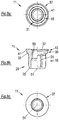
- the Figs. 1 and 2 show different views of the functional rivet element 11 of the component assembly in accordance with the invention in accordance with the first embodiment.
- the functional rivet element 11 is formed as a rivet nut which has a passage defining a central axis 51 (see Fig. 2b ) and with an internal thread 59 (see Fig. 2b ) extending over a part of the axial length.
- the functional rivet element 11 includes a flange section 13 and a cylindrical connection section 15.
- the connection section 15 is formed at least partly in a thread-free region surrounding the free end of the connection section 15 as a rivet section 29 (see Fig. 2b ).
- the internal thread 59 extends from an end of the functional rivet element 11 including the flange section into the connection section 15 and up to the free end of the connection section 15 designed as the rivet section 29.
- connection section 15 is provided at its outer side with ribs 31 which extend in the axial direction and are arranged distributed in the circumferential direction and which serve as means providing security against rotation and can cooperate, in the installed state, with a pressure plate 17 (see Figs. 3 to 5 ).
- the ribs 31 extend between a convexly curved transition surface 35 at the free end of the connection section 15 and a concavely curved transition surface 33 between the connection section 15 and the flange section 13.
- the top view of the functional rivet element 11 of Fig. 2a shows six such ribs 31 it should, however, be noted that recesses (not shown) can likewise be provided rather than ribs. Moreover, the number of ribs (recesses) can be arbitrarily selected, e.g. 1 to 12 such ribs 31 can provided depending on the size of the functional rivet element 11 and/or the intended application of the functional rivet element 11.
- the flange section 13 includes a cylindrical end section 37 at which a section 39 adjoins with reduced diameter. The section 39 with reduced diameter merges via the curved transition surface 33 into the connection section 15 having a further reduced outer diameter. It should be noted in this connection that the cylindrical end section 37 includes a substantially planar end face in the variant shown in Figs.
- a step is present between the end section 37 and the adjoining section 39 with reduced diameter, the step including a radially extending transition surface 43 (see e.g. Fig. 1b ).
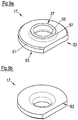
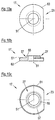
- the Figs. 3 and 4 show an embodiment of a pressure plate 17 of the component assembly in accordance with the invention.
- the pressure plate 17 has a disk section with the disk section having a circular basic shape differing from a circular shape and the cross-section of which is substantially constant over the axial height. It should be noted that the pressure plate 17 described herein can also be termed a washer.
- the deviation from the circular shape results in the fact that missing sections 23 are taken away from the circular shape.
- a missing section 23 is provided in the form of a circular segment.
- further missing sections 23 in the form of bays are provided which are distributed in the peripheral direction.
- the disk section is provided with a sharp edge 63.
- the disk section can be designed with a surrounding sharp edge, with it alternatively also being possible to provide the sharp edge transition between the pressure side and the outer side of the disk section of the pressure plate 17 only regionally. It is also possible to dispense fully with the sharp edged design since in the illustrated embodiment the pressure side is provided with elongated ribs or web-like raised portions 25 which follow the contour of a pressure plate in the region of the mentioned bays 23. As the detail in accordance with Fig. 3c shows, the end faces 53 of the raised portions 23 are made flat, i.e. the elongated raised portions 25 are not cutting edges. In this way a situation is achieved in which, in the attached state, the component is simply pressed in the region of the raised portions 25. A cutting of fibers which are present in the material forming the material of the component is hereby avoided.
- such raised portions 25 can be dispensed with, i.e. the pressure side of the pressure plate 17 adjacent to the component in the attached state can be made completely flat. Even with missing raised portions a sharp edged design of the pressure side is not essential, i.e. security against rotation can be realized exclusively by a contour of the edge of the pressure side or of the disk section of the pressure plate 17 which differs from the circular shape.
- the pressure plate 17 is provided with a collar 27 extending around its opening formed in the pressure plate 17 in the illustrated embodiment, the collar 27 is present at the side of the pressure plate 17 which is remote from the component in the attached state.
- a concavely curved transition surface 57 is present between the collar 27 and a substantially flat surface of the disk section.
- the end face 55 of the collar 27 is made flat.
- a component 19 is a panel-like element of a composite material, in particular a composite material of the initially explained kind, i.e. a so-called organo sheet.
- the component 19 can also be a relatively soft sheet metal.
- the component 19 is pre-holed, with this pre-holing taking place, for example, by drilling or punching.
- the hole 21 has an internal diameter which is constant over the entire axial length.
- the central axis 51 of the hole 21 of the component 19, of the passage in the functional rivet element 11 and of the opening formed in the pressure plate 17 coincide in the attached state in accordance with Fig. 5d .
- the pressure plate 17 is brought into engagement with its pressure side on the one side of component 19 at the region of the component 19 surrounding the hole 21.
- the connection section 15 of the functional rivet element 11 is introduced, coming from the other side of the component 19 through the hole 21 of the component 19 through the opening formed in the pressure plate 17.
- the rivet section 29 of the connection section 15 is bent outwardly by means of a non-illustrated die button. In this way a rivet connection exists between the functional rivet element 11 and the pressure plate 17 and thus between the functional rivet element 11 and the component 19.
- the reshaped rivet section 29 of the functional rivet element 11 acts on the planar end side 55 of the collar 27 of the pressure plate 17.
- the region of the component 19 surrounding the hole 21 is trapped, i.e. clamped, in the attached state in accordance with Fig. 5d , between the flange section 13 of the functional rivet element 11 and the pressure plate 17 acted on by the rivet section 29.
- the raised portions 25 at the pressure side of the pressure plate 17 press into the component 19 and thereby ensure a security against rotation of the pressure plate 17 at the component 19.
- the axially extending ribs 31 of the connection section 15 of the functional rivet element 11 serve for a form-fitted connection between the connection section 15 and an inner wall bounding the opening of the pressure plate 17. In this way the functional rivet element 11 and thus in total the combination of the functional rivet element 11 and the pressure plate 17 are held secure against rotation at the component 19 via the pressure plate 17.
- the internal diameter of the hole 21 of the component 19 corresponds to the outer diameter of the section 39 with reduced diameter which adjoins the end section 37 of the flange section 13 and the section 39 thus enters into the hole 21.
- the end section 37 of the flange section 13 in contrast has an external diameter which is larger than the internal diameter of the hole 21.
- FIG. 6a and 6b show perspective views of the two sides of the component 19 with the attached combination of the functional rivet element 11 and the pressure plate 17, i.e. of the component assembly formed in the above-described way.
- the rivet section 29 of the functional rivet element 11, in particular the reshaped section which acts on the collar 27 of the pressure plate 17 is in particular shown in the form of a formed rivet bead
- Fig. 6b the projecting end section 37 of the flange section 13 is shown.
- the embodiment of Figs. 7 to 12 of the invention are distinguished from the embodiment in accordance with the invention of Figs. 1 to 6 in the manner which will be explained in the following. In the following further comments will not be made on features common between the two embodiments.
- the same reference numerals designate common parts, sections or regions of the individual components.
- an inclined or conically extending transition surface 41 is provided between the end section 37 and the section 39 with reduced diameter.
- the contour differing from the circular shape is provided by a single missing section 23 in the form of a missing circular segment.
- the contour of the pressure side of the pressure plate 17 is formed as a surrounding sharp edge 63. Together with the deviation from the circular shape and the sharp edged design the contour of the pressure side of the pressure plate 17 forms the security against rotation of the pressure plate 17.
- the disk section of the pressure plate 17 is provided at its side remote from the component 19 in the attached state with an inclined feature 61 forming a margin which is interrupted in the region of the missing section 23.
- the pressure side of the pressure plate 17 is made flat.
- the hole 21 of the component 19 is provided with a stepped axial extent.
- a section 45 of the hole which is adjacent the flange section 13 of the functional rivet element 11 in an attached state has the largest internal diameter of the hole 21 which corresponds to the outer diameter of the end section 37 of the flange section 13.
- the outer diameter of the section 37 which adjoins the end section 37 corresponds to the internal diameter of the section of the hole 21 adjacent to the pressure plate 17 in the attached state.
- the inclined transition surface 41 between the two sections 37 and 39 of the flange section 13 corresponds to a transition between the two sections of the hole 21.
- the flange section 13 of the functional rivet element 11 can be received in a hole 21 of the component 19.
- the flange section 13 of the functional rivet element 11 is recessed into the component 19 in the attached state.
- the design can take place in such a way that the flange section 13 finishes flush with the component 19.
- the component 19 shown in Figs. 11a to 11d having the stepped axial extent can also be used in combination with the functional rivet element 11 shown in Figs. 1 to 6 .
- any of the components illustrated in detail in Figs. 1 to 12 can be combined with one another to form advantageous component assemblies in accordance with the invention.
- Figs. 12a and 12b in turn show perspective views on the two sides of the so formed component assembly of the component 19, the functional rivet element 11 and the pressure plate 17.
- the invention can also be thought of as directed to a component assembly comprising at least a combination of a functional rivet element (11) having a flange section (13) as well as a connection section (15), a pressure plate (17) and a component (19), wherein the functional rivet element (11) and the pressure plate (17) are arranged at opposite sides of a hole (21) of the component (19) and are connected to one another via a connection section (15) which extends through the hole (21) by riveting , wherein a region of the component (19) surrounding the hole (21) is trapped between the flange (13) and the pressure plate (17), and wherein a form-fitted connection providing security against rotation exists between the pressure side of the pressure plate (17) confronting the component (19) and the component (19).
- the pressure plate (17) is pressed into the component (19) for the realization of the connection providing security against rotation.
- the rivet connection can exist either between a rivet section (29) which includes the free end of the connection section (15) and the side of the pressure plate (17) remote from the component (19), or between the connection section (15) and a collar (27) which is arranged at a side of the pressure plate (17) remote from the component (19) and which surrounds an opening.
- the flange section (13) is usually pressed into the component (19) and may be pressed into the component (19) in such a way that it terminates flush with the component (19) or is recessed in the component (19) or such that the flange section (13) projects beyond the component (19).
- the hole (21) of the component (19) usually has an axial extent with a constant internal diameter and the internal diameter is normally smaller than the outer diameter of an end section (37) of the step-like flange section (13).
- the hole of the component (19) may alternatively have a stepped axial extent, with an end section (37) of the flange section (13) being received in a section (45) of the hole (21) having the largest internal diameter.
- a method for the attachment of functional rivet elements (11) to components (19) in which the functional rivet element (11) and a pressure plate (17) are arranged on opposite sides of a hole (21) of the component (19) the functional rivet element (11) and the pressure plate (17) are connected to one another via a connection section (15) of the functional rivet element (11) extending through the hole (21), a region of the component (19) surrounding the hole (21) is trapped between a flange section (13) of the functional rivet element (11) and the pressure plate (17) and means providing security against rotation are provided at the pressure side of the pressure plate (17) adjacent to the component (19) are brought into form-fitted engagement with the component (19).
- the pressure plate (17) may be pressed into the component (19) for the realization of the connection providing security against rotation.
- the rivet connection may be produced between a rivet section (29) including the free end of the connection section (15) and the side of the pressure plate (17) remote from the component.
- the rivet connection may be produced between the connection section (15) and a collar (27) which surrounds an opening and which is arranged at the side of the pressure plate (17) remote from the component (19).
- a form-fitted connection providing security against rotation is produced between the functional rivet element (11) and the pressure plate (17).
- the flange section (13) is pressed into the component (19). This may be done in such a way that the flange section (13) terminates flush with the component (19) or is recessed into the component (19), or such that the flange (13) projects beyond the component (19).
Landscapes
- Engineering & Computer Science (AREA)
- General Engineering & Computer Science (AREA)
- Mechanical Engineering (AREA)
- Connection Of Plates (AREA)
- Insertion Pins And Rivets (AREA)
Claims (14)
- Assemblage de composants comprenant au moins une combinaison d'un élément fonctionnel formant rivet (11) ayant une section en bride (13) et une section de connexion (15), et une plaque de pressage (17), en particulier une plaque de pressage ayant une ouverture, et un composant (19),
dans lequel l'élément fonctionnel formant rivet (11) et la plaque de pressage (17) sont agencés sur des côtés opposés d'un trou (21) dans le composant (19) et sont connectés ensemble via la section de connexion (15) qui s'étend à travers le trou (21) par rivetage afin de pincer une région du composant (19) qui entoure le trou (21) entre la section en bride (13) et la plaque de pressage (17),
dans lequel le côté pression de la plaque de pressage (17) en face du composant (19) dans l'état attaché est équipé d'un moyen pour une connexion à coopération de formes assurant une sécurité à l'encontre d'une rotation, et
dans lequel le côté pression a un contour qui diffère d'une forme circulaire,
caractérisé en ce que
le composant (19) est un panneau de matériau composite ou une tôle de métal. - Assemblage de composants selon la revendication,
caractérisé en ce qu'un contour du côté pression a une forme de base circulaire de laquelle au moins une section manquante (23) est enlevée et/ou sur laquelle une section additive est ajoutée. - Assemblage de composants selon la revendication 2,
caractérisé en ce que la section manquante (23) est un secteur circulaire ou un segment circulaire, ou en ce que la section manquante (23) est prévu sous la forme d'une découpe ou d'une ouverture. - Assemblage de composants selon l'une quelconque des revendications précédentes,
caractérisé en ce que le côté pression est plat ou est bordé avec une arête acérée au moins localement, ou bien est doté d'une ou plusieurs portions dressées (25) de forme allongée, en particulier semblables à des nervures ou semblable à des nappes, et/ou en ce que la portion dressée (25) suit une partie du contour du côté pression, la portion dressée (25) étant de préférence réalisée de manière non coupante à son extrémité libre. - Assemblage de composants selon l'une quelconque des revendications précédentes,
caractérisé en ce que le côté de la plaque de pressage (17) éloigné du composant (19) dans l'état attaché est doté d'un collier (27) qui entoure l'ouverture, le collier (27) étant en particulier conçu pour coopérer avec une section formant rivet (29) qui forme la section de connexion (15). - Assemblage de composants selon l'une quelconque des revendications précédentes,
caractérisé en ce que la section de connexion (15) est formée au moins localement comme une section en forme de rivet (29). - Assemblage de composants selon l'une quelconque des revendications précédentes,
caractérisé en ce que l'élément fonctionnel formant rivet (11) et/ou la plaque de pressage (17) est doté d'un moyen (31) assurant une sécurité à l'encontre d'une rotation, qui, dans l'état attaché, est actif entre l'élément fonctionnel formant rivet (11) et la plaque de pressage (17), dans lequel le moyen (31) assurant une sécurité à l'encontre d'une rotation est en particulier formé au niveau de la section de connexion (17). - Assemblage de composants selon la revendication 7,
caractérisé en ce que le moyen assurant une sécurité à l'encontre d'une rotation est prévu sous la forme de nervures (31) s'étendant dans la direction axiale et agencées de manière distribuée dans la direction périphérique, les nervures (31) s'étendant de préférence au moins approximativement depuis une surface de transition (33) entre la section en bride (15) et la section de connexion (15) jusqu'à une surface de transition (35) à l'extrémité libre de la section de connexion (15). - Assemblage de composants selon l'une quelconque des revendications précédentes,
caractérisé en ce qu'une surface de transition (33) entre la section en bride (13) et la section de connexion (15) de l'élément fonctionnel formant rivet (11) a une extension incurvée, en particulier une extension incurvée concave. - Assemblage de composants selon l'une quelconque des revendications précédentes,
caractérisé en ce que la section en bride (13) présente une transition entre une section terminale (37) et une section (39) avec un diamètre réduit par rapport à la section terminale, la transition étant formée par une surface de transition (41) qui présente une extension inclinée ou une extension concave en particulier incurvée, ou en ce que la section en bride (13) présente une transition entre une section terminale (37) et une section (39) avec un diamètre réduit par comparaison avec la section terminale (37), la transition étant réalisée à la manière d'un gradin, et la transition ayant en particulier une surface de transition (43) s'étendant radialement. - Assemblage de composants selon l'une quelconque des revendications précédentes,
caractérisé en ce que le diamètre intérieur d'une ouverture de la plaque de pressage (17) correspond au moins approximativement au diamètre extérieur de la section de connexion (15) de l'élément fonctionnel formant rivet (11) et/ou
en ce que le diamètre extérieur de la plaque de pressage (17) est plus grand que le plus grand diamètre de la section en bride (13) de l'élément fonctionnel formant rivet (11). - Assemblage de composants selon l'une quelconque des revendications précédentes,
caractérisé en ce que la plaque de pressage (17) est pressée en pénétration dans le composant (19) pour la réalisation de la connexion assurant une sécurité à l'encontre d'une rotation. - Assemblage de composants selon l'une quelconque des revendications précédentes,
caractérisé en ce qu'une connexion à rivet existe entre l'élément fonctionnel formant rivet (11) et la plaque de pressage (17), la connexion à rivet existe en particulier entre une section à rivet (29) qui inclut l'extrémité libre de la section de connexion (15) et le côté de la plaque de pressage (17) éloigné du composant (19), de préférence entre la section de connexion (15) et un collier (27) qui est agencé sur un côté de la plaque de pressage (17) éloigné du composant (19) et qui entoure une ouverture, ou en ce qu'une connexion à coopération de formes assurant une sécurité à l'encontre d'une rotation existe entre l'élément fonctionnel formant rivet (11) et la plaque de pressage (17), l'élément fonctionnel formant rivet (11) étant en option un élément à enfoncer à la presse. - Assemblage de composants selon l'une quelconque des revendications précédentes,
caractérisé en ce que la section en bride (13) est enfoncée par pressage dans le composant (19), en particulier d'une telle manière que la section en bride (13) se termine avec le composant (19) ou est logée dans un évidement dans le composant (19), ou en ce que la section en bride (13) se projette au-delà du composant (19).
Applications Claiming Priority (1)
| Application Number | Priority Date | Filing Date | Title |
|---|---|---|---|
| DE102012001087A DE102012001087A1 (de) | 2012-01-20 | 2012-01-20 | Kombination aus funktionselement und druckscheibe |
Publications (3)
| Publication Number | Publication Date |
|---|---|
| EP2618005A1 EP2618005A1 (fr) | 2013-07-24 |
| EP2618005B1 true EP2618005B1 (fr) | 2016-05-25 |
| EP2618005B8 EP2618005B8 (fr) | 2016-10-19 |
Family
ID=47664151
Family Applications (1)
| Application Number | Title | Priority Date | Filing Date |
|---|---|---|---|
| EP13151961.3A Active EP2618005B8 (fr) | 2012-01-20 | 2013-01-18 | Assemblage de composant avec élément de rivet et plaque de pression |
Country Status (7)
| Country | Link |
|---|---|
| US (1) | US9151312B2 (fr) |
| EP (1) | EP2618005B8 (fr) |
| CN (1) | CN103233962B (fr) |
| DE (1) | DE102012001087A1 (fr) |
| ES (1) | ES2587908T3 (fr) |
| IN (1) | IN2013DE00113A (fr) |
| RU (1) | RU2013102518A (fr) |
Families Citing this family (16)
| Publication number | Priority date | Publication date | Assignee | Title |
|---|---|---|---|---|
| EP2121284B1 (fr) * | 2006-12-28 | 2016-09-28 | Woodwelding AG | Procédé d'ancrage d'un élément de jonction dans un objet et élément de jonction à utiliser dans un tel procédé |
| WO2015026798A1 (fr) * | 2013-08-20 | 2015-02-26 | United Technologies Corporation | Remplacement d'une ouverture par une bague annulaire dans un élément composite stratifié |
| CN103836043A (zh) * | 2014-01-20 | 2014-06-04 | 无锡安士达五金有限公司 | 一种异型多角抽芯铆钉 |
| DE102015101950A1 (de) * | 2015-02-11 | 2016-08-11 | Newfrey Llc | Stanzniet und Verfahren zum Herstellen einer Stanznietverbindung |
| DE102015102865A1 (de) * | 2015-02-27 | 2016-09-01 | Profil Verbindungstechnik Gmbh & Co. Kg | Blechelement mit Loch, Blechteil und Zusammenbauteil sowie Herstellungsverfahren |
| DE102015205784B4 (de) * | 2015-03-31 | 2025-10-23 | Bayerische Motoren Werke Aktiengesellschaft | Verbindungselement, Verstärkungselement sowie Verbindungsanordnung |
| FR3036362B1 (fr) * | 2015-05-21 | 2018-11-23 | Psa Automobiles Sa. | Systeme de fixation ameliore |
| DE102016119479A1 (de) * | 2016-10-12 | 2018-04-12 | Profil Verbindungstechnik Gmbh & Co. Kg | Funktionselement zur fluiddichten Anbringung an ein Blechteil, Zusammenbauteil und Verfahren |
| CN110685987B (zh) * | 2018-07-06 | 2024-03-15 | 宾工程工厂公司 | 一种压入式紧固件及包括其的组件 |
| CN109424610B (zh) * | 2018-11-15 | 2023-07-25 | 宾科精密部件(中国)有限公司 | 压铆件 |
| CN110107583A (zh) * | 2019-06-03 | 2019-08-09 | 江苏酷太厨房用品有限公司 | 一种热塑性薄板预埋螺母连接结构和连接方法及其应用 |
| DE102019117086A1 (de) * | 2019-06-25 | 2020-12-31 | Profil Verbindungstechnik Gmbh & Co. Kg | Befestigungseinheit |
| CN113389794A (zh) * | 2020-03-11 | 2021-09-14 | 宾科汽车紧固件(昆山)有限公司 | 一种用于固定在产品上的连接件及其成型方法 |
| DE102020111696A1 (de) * | 2020-04-29 | 2021-11-04 | Profil Verbindungstechnik Gmbh & Co. Kg | Funktionselement |
| US20230287925A1 (en) * | 2022-03-10 | 2023-09-14 | Ewing-Foley, Inc. | Clinching sleeve fastener |
| US20240295283A1 (en) * | 2023-03-03 | 2024-09-05 | MasterTek Flow Technologies, LLC | Non-permanent inlet flange and method for custom insert |
Family Cites Families (18)
| Publication number | Priority date | Publication date | Assignee | Title |
|---|---|---|---|---|
| US375350A (en) * | 1887-12-27 | Saw-screw | ||
| GB678532A (en) | 1950-04-20 | 1952-09-03 | Edward Owen Lewis | Improvements in or relating to the securing of studs to the soles of boots and shoes |
| US3467417A (en) * | 1966-11-09 | 1969-09-16 | Standard Pressed Steel Co | Fastener unit |
| US3770037A (en) * | 1971-12-15 | 1973-11-06 | Penn Eng Mfg Corp | Self-clinching stud with a modified head |
| US3823526A (en) * | 1972-09-15 | 1974-07-16 | R Rose | Fastening device |
| US4010519A (en) * | 1975-11-24 | 1977-03-08 | Shur-Lok Corporation | Fastener structures utilizing a thermoplastic adhesive |
| JPS6024169Y2 (ja) * | 1980-02-29 | 1985-07-19 | ワイケイケイ株式会社 | 鳩目 |
| GB2111156B (en) * | 1981-11-26 | 1985-07-10 | Nippon Notion Kogyo | Grommet or eyelet |
| JPS635548Y2 (fr) * | 1984-10-26 | 1988-02-16 | ||
| US5037259A (en) * | 1989-10-25 | 1991-08-06 | Avibank Mfg., Inc. | Nut with sleeve lock |
| US5006025A (en) * | 1989-12-13 | 1991-04-09 | Avibank Mfg., Inc. | Self-locking nut |
| JP2517493B2 (ja) * | 1991-05-16 | 1996-07-24 | 永山電子工業株式会社 | Tナット |
| DE4427127C1 (de) * | 1994-07-30 | 1995-07-06 | Dornier Gmbh Lindauer | Schraubverbindung, insbesondere für Schaftgestänge von Webmaschinen |
| DE10015239A1 (de) * | 2000-03-27 | 2001-10-04 | Profil Verbindungstechnik Gmbh | Funktionselementanordnung, Funktionselement, Hilfsfügeteil, Zusammenbauteil und Verfahren zur Herstellung eines Zusammenbauteils |
| JP5207428B2 (ja) | 2006-09-29 | 2013-06-12 | 日本プラスト株式会社 | エアバッグカバー |
| DE102008052383A1 (de) * | 2008-10-20 | 2010-04-22 | Profil Verbindungstechnik Gmbh & Co. Kg | Zusammenbauteil bestehend aus einem Befestigungselement und einem Blechteil sowie ein Verfahren zur Herstellung eines solchen Zusammenbauteils |
| DE102010008554A1 (de) | 2010-02-19 | 2011-08-25 | PROFIL Verbindungstechnik GmbH & Co. KG, 61381 | Nietelement, insbesondere zum Hydrostanznieten, und damit durchgeführtes Fügeverfahren sowie unter Verwendung des Nietelements hergestellte Gegenstände |
| DE102010000500B4 (de) * | 2010-02-22 | 2012-02-16 | Ortwin Hahn | Verfahren und zugehöriger Schließring zum mechanischen Fügen von mindestens einem unteren und einem oberen Formteil mittels eines Stanzniets |
-
2012
- 2012-01-20 DE DE102012001087A patent/DE102012001087A1/de not_active Withdrawn
-
2013
- 2013-01-16 IN IN113DE2013 patent/IN2013DE00113A/en unknown
- 2013-01-18 US US13/745,107 patent/US9151312B2/en active Active
- 2013-01-18 ES ES13151961.3T patent/ES2587908T3/es active Active
- 2013-01-18 RU RU2013102518/12A patent/RU2013102518A/ru not_active Application Discontinuation
- 2013-01-18 EP EP13151961.3A patent/EP2618005B8/fr active Active
- 2013-01-21 CN CN201310020558.1A patent/CN103233962B/zh not_active Expired - Fee Related
Also Published As
| Publication number | Publication date |
|---|---|
| RU2013102518A (ru) | 2014-07-27 |
| DE102012001087A1 (de) | 2013-07-25 |
| ES2587908T3 (es) | 2016-10-27 |
| US20130189054A1 (en) | 2013-07-25 |
| ES2587908T8 (es) | 2017-01-11 |
| US9151312B2 (en) | 2015-10-06 |
| IN2013DE00113A (fr) | 2015-06-26 |
| CN103233962A (zh) | 2013-08-07 |
| EP2618005B8 (fr) | 2016-10-19 |
| EP2618005A1 (fr) | 2013-07-24 |
| CN103233962B (zh) | 2017-04-12 |
Similar Documents
| Publication | Publication Date | Title |
|---|---|---|
| EP2618005B1 (fr) | Assemblage de composant avec élément de rivet et plaque de pression | |
| US9957999B2 (en) | Self-piercing nut element and componet assembly consisting of the nut element and a sheet metal part | |
| EP2618010B1 (fr) | Procédé pour la fixation dudit élément sur un composant de matériau composite | |
| US9255596B2 (en) | Rivet element | |
| EP2618009B1 (fr) | Procédé pour fixation d'un élément creux tel qu'un rivet creux ou élément écrou à un composant constitué d'un matériau composite | |
| EP3095555B1 (fr) | Élément creux destiné à être fixé à un composant comprenant un matériau composite | |
| US7160047B2 (en) | Functional element arrangement, functional element, auxiliary assembly element, assembled component and method for producing an assembled component | |
| US10035216B2 (en) | Method of joining multiple components and an assembly thereof | |
| US20040052609A1 (en) | Device for connecting a support, especially a body part of a motor vehicle, with a panel element, especially a door or wall paneling | |
| US20170253077A1 (en) | Vehicle wheel comprising a wheel rim and a wheel disc | |
| EP2845680A1 (fr) | Procédé pour attacher un élément de fixation à une pièce, combinaison d'une rondelle avec matrice d'emboutissage et ladite matrice | |
| US20160221069A1 (en) | Rivet element | |
| EP2452086A1 (fr) | Écrou, dispositif de fixation et procédé de fixation | |
| CN102345664A (zh) | 自冲孔帽元件以及由其和金属片材构成的组件 | |
| US8827354B2 (en) | Vehicle interior fitting part and method for the production thereof | |
| US6170135B1 (en) | Watertight press fastener part | |
| CN111133207A (zh) | 用于制造复合构件的方法 | |
| US10344788B2 (en) | Device for anchoring at least one fastening element in a laminate structure having at least two layers | |
| CN104772948B (zh) | 用无铆钉铆接部连接的复合面板和形成所述铆接部的方法 | |
| US20020050029A1 (en) | Mounting structure for energy absorber | |
| KR20160107759A (ko) | 셀프 피어싱 리벳 | |
| JP2006055455A (ja) | スナップファスナー取付け用カシメパンチ | |
| JP5148074B2 (ja) | リベット締めによってシートメタル部に取り付け可能な部材と部品アッセンブリ並びにその部品アッセンブリの製造方法 | |
| HK1032341A1 (en) | Watertight press fastener part | |
| HK1032341B (en) | Watertight press fastener part |
Legal Events
| Date | Code | Title | Description |
|---|---|---|---|
| PUAI | Public reference made under article 153(3) epc to a published international application that has entered the european phase |
Free format text: ORIGINAL CODE: 0009012 |
|
| AK | Designated contracting states |
Kind code of ref document: A1 Designated state(s): AL AT BE BG CH CY CZ DE DK EE ES FI FR GB GR HR HU IE IS IT LI LT LU LV MC MK MT NL NO PL PT RO RS SE SI SK SM TR |
|
| AX | Request for extension of the european patent |
Extension state: BA ME |
|
| 17P | Request for examination filed |
Effective date: 20130821 |
|
| RBV | Designated contracting states (corrected) |
Designated state(s): AL AT BE BG CH CY CZ DE DK EE ES FI FR GB GR HR HU IE IS IT LI LT LU LV MC MK MT NL NO PL PT RO RS SE SI SK SM TR |
|
| 17Q | First examination report despatched |
Effective date: 20150417 |
|
| GRAP | Despatch of communication of intention to grant a patent |
Free format text: ORIGINAL CODE: EPIDOSNIGR1 |
|
| INTG | Intention to grant announced |
Effective date: 20151209 |
|
| GRAS | Grant fee paid |
Free format text: ORIGINAL CODE: EPIDOSNIGR3 |
|
| GRAA | (expected) grant |
Free format text: ORIGINAL CODE: 0009210 |
|
| AK | Designated contracting states |
Kind code of ref document: B1 Designated state(s): AL AT BE BG CH CY CZ DE DK EE ES FI FR GB GR HR HU IE IS IT LI LT LU LV MC MK MT NL NO PL PT RO RS SE SI SK SM TR |
|
| REG | Reference to a national code |
Ref country code: GB Ref legal event code: FG4D |
|
| REG | Reference to a national code |
Ref country code: CH Ref legal event code: EP |
|
| REG | Reference to a national code |
Ref country code: IE Ref legal event code: FG4D Ref country code: AT Ref legal event code: REF Ref document number: 802577 Country of ref document: AT Kind code of ref document: T Effective date: 20160615 |
|
| REG | Reference to a national code |
Ref country code: DE Ref legal event code: R096 Ref document number: 602013007782 Country of ref document: DE |
|
| REG | Reference to a national code |
Ref country code: LT Ref legal event code: MG4D |
|
| REG | Reference to a national code |
Ref country code: NL Ref legal event code: MP Effective date: 20160525 |
|
| RIN2 | Information on inventor provided after grant (corrected) |
Inventor name: DIEHL, OLIVER Inventor name: LEMBACH, ANDREAS Inventor name: HUMPERT, RICHARD, DR. Inventor name: SOWA, CHRISTIAN |
|
| REG | Reference to a national code |
Ref country code: ES Ref legal event code: FG2A Ref document number: 2587908 Country of ref document: ES Kind code of ref document: T3 Effective date: 20161027 |
|
| PG25 | Lapsed in a contracting state [announced via postgrant information from national office to epo] |
Ref country code: LT Free format text: LAPSE BECAUSE OF FAILURE TO SUBMIT A TRANSLATION OF THE DESCRIPTION OR TO PAY THE FEE WITHIN THE PRESCRIBED TIME-LIMIT Effective date: 20160525 Ref country code: NO Free format text: LAPSE BECAUSE OF FAILURE TO SUBMIT A TRANSLATION OF THE DESCRIPTION OR TO PAY THE FEE WITHIN THE PRESCRIBED TIME-LIMIT Effective date: 20160825 Ref country code: FI Free format text: LAPSE BECAUSE OF FAILURE TO SUBMIT A TRANSLATION OF THE DESCRIPTION OR TO PAY THE FEE WITHIN THE PRESCRIBED TIME-LIMIT Effective date: 20160525 Ref country code: NL Free format text: LAPSE BECAUSE OF FAILURE TO SUBMIT A TRANSLATION OF THE DESCRIPTION OR TO PAY THE FEE WITHIN THE PRESCRIBED TIME-LIMIT Effective date: 20160525 |
|
| REG | Reference to a national code |
Ref country code: AT Ref legal event code: MK05 Ref document number: 802577 Country of ref document: AT Kind code of ref document: T Effective date: 20160525 |
|
| PG25 | Lapsed in a contracting state [announced via postgrant information from national office to epo] |
Ref country code: PT Free format text: LAPSE BECAUSE OF FAILURE TO SUBMIT A TRANSLATION OF THE DESCRIPTION OR TO PAY THE FEE WITHIN THE PRESCRIBED TIME-LIMIT Effective date: 20160926 Ref country code: HR Free format text: LAPSE BECAUSE OF FAILURE TO SUBMIT A TRANSLATION OF THE DESCRIPTION OR TO PAY THE FEE WITHIN THE PRESCRIBED TIME-LIMIT Effective date: 20160525 Ref country code: RS Free format text: LAPSE BECAUSE OF FAILURE TO SUBMIT A TRANSLATION OF THE DESCRIPTION OR TO PAY THE FEE WITHIN THE PRESCRIBED TIME-LIMIT Effective date: 20160525 Ref country code: SE Free format text: LAPSE BECAUSE OF FAILURE TO SUBMIT A TRANSLATION OF THE DESCRIPTION OR TO PAY THE FEE WITHIN THE PRESCRIBED TIME-LIMIT Effective date: 20160525 Ref country code: GR Free format text: LAPSE BECAUSE OF FAILURE TO SUBMIT A TRANSLATION OF THE DESCRIPTION OR TO PAY THE FEE WITHIN THE PRESCRIBED TIME-LIMIT Effective date: 20160826 Ref country code: LV Free format text: LAPSE BECAUSE OF FAILURE TO SUBMIT A TRANSLATION OF THE DESCRIPTION OR TO PAY THE FEE WITHIN THE PRESCRIBED TIME-LIMIT Effective date: 20160525 |
|
| REG | Reference to a national code |
Ref country code: FR Ref legal event code: PLFP Year of fee payment: 5 |
|
| PG25 | Lapsed in a contracting state [announced via postgrant information from national office to epo] |
Ref country code: EE Free format text: LAPSE BECAUSE OF FAILURE TO SUBMIT A TRANSLATION OF THE DESCRIPTION OR TO PAY THE FEE WITHIN THE PRESCRIBED TIME-LIMIT Effective date: 20160525 Ref country code: DK Free format text: LAPSE BECAUSE OF FAILURE TO SUBMIT A TRANSLATION OF THE DESCRIPTION OR TO PAY THE FEE WITHIN THE PRESCRIBED TIME-LIMIT Effective date: 20160525 Ref country code: SK Free format text: LAPSE BECAUSE OF FAILURE TO SUBMIT A TRANSLATION OF THE DESCRIPTION OR TO PAY THE FEE WITHIN THE PRESCRIBED TIME-LIMIT Effective date: 20160525 Ref country code: CZ Free format text: LAPSE BECAUSE OF FAILURE TO SUBMIT A TRANSLATION OF THE DESCRIPTION OR TO PAY THE FEE WITHIN THE PRESCRIBED TIME-LIMIT Effective date: 20160525 Ref country code: RO Free format text: LAPSE BECAUSE OF FAILURE TO SUBMIT A TRANSLATION OF THE DESCRIPTION OR TO PAY THE FEE WITHIN THE PRESCRIBED TIME-LIMIT Effective date: 20160525 |
|
| PG25 | Lapsed in a contracting state [announced via postgrant information from national office to epo] |
Ref country code: SM Free format text: LAPSE BECAUSE OF FAILURE TO SUBMIT A TRANSLATION OF THE DESCRIPTION OR TO PAY THE FEE WITHIN THE PRESCRIBED TIME-LIMIT Effective date: 20160525 Ref country code: AT Free format text: LAPSE BECAUSE OF FAILURE TO SUBMIT A TRANSLATION OF THE DESCRIPTION OR TO PAY THE FEE WITHIN THE PRESCRIBED TIME-LIMIT Effective date: 20160525 Ref country code: BE Free format text: LAPSE BECAUSE OF FAILURE TO SUBMIT A TRANSLATION OF THE DESCRIPTION OR TO PAY THE FEE WITHIN THE PRESCRIBED TIME-LIMIT Effective date: 20160525 Ref country code: PL Free format text: LAPSE BECAUSE OF FAILURE TO SUBMIT A TRANSLATION OF THE DESCRIPTION OR TO PAY THE FEE WITHIN THE PRESCRIBED TIME-LIMIT Effective date: 20160525 |
|
| REG | Reference to a national code |
Ref country code: DE Ref legal event code: R097 Ref document number: 602013007782 Country of ref document: DE |
|
| PLBE | No opposition filed within time limit |
Free format text: ORIGINAL CODE: 0009261 |
|
| STAA | Information on the status of an ep patent application or granted ep patent |
Free format text: STATUS: NO OPPOSITION FILED WITHIN TIME LIMIT |
|
| 26N | No opposition filed |
Effective date: 20170228 |
|
| PG25 | Lapsed in a contracting state [announced via postgrant information from national office to epo] |
Ref country code: SI Free format text: LAPSE BECAUSE OF FAILURE TO SUBMIT A TRANSLATION OF THE DESCRIPTION OR TO PAY THE FEE WITHIN THE PRESCRIBED TIME-LIMIT Effective date: 20160525 |
|
| REG | Reference to a national code |
Ref country code: CH Ref legal event code: PL |
|
| PG25 | Lapsed in a contracting state [announced via postgrant information from national office to epo] |
Ref country code: MC Free format text: LAPSE BECAUSE OF FAILURE TO SUBMIT A TRANSLATION OF THE DESCRIPTION OR TO PAY THE FEE WITHIN THE PRESCRIBED TIME-LIMIT Effective date: 20160525 |
|
| PG25 | Lapsed in a contracting state [announced via postgrant information from national office to epo] |
Ref country code: LI Free format text: LAPSE BECAUSE OF NON-PAYMENT OF DUE FEES Effective date: 20170131 Ref country code: CH Free format text: LAPSE BECAUSE OF NON-PAYMENT OF DUE FEES Effective date: 20170131 |
|
| REG | Reference to a national code |
Ref country code: IE Ref legal event code: MM4A |
|
| PG25 | Lapsed in a contracting state [announced via postgrant information from national office to epo] |
Ref country code: LU Free format text: LAPSE BECAUSE OF NON-PAYMENT OF DUE FEES Effective date: 20170118 |
|
| REG | Reference to a national code |
Ref country code: FR Ref legal event code: PLFP Year of fee payment: 6 |
|
| PG25 | Lapsed in a contracting state [announced via postgrant information from national office to epo] |
Ref country code: IE Free format text: LAPSE BECAUSE OF NON-PAYMENT OF DUE FEES Effective date: 20170118 |
|
| PG25 | Lapsed in a contracting state [announced via postgrant information from national office to epo] |
Ref country code: MT Free format text: LAPSE BECAUSE OF NON-PAYMENT OF DUE FEES Effective date: 20170118 |
|
| PG25 | Lapsed in a contracting state [announced via postgrant information from national office to epo] |
Ref country code: AL Free format text: LAPSE BECAUSE OF FAILURE TO SUBMIT A TRANSLATION OF THE DESCRIPTION OR TO PAY THE FEE WITHIN THE PRESCRIBED TIME-LIMIT Effective date: 20160525 |
|
| PGFP | Annual fee paid to national office [announced via postgrant information from national office to epo] |
Ref country code: IT Payment date: 20190124 Year of fee payment: 7 Ref country code: GB Payment date: 20190121 Year of fee payment: 7 Ref country code: FR Payment date: 20190124 Year of fee payment: 7 Ref country code: ES Payment date: 20190226 Year of fee payment: 7 |
|
| PGFP | Annual fee paid to national office [announced via postgrant information from national office to epo] |
Ref country code: TR Payment date: 20190109 Year of fee payment: 7 |
|
| PG25 | Lapsed in a contracting state [announced via postgrant information from national office to epo] |
Ref country code: HU Free format text: LAPSE BECAUSE OF FAILURE TO SUBMIT A TRANSLATION OF THE DESCRIPTION OR TO PAY THE FEE WITHIN THE PRESCRIBED TIME-LIMIT; INVALID AB INITIO Effective date: 20130118 |
|
| PG25 | Lapsed in a contracting state [announced via postgrant information from national office to epo] |
Ref country code: BG Free format text: LAPSE BECAUSE OF FAILURE TO SUBMIT A TRANSLATION OF THE DESCRIPTION OR TO PAY THE FEE WITHIN THE PRESCRIBED TIME-LIMIT Effective date: 20160525 |
|
| PG25 | Lapsed in a contracting state [announced via postgrant information from national office to epo] |
Ref country code: CY Free format text: LAPSE BECAUSE OF NON-PAYMENT OF DUE FEES Effective date: 20160525 |
|
| PG25 | Lapsed in a contracting state [announced via postgrant information from national office to epo] |
Ref country code: MK Free format text: LAPSE BECAUSE OF FAILURE TO SUBMIT A TRANSLATION OF THE DESCRIPTION OR TO PAY THE FEE WITHIN THE PRESCRIBED TIME-LIMIT Effective date: 20160525 |
|
| PG25 | Lapsed in a contracting state [announced via postgrant information from national office to epo] |
Ref country code: IS Free format text: LAPSE BECAUSE OF FAILURE TO SUBMIT A TRANSLATION OF THE DESCRIPTION OR TO PAY THE FEE WITHIN THE PRESCRIBED TIME-LIMIT Effective date: 20160925 |
|
| GBPC | Gb: european patent ceased through non-payment of renewal fee |
Effective date: 20200118 |
|
| PG25 | Lapsed in a contracting state [announced via postgrant information from national office to epo] |
Ref country code: GB Free format text: LAPSE BECAUSE OF NON-PAYMENT OF DUE FEES Effective date: 20200118 Ref country code: FR Free format text: LAPSE BECAUSE OF NON-PAYMENT OF DUE FEES Effective date: 20200131 |
|
| PG25 | Lapsed in a contracting state [announced via postgrant information from national office to epo] |
Ref country code: IT Free format text: LAPSE BECAUSE OF NON-PAYMENT OF DUE FEES Effective date: 20200118 |
|
| REG | Reference to a national code |
Ref country code: ES Ref legal event code: FD2A Effective date: 20210603 |
|
| PG25 | Lapsed in a contracting state [announced via postgrant information from national office to epo] |
Ref country code: ES Free format text: LAPSE BECAUSE OF NON-PAYMENT OF DUE FEES Effective date: 20200119 |
|
| PG25 | Lapsed in a contracting state [announced via postgrant information from national office to epo] |
Ref country code: TR Free format text: LAPSE BECAUSE OF NON-PAYMENT OF DUE FEES Effective date: 20200118 |
|
| PGFP | Annual fee paid to national office [announced via postgrant information from national office to epo] |
Ref country code: DE Payment date: 20251126 Year of fee payment: 14 |