EP2618018A1 - Verbesserter Reibungsdämpfer - Google Patents
Verbesserter Reibungsdämpfer Download PDFInfo
- Publication number
- EP2618018A1 EP2618018A1 EP13151875.5A EP13151875A EP2618018A1 EP 2618018 A1 EP2618018 A1 EP 2618018A1 EP 13151875 A EP13151875 A EP 13151875A EP 2618018 A1 EP2618018 A1 EP 2618018A1
- Authority
- EP
- European Patent Office
- Prior art keywords
- friction
- damper
- rod
- holes
- hollow body
- Prior art date
- Legal status (The legal status is an assumption and is not a legal conclusion. Google has not performed a legal analysis and makes no representation as to the accuracy of the status listed.)
- Granted
Links
Images

Classifications
-
- F—MECHANICAL ENGINEERING; LIGHTING; HEATING; WEAPONS; BLASTING
- F16—ENGINEERING ELEMENTS AND UNITS; GENERAL MEASURES FOR PRODUCING AND MAINTAINING EFFECTIVE FUNCTIONING OF MACHINES OR INSTALLATIONS; THERMAL INSULATION IN GENERAL
- F16F—SPRINGS; SHOCK-ABSORBERS; MEANS FOR DAMPING VIBRATION
- F16F7/00—Vibration-dampers; Shock-absorbers
- F16F7/08—Vibration-dampers; Shock-absorbers with friction surfaces rectilinearly movable along each other
- F16F7/082—Vibration-dampers; Shock-absorbers with friction surfaces rectilinearly movable along each other and characterised by damping force adjustment means
-
- F—MECHANICAL ENGINEERING; LIGHTING; HEATING; WEAPONS; BLASTING
- F16—ENGINEERING ELEMENTS AND UNITS; GENERAL MEASURES FOR PRODUCING AND MAINTAINING EFFECTIVE FUNCTIONING OF MACHINES OR INSTALLATIONS; THERMAL INSULATION IN GENERAL
- F16F—SPRINGS; SHOCK-ABSORBERS; MEANS FOR DAMPING VIBRATION
- F16F7/00—Vibration-dampers; Shock-absorbers
- F16F7/08—Vibration-dampers; Shock-absorbers with friction surfaces rectilinearly movable along each other
- F16F7/09—Vibration-dampers; Shock-absorbers with friction surfaces rectilinearly movable along each other in dampers of the cylinder-and-piston type
Definitions
- the present invention refers to a friction damper, in particular for laundry treatment machines, such as dryers, washing-drying machines and laundry washing machines, comprising a friction system that is particularly effective due to its peculiar kinetic control thanks to the presence of at least one reservoir of lubricant and the absence of noise.
- laundry treatment machines generally include a housing frame containing a laundry treatment unit comprising a tub and a drum, an electric motor, one or more ballast elements and a set of drive and control devices that govern their operation.
- the laundry treatment unit In front-loading and top-loading machines having an axis of rotation of the drum horizontal to the support plane, the laundry treatment unit is usually suspended within the frame of the machine through a pair of springs, and is anchored to the frame at the bottom through one or more pairs of dampers.
- the dampers have the function of dampening the oscillations/vibrations to which the laundry treatment unit is subjected during the operation of the washing machine, both by the effect of rotation of the drum around its own axis and of the unbalances caused by an uneven distribution of the load inside the drum.
- the vibrations of the laundry treatment unit are stronger at the beginning and at the end of the centrifugation operations, when there is a greater variation in the rotational speed of the drum, while they are weaker or almost absent in the steady-state condition of rotation.
- friction dampers generally consist of a hollow cylindrical body, closed at one end, and a rod, coaxial to the body and sliding inside the cylindrical cavity.
- Said friction dampers also have one or more friction elements between the inner surface of the hollow body and the external surface of the rod.
- said friction elements are fastened either on the surface of the hollow body or on the surface of the rod and are suitable to cooperate with the other surface to exert a frictional force sufficient to dampen/brake the oscillations of the drum.
- These friction elements are annular bands of spongy polymeric material such as, for example, foam polyurethane.
- the bands are, in particular, fastened in a specific position and held there in a seat delimited, for example, by holding flanges that restrain their movement in an axial direction.
- the contact surfaces on the hollow body and on the rod on which the friction elements operate are covered with oil or grease having the function of facilitating the sliding movement and of lubricating the same elements so as to avoid the premature wearing down of the parts caused by friction.
- the effects of said failure are: a premature wearing down and a consequent reduction and possible breaking of the friction elements, overheating of the damper, noise from the damper caused by the excessive rubbing of improperly lubricated walls, and a scant damping effectiveness of the damper.
- the main objective of the subject matter of the present invention is to overcome the above-mentioned shortcomings, in particular by providing an adjustable friction damper for laundry treatment machines that is capable of distributing the lubricant correctly on all the friction surfaces of the friction elements in contact with each other.
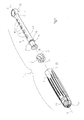
- number 1 indicates generally a friction damper extending longitudinally along an X-X axis.
- the damper 1 comprises a hollow cylindrical body 2, a rod 3 suitable to slidably engage the inside wall of said hollow body 2, and at least one braking or friction element 4 between the internal wall of the hollow cylindrical body and the external wall of the rod to provide the necessary frictional force.
- the hollow cylindrical body 2 includes a first closed end 21 on which is provided an anchoring element 22, such as a loop, suitable to fasten the damper 1 to a conventional cabinet or frame (not shown) of a laundry treatment machine.
- a second end 23 is open to engage the rod 3.
- the internal walls of the hollow cylindrical body 2 can be lined with a suitable layer of a material having a high resistance to wear, such as for example a metal foil or sleeve, such as a sheet of aluminium, which may be coated, or a film of thermoplastic polymeric material.
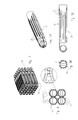
- the body 2 can have two diametrically opposite flat surfaces 24, and a plurality of ribs 25 protruding from the external surface of the body 2 included between said flat surfaces 24.
- the ribs 25 can be arranged at least in part diametrically staggered so as to create a dap joint or in any case a stacking arrangement (see enlarged detail in figure 6 ).
- said arrangement makes it possible, using two simple bands 26, to rapidly and safely fasten together a number of dampers in a compact manner.
- the dap joint arrangement becomes self-supporting and makes it possible to operate directly in the assembly lines in an automatic manner, facilitating the management and handling of the individual pieces and eliminating packaging and relative waste disposal.
- the rod 3 ( figure 1 ) includes a first closed end 31 on which is provided an anchoring element 32, for example a loop, for fastening to the tub of the machine, connected to a second end 33 that engages the cavity of the cylindrical body 2 through a middle portion 34.
- an anchoring element 32 for example a loop
- the rod 3 has a substantially cylindrical shape having an outside diameter smaller than the inside diameter of the hollow cylindrical body 2.
- the rod 3 shown in the figures has somewhat the shape of a truncated cone, with a smaller diameter at the end provided with the loop 32, thus also allowing small lateral oscillations of the rod with respect to the hollow cylindrical body.
- the middle portion 34 of the rod 3 can be provided with a plurality of openings 35, variously distributed, suitable to dissipate the heat that is generated during the alternating movement of the rod inside the hollow cylindrical body.
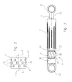
- the first end 33 of the rod 3 is provided with a seat 36 delimited by two flanges 37 or shoulders suitable to receive the friction element 4 coaxially to the rod.
- the flanges 37 are provided with pushing or abutting elements 38 facing the direction of the axis X-X, that operate on the friction element 4 and cause it to swell, as is better described hereunder.
- Said elements 38 can be in the form of projections shaped so as to act as pushing elements without damaging the friction element. In particular, they are distributed along the surface of the flange 37 turned toward the seat 36 that holds said friction element.
- the friction element 4 is preferably an annular band with a longitudinal axis Y-Y made, for example, of a polymeric material such as polyurethane foam, fitted onto said seat 36 and held there by means of the flanges 37.
- Said friction element 4 has an external annular contact surface 41 suitable to slidably cooperate with the inside surface of the hollow cylindrical body 2, and an internal annular contact surface 42 suitable to slidably cooperate with the external surface of the rod 3 in the seat 36 on said rod ( figure 1 ).
- the friction element 4 is provided with a plurality 43 of through holes on the wall of the element.
- the lubricant is drawn alternately toward one or the other shoulder 37 consequently to the oscillations transmitted by the movement of the drum in the laundry treatment machine.
- the holes 43 function as a kind of containers or reservoirs holding the lubricant.
- the holes once they are initially filled with lubricant, during the operation of the damper and as a result of the pressures applied on the friction element, release small quantities of lubricant in various areas of the friction element so that it can lubricate all the portions of the same. In this manner, the whole frictional surface is maintained suitably lubricated.
- the holes 43 work as a sort of pump that alternately releases and reabsorbs the lubricant.
- the part of the holes 43 positioned near the flange 37 closest to the loop 22 is subjected to compression by the pushing elements 38.
- This compression causes the expulsion of a certain quantity of lubricant.
- the holes 43 near the flange 37 farthest from the loop 22 are subjected to compression by the corresponding pushing elements 38.
- the holes 43 expand and suck in part of the lubricant previously released.
- the plurality of holes 43 is distributed in one or more annular rows R1, R2, as shown in figure 2 .
- the holes 43 in one row are axially staggered with respect to the holes 43 in the next row. It was found that this distribution of the holes makes it possible to further improve the distribution of the lubricant.
- the holes are staggered so that the tangential straight line in the axial direction of a hole in a row R1 coincides with the axially tangential straight line of the contiguous hole of the other row R2.
- the diameter of each hole must be equal to the distance between two contiguous holes. This last embodiment has proved to be best for an optimal distribution of lubricant, especially during an intense operation of the dampers.
- Both the rod 3 and the hollow cylindrical body 2 are conventionally made of a polymeric material of suitable firmness.
- the efficiency of the damper is maintained unaltered, thanks to the correct distribution of the lubricant.
- the arrangement of the pushing elements also makes it possible to increase the efficiency of the damper, as the oscillations are minimized by simply causing a swelling or expansion of the friction element.
- said friction damper 1 can be made simply and economically with the usual well-known systems, machines and equipment, while guaranteeing a reliable operation.
- shapes can be modified according to particular demands or preferences.
- the cross section of both the hollow body and of the rod can, for example, be square or rectangular, so that the friction element can be represented by a tampon applied on two opposite sides of the rod or fit by interference in a suitable slot to bulge from said opposite sides.
- the plastic materials with which the hollow body and the rod are made can be chosen from conventional plastics such as, for example, polyamide or polypropylene, possibly reinforced with mineral and/or natural or synthetic fibres.
- the friction element on the other hand, can be made of natural or synthetic rubber, preferably foamed, such as foam polyurethane, ethyl vinyl acetate (EVA).
- the materials forming the outside surface of the seat 36 of the rod 3 and the inside surface of the hollow cylindrical body 2 or its lining layer, or their surface roughness can be different, so as to vary the friction coefficients of the two surfaces, and thus the principle that governs the movement relative to each other of the two bodies having the friction element 1 interposed therebetween. In this manner, it is possible to more accurately calibrate the degree of the damping effect.
- the through holes 43 can be of any shape. In the figures, they are shown as having a circular shape, but they can also be oval, with the main axis disposed along to the X-X axis of the damper or transversal to it, or they may have a regular of irregular polygonal shape.
- friction damper described herein is preferably used in a laundry washing machine, it is understood that it can be used for different applications, as may be required.
Landscapes
- Engineering & Computer Science (AREA)
- General Engineering & Computer Science (AREA)
- Mechanical Engineering (AREA)
- Vibration Dampers (AREA)
Priority Applications (1)
| Application Number | Priority Date | Filing Date | Title |
|---|---|---|---|
| PL13151875T PL2618018T3 (pl) | 2012-01-23 | 2013-01-18 | Ulepszony amortyzator cierny |
Applications Claiming Priority (1)
| Application Number | Priority Date | Filing Date | Title |
|---|---|---|---|
| IT000004A ITPN20120004A1 (it) | 2012-01-23 | 2012-01-23 | Ammortizzatore frenante perfezionato |
Publications (3)
| Publication Number | Publication Date |
|---|---|
| EP2618018A1 true EP2618018A1 (de) | 2013-07-24 |
| EP2618018B1 EP2618018B1 (de) | 2020-08-26 |
| EP2618018B8 EP2618018B8 (de) | 2020-11-18 |
Family
ID=45955677
Family Applications (1)
| Application Number | Title | Priority Date | Filing Date |
|---|---|---|---|
| EP13151875.5A Active EP2618018B8 (de) | 2012-01-23 | 2013-01-18 | Verbesserter Reibungsdämpfer |
Country Status (3)
| Country | Link |
|---|---|
| EP (1) | EP2618018B8 (de) |
| IT (1) | ITPN20120004A1 (de) |
| PL (1) | PL2618018T3 (de) |
Citations (5)
| Publication number | Priority date | Publication date | Assignee | Title |
|---|---|---|---|---|
| US2562595A (en) * | 1946-04-22 | 1951-07-31 | Chrysler Corp | Shock absorber |
| GB1072286A (en) * | 1964-06-13 | 1967-06-14 | Jacques Georges Poyet | Improvements in or relating to motion damping devices |
| WO1995016813A1 (en) * | 1993-12-16 | 1995-06-22 | R. & D.S. S.R.L. | Shock absorber for washing machines, in particular household clothes washing machines |
| WO2000067851A2 (en) * | 1999-05-06 | 2000-11-16 | Lord Corporation | Controllable device having a matrix medium retaining structure |
| WO2005033399A1 (en) * | 2003-10-06 | 2005-04-14 | Lg Electronics, Inc. | Damper in a washing machine and fabricating method of the same |
-
2012
- 2012-01-23 IT IT000004A patent/ITPN20120004A1/it unknown
-
2013
- 2013-01-18 PL PL13151875T patent/PL2618018T3/pl unknown
- 2013-01-18 EP EP13151875.5A patent/EP2618018B8/de active Active
Patent Citations (5)
| Publication number | Priority date | Publication date | Assignee | Title |
|---|---|---|---|---|
| US2562595A (en) * | 1946-04-22 | 1951-07-31 | Chrysler Corp | Shock absorber |
| GB1072286A (en) * | 1964-06-13 | 1967-06-14 | Jacques Georges Poyet | Improvements in or relating to motion damping devices |
| WO1995016813A1 (en) * | 1993-12-16 | 1995-06-22 | R. & D.S. S.R.L. | Shock absorber for washing machines, in particular household clothes washing machines |
| WO2000067851A2 (en) * | 1999-05-06 | 2000-11-16 | Lord Corporation | Controllable device having a matrix medium retaining structure |
| WO2005033399A1 (en) * | 2003-10-06 | 2005-04-14 | Lg Electronics, Inc. | Damper in a washing machine and fabricating method of the same |
Also Published As
| Publication number | Publication date |
|---|---|
| ITPN20120004A1 (it) | 2013-07-24 |
| EP2618018B1 (de) | 2020-08-26 |
| EP2618018B8 (de) | 2020-11-18 |
| PL2618018T3 (pl) | 2021-04-19 |
Similar Documents
| Publication | Publication Date | Title |
|---|---|---|
| US6202806B1 (en) | Controllable device having a matrix medium retaining structure | |
| EP1025373B1 (de) | Vorrichtung mit regulierbarem medium und dieses benutzende einrichtung | |
| ES2431464B1 (es) | Amortiguador radial de vibraciones de recorrido libre, y aparato doméstico con un sistema de amortiguación que comprende dicho amortiguador radial | |
| US5813253A (en) | Arrangement for balancing of a body rotatable about an axis | |
| RU2613779C2 (ru) | Гаситель колебаний для бытового прибора с вращающимся барабаном и бытовой прибор с таким гасителем колебаний | |
| KR20110131197A (ko) | 헬리컬 랩 클러치 스프링 및 코일 댐퍼 스프링을 특징으로 하는 디커플러 | |
| KR20000057471A (ko) | 세척 장치용 마찰 댐퍼 | |
| KR101673725B1 (ko) | 개량형 마찰 요소를 구비한 쇼크 업소버 | |
| JP5096536B2 (ja) | 減衰装置 | |
| CN115667755B (zh) | 阻尼器组件和用于这种阻尼器组件的机器 | |
| EP2618018B1 (de) | Verbesserter Reibungsdämpfer | |
| CN107663741A (zh) | 悬挂减震系统和洗衣机 | |
| KR100856781B1 (ko) | 세탁기 | |
| US2879873A (en) | Speed limiting torque metering vibration dampening clutch | |
| EP2618017A1 (de) | Reibungsdämpfer mit verstellbaren Reibungsvorrichtungen | |
| CH649351A5 (it) | Cuscinetto radente a tacchetti oscillanti. | |
| CN206591300U (zh) | 波轮洗衣机及其吊杆组件 | |
| WO2015125075A1 (en) | Ventilated damper | |
| US6336533B1 (en) | Noise dampening brake shoe | |
| JP7008072B2 (ja) | ねじり減衰装置 | |
| RU2675472C1 (ru) | Вибродемпфирующее устройство, электрический бытовой прибор и способ изготовления такого устройства | |
| KR101285827B1 (ko) | 댐퍼 | |
| KR101178579B1 (ko) | 드럼세탁기용 전자석 현가댐퍼 | |
| KR101361415B1 (ko) | 댐퍼 플라이휠 | |
| JP2017086516A (ja) | 洗濯機 |
Legal Events
| Date | Code | Title | Description |
|---|---|---|---|
| PUAI | Public reference made under article 153(3) epc to a published international application that has entered the european phase |
Free format text: ORIGINAL CODE: 0009012 |
|
| AK | Designated contracting states |
Kind code of ref document: A1 Designated state(s): AL AT BE BG CH CY CZ DE DK EE ES FI FR GB GR HR HU IE IS IT LI LT LU LV MC MK MT NL NO PL PT RO RS SE SI SK SM TR |
|
| AX | Request for extension of the european patent |
Extension state: BA ME |
|
| 17P | Request for examination filed |
Effective date: 20140120 |
|
| RBV | Designated contracting states (corrected) |
Designated state(s): AL AT BE BG CH CY CZ DE DK EE ES FI FR GB GR HR HU IE IS IT LI LT LU LV MC MK MT NL NO PL PT RO RS SE SI SK SM TR |
|
| STAA | Information on the status of an ep patent application or granted ep patent |
Free format text: STATUS: EXAMINATION IS IN PROGRESS |
|
| 17Q | First examination report despatched |
Effective date: 20190520 |
|
| GRAP | Despatch of communication of intention to grant a patent |
Free format text: ORIGINAL CODE: EPIDOSNIGR1 |
|
| STAA | Information on the status of an ep patent application or granted ep patent |
Free format text: STATUS: GRANT OF PATENT IS INTENDED |
|
| INTG | Intention to grant announced |
Effective date: 20200520 |
|
| GRAS | Grant fee paid |
Free format text: ORIGINAL CODE: EPIDOSNIGR3 |
|
| GRAA | (expected) grant |
Free format text: ORIGINAL CODE: 0009210 |
|
| STAA | Information on the status of an ep patent application or granted ep patent |
Free format text: STATUS: THE PATENT HAS BEEN GRANTED |
|
| AK | Designated contracting states |
Kind code of ref document: B1 Designated state(s): AL AT BE BG CH CY CZ DE DK EE ES FI FR GB GR HR HU IE IS IT LI LT LU LV MC MK MT NL NO PL PT RO RS SE SI SK SM TR |
|
| REG | Reference to a national code |
Ref country code: GB Ref legal event code: FG4D |
|
| REG | Reference to a national code |
Ref country code: CH Ref legal event code: EP |
|
| REG | Reference to a national code |
Ref country code: DE Ref legal event code: R096 Ref document number: 602013071906 Country of ref document: DE |
|
| REG | Reference to a national code |
Ref country code: AT Ref legal event code: REF Ref document number: 1306671 Country of ref document: AT Kind code of ref document: T Effective date: 20200915 |
|
| REG | Reference to a national code |
Ref country code: IE Ref legal event code: FG4D |
|
| REG | Reference to a national code |
Ref country code: DE Ref legal event code: R081 Ref document number: 602013071906 Country of ref document: DE Owner name: ROSA PLAST S.R.L., PORCIA, IT Free format text: FORMER OWNER: RO-SA PLAST S.P.A., PORCIA, PORDENONE, IT |
|
| RAP2 | Party data changed (patent owner data changed or rights of a patent transferred) |
Owner name: ROSA PLAST S.R.L. |
|
| REG | Reference to a national code |
Ref country code: CH Ref legal event code: PK Free format text: BERICHTIGUNG B8 |
|
| REG | Reference to a national code |
Ref country code: LT Ref legal event code: MG4D |
|
| PG25 | Lapsed in a contracting state [announced via postgrant information from national office to epo] |
Ref country code: SE Free format text: LAPSE BECAUSE OF FAILURE TO SUBMIT A TRANSLATION OF THE DESCRIPTION OR TO PAY THE FEE WITHIN THE PRESCRIBED TIME-LIMIT Effective date: 20200826 Ref country code: PT Free format text: LAPSE BECAUSE OF FAILURE TO SUBMIT A TRANSLATION OF THE DESCRIPTION OR TO PAY THE FEE WITHIN THE PRESCRIBED TIME-LIMIT Effective date: 20201228 Ref country code: FI Free format text: LAPSE BECAUSE OF FAILURE TO SUBMIT A TRANSLATION OF THE DESCRIPTION OR TO PAY THE FEE WITHIN THE PRESCRIBED TIME-LIMIT Effective date: 20200826 Ref country code: GR Free format text: LAPSE BECAUSE OF FAILURE TO SUBMIT A TRANSLATION OF THE DESCRIPTION OR TO PAY THE FEE WITHIN THE PRESCRIBED TIME-LIMIT Effective date: 20201127 Ref country code: LT Free format text: LAPSE BECAUSE OF FAILURE TO SUBMIT A TRANSLATION OF THE DESCRIPTION OR TO PAY THE FEE WITHIN THE PRESCRIBED TIME-LIMIT Effective date: 20200826 Ref country code: HR Free format text: LAPSE BECAUSE OF FAILURE TO SUBMIT A TRANSLATION OF THE DESCRIPTION OR TO PAY THE FEE WITHIN THE PRESCRIBED TIME-LIMIT Effective date: 20200826 Ref country code: BG Free format text: LAPSE BECAUSE OF FAILURE TO SUBMIT A TRANSLATION OF THE DESCRIPTION OR TO PAY THE FEE WITHIN THE PRESCRIBED TIME-LIMIT Effective date: 20201126 Ref country code: NO Free format text: LAPSE BECAUSE OF FAILURE TO SUBMIT A TRANSLATION OF THE DESCRIPTION OR TO PAY THE FEE WITHIN THE PRESCRIBED TIME-LIMIT Effective date: 20201126 |
|
| REG | Reference to a national code |
Ref country code: NL Ref legal event code: MP Effective date: 20200826 |
|
| REG | Reference to a national code |
Ref country code: AT Ref legal event code: MK05 Ref document number: 1306671 Country of ref document: AT Kind code of ref document: T Effective date: 20200826 |
|
| PG25 | Lapsed in a contracting state [announced via postgrant information from national office to epo] |
Ref country code: IS Free format text: LAPSE BECAUSE OF FAILURE TO SUBMIT A TRANSLATION OF THE DESCRIPTION OR TO PAY THE FEE WITHIN THE PRESCRIBED TIME-LIMIT Effective date: 20201226 Ref country code: RS Free format text: LAPSE BECAUSE OF FAILURE TO SUBMIT A TRANSLATION OF THE DESCRIPTION OR TO PAY THE FEE WITHIN THE PRESCRIBED TIME-LIMIT Effective date: 20200826 Ref country code: LV Free format text: LAPSE BECAUSE OF FAILURE TO SUBMIT A TRANSLATION OF THE DESCRIPTION OR TO PAY THE FEE WITHIN THE PRESCRIBED TIME-LIMIT Effective date: 20200826 Ref country code: NL Free format text: LAPSE BECAUSE OF FAILURE TO SUBMIT A TRANSLATION OF THE DESCRIPTION OR TO PAY THE FEE WITHIN THE PRESCRIBED TIME-LIMIT Effective date: 20200826 |
|
| PG25 | Lapsed in a contracting state [announced via postgrant information from national office to epo] |
Ref country code: RO Free format text: LAPSE BECAUSE OF FAILURE TO SUBMIT A TRANSLATION OF THE DESCRIPTION OR TO PAY THE FEE WITHIN THE PRESCRIBED TIME-LIMIT Effective date: 20200826 Ref country code: SM Free format text: LAPSE BECAUSE OF FAILURE TO SUBMIT A TRANSLATION OF THE DESCRIPTION OR TO PAY THE FEE WITHIN THE PRESCRIBED TIME-LIMIT Effective date: 20200826 Ref country code: EE Free format text: LAPSE BECAUSE OF FAILURE TO SUBMIT A TRANSLATION OF THE DESCRIPTION OR TO PAY THE FEE WITHIN THE PRESCRIBED TIME-LIMIT Effective date: 20200826 Ref country code: DK Free format text: LAPSE BECAUSE OF FAILURE TO SUBMIT A TRANSLATION OF THE DESCRIPTION OR TO PAY THE FEE WITHIN THE PRESCRIBED TIME-LIMIT Effective date: 20200826 Ref country code: CZ Free format text: LAPSE BECAUSE OF FAILURE TO SUBMIT A TRANSLATION OF THE DESCRIPTION OR TO PAY THE FEE WITHIN THE PRESCRIBED TIME-LIMIT Effective date: 20200826 |
|
| REG | Reference to a national code |
Ref country code: DE Ref legal event code: R097 Ref document number: 602013071906 Country of ref document: DE |
|
| PG25 | Lapsed in a contracting state [announced via postgrant information from national office to epo] |
Ref country code: ES Free format text: LAPSE BECAUSE OF FAILURE TO SUBMIT A TRANSLATION OF THE DESCRIPTION OR TO PAY THE FEE WITHIN THE PRESCRIBED TIME-LIMIT Effective date: 20200826 Ref country code: AL Free format text: LAPSE BECAUSE OF FAILURE TO SUBMIT A TRANSLATION OF THE DESCRIPTION OR TO PAY THE FEE WITHIN THE PRESCRIBED TIME-LIMIT Effective date: 20200826 Ref country code: AT Free format text: LAPSE BECAUSE OF FAILURE TO SUBMIT A TRANSLATION OF THE DESCRIPTION OR TO PAY THE FEE WITHIN THE PRESCRIBED TIME-LIMIT Effective date: 20200826 |
|
| PG25 | Lapsed in a contracting state [announced via postgrant information from national office to epo] |
Ref country code: SK Free format text: LAPSE BECAUSE OF FAILURE TO SUBMIT A TRANSLATION OF THE DESCRIPTION OR TO PAY THE FEE WITHIN THE PRESCRIBED TIME-LIMIT Effective date: 20200826 |
|
| PLBE | No opposition filed within time limit |
Free format text: ORIGINAL CODE: 0009261 |
|
| STAA | Information on the status of an ep patent application or granted ep patent |
Free format text: STATUS: NO OPPOSITION FILED WITHIN TIME LIMIT |
|
| 26N | No opposition filed |
Effective date: 20210527 |
|
| PG25 | Lapsed in a contracting state [announced via postgrant information from national office to epo] |
Ref country code: SI Free format text: LAPSE BECAUSE OF FAILURE TO SUBMIT A TRANSLATION OF THE DESCRIPTION OR TO PAY THE FEE WITHIN THE PRESCRIBED TIME-LIMIT Effective date: 20200826 Ref country code: MC Free format text: LAPSE BECAUSE OF FAILURE TO SUBMIT A TRANSLATION OF THE DESCRIPTION OR TO PAY THE FEE WITHIN THE PRESCRIBED TIME-LIMIT Effective date: 20200826 |
|
| REG | Reference to a national code |
Ref country code: CH Ref legal event code: PL |
|
| GBPC | Gb: european patent ceased through non-payment of renewal fee |
Effective date: 20210118 |
|
| PG25 | Lapsed in a contracting state [announced via postgrant information from national office to epo] |
Ref country code: LU Free format text: LAPSE BECAUSE OF NON-PAYMENT OF DUE FEES Effective date: 20210118 |
|
| REG | Reference to a national code |
Ref country code: BE Ref legal event code: MM Effective date: 20210131 |
|
| PG25 | Lapsed in a contracting state [announced via postgrant information from national office to epo] |
Ref country code: FR Free format text: LAPSE BECAUSE OF NON-PAYMENT OF DUE FEES Effective date: 20210131 |
|
| PG25 | Lapsed in a contracting state [announced via postgrant information from national office to epo] |
Ref country code: LI Free format text: LAPSE BECAUSE OF NON-PAYMENT OF DUE FEES Effective date: 20210131 Ref country code: CH Free format text: LAPSE BECAUSE OF NON-PAYMENT OF DUE FEES Effective date: 20210131 Ref country code: GB Free format text: LAPSE BECAUSE OF NON-PAYMENT OF DUE FEES Effective date: 20210118 |
|
| PG25 | Lapsed in a contracting state [announced via postgrant information from national office to epo] |
Ref country code: IE Free format text: LAPSE BECAUSE OF NON-PAYMENT OF DUE FEES Effective date: 20210118 |
|
| PG25 | Lapsed in a contracting state [announced via postgrant information from national office to epo] |
Ref country code: IS Free format text: LAPSE BECAUSE OF FAILURE TO SUBMIT A TRANSLATION OF THE DESCRIPTION OR TO PAY THE FEE WITHIN THE PRESCRIBED TIME-LIMIT Effective date: 20201226 |
|
| PG25 | Lapsed in a contracting state [announced via postgrant information from national office to epo] |
Ref country code: BE Free format text: LAPSE BECAUSE OF NON-PAYMENT OF DUE FEES Effective date: 20210131 |
|
| PG25 | Lapsed in a contracting state [announced via postgrant information from national office to epo] |
Ref country code: HU Free format text: LAPSE BECAUSE OF FAILURE TO SUBMIT A TRANSLATION OF THE DESCRIPTION OR TO PAY THE FEE WITHIN THE PRESCRIBED TIME-LIMIT; INVALID AB INITIO Effective date: 20130118 |
|
| P01 | Opt-out of the competence of the unified patent court (upc) registered |
Effective date: 20230508 |
|
| PG25 | Lapsed in a contracting state [announced via postgrant information from national office to epo] |
Ref country code: CY Free format text: LAPSE BECAUSE OF FAILURE TO SUBMIT A TRANSLATION OF THE DESCRIPTION OR TO PAY THE FEE WITHIN THE PRESCRIBED TIME-LIMIT Effective date: 20200826 |
|
| PG25 | Lapsed in a contracting state [announced via postgrant information from national office to epo] |
Ref country code: MK Free format text: LAPSE BECAUSE OF FAILURE TO SUBMIT A TRANSLATION OF THE DESCRIPTION OR TO PAY THE FEE WITHIN THE PRESCRIBED TIME-LIMIT Effective date: 20200826 |
|
| PG25 | Lapsed in a contracting state [announced via postgrant information from national office to epo] |
Ref country code: MT Free format text: LAPSE BECAUSE OF FAILURE TO SUBMIT A TRANSLATION OF THE DESCRIPTION OR TO PAY THE FEE WITHIN THE PRESCRIBED TIME-LIMIT Effective date: 20200826 |
|
| PGFP | Annual fee paid to national office [announced via postgrant information from national office to epo] |
Ref country code: PL Payment date: 20251222 Year of fee payment: 14 |
|
| PGFP | Annual fee paid to national office [announced via postgrant information from national office to epo] |
Ref country code: DE Payment date: 20260121 Year of fee payment: 14 |
|
| PGFP | Annual fee paid to national office [announced via postgrant information from national office to epo] |
Ref country code: IT Payment date: 20260109 Year of fee payment: 14 |
|
| PGFP | Annual fee paid to national office [announced via postgrant information from national office to epo] |
Ref country code: TR Payment date: 20260115 Year of fee payment: 14 |