EP2618071A2 - Accumulateur stratifié - Google Patents
Accumulateur stratifié Download PDFInfo
- Publication number
- EP2618071A2 EP2618071A2 EP13151773.2A EP13151773A EP2618071A2 EP 2618071 A2 EP2618071 A2 EP 2618071A2 EP 13151773 A EP13151773 A EP 13151773A EP 2618071 A2 EP2618071 A2 EP 2618071A2
- Authority
- EP
- European Patent Office
- Prior art keywords
- chamber
- discharge
- feed
- openings
- heat transfer
- Prior art date
- Legal status (The legal status is an assumption and is not a legal conclusion. Google has not performed a legal analysis and makes no representation as to the accuracy of the status listed.)
- Withdrawn
Links
Images


Classifications
-
- F—MECHANICAL ENGINEERING; LIGHTING; HEATING; WEAPONS; BLASTING
- F24—HEATING; RANGES; VENTILATING
- F24D—DOMESTIC- OR SPACE-HEATING SYSTEMS, e.g. CENTRAL HEATING SYSTEMS; DOMESTIC HOT-WATER SUPPLY SYSTEMS; ELEMENTS OR COMPONENTS THEREFOR
- F24D11/00—Central heating systems using heat accumulated in storage masses
- F24D11/002—Central heating systems using heat accumulated in storage masses water heating system
-
- F—MECHANICAL ENGINEERING; LIGHTING; HEATING; WEAPONS; BLASTING
- F24—HEATING; RANGES; VENTILATING
- F24H—FLUID HEATERS, e.g. WATER OR AIR HEATERS, HAVING HEAT-GENERATING MEANS, e.g. HEAT PUMPS, IN GENERAL
- F24H9/00—Details
- F24H9/12—Arrangements for connecting heaters to circulation pipes
- F24H9/13—Arrangements for connecting heaters to circulation pipes for water heaters
- F24H9/133—Storage heaters
-
- F—MECHANICAL ENGINEERING; LIGHTING; HEATING; WEAPONS; BLASTING
- F28—HEAT EXCHANGE IN GENERAL
- F28D—HEAT-EXCHANGE APPARATUS, NOT PROVIDED FOR IN ANOTHER SUBCLASS, IN WHICH THE HEAT-EXCHANGE MEDIA DO NOT COME INTO DIRECT CONTACT
- F28D20/00—Heat storage plants or apparatus in general; Regenerative heat-exchange apparatus not covered by groups F28D17/00 or F28D19/00
- F28D20/0034—Heat storage plants or apparatus in general; Regenerative heat-exchange apparatus not covered by groups F28D17/00 or F28D19/00 using liquid heat storage material
- F28D20/0039—Heat storage plants or apparatus in general; Regenerative heat-exchange apparatus not covered by groups F28D17/00 or F28D19/00 using liquid heat storage material with stratification of the heat storage material
-
- F—MECHANICAL ENGINEERING; LIGHTING; HEATING; WEAPONS; BLASTING
- F28—HEAT EXCHANGE IN GENERAL
- F28D—HEAT-EXCHANGE APPARATUS, NOT PROVIDED FOR IN ANOTHER SUBCLASS, IN WHICH THE HEAT-EXCHANGE MEDIA DO NOT COME INTO DIRECT CONTACT
- F28D20/00—Heat storage plants or apparatus in general; Regenerative heat-exchange apparatus not covered by groups F28D17/00 or F28D19/00
- F28D2020/0065—Details, e.g. particular heat storage tanks, auxiliary members within tanks
- F28D2020/0069—Distributing arrangements; Fluid deflecting means
-
- F—MECHANICAL ENGINEERING; LIGHTING; HEATING; WEAPONS; BLASTING
- F28—HEAT EXCHANGE IN GENERAL
- F28D—HEAT-EXCHANGE APPARATUS, NOT PROVIDED FOR IN ANOTHER SUBCLASS, IN WHICH THE HEAT-EXCHANGE MEDIA DO NOT COME INTO DIRECT CONTACT
- F28D20/00—Heat storage plants or apparatus in general; Regenerative heat-exchange apparatus not covered by groups F28D17/00 or F28D19/00
- F28D2020/0065—Details, e.g. particular heat storage tanks, auxiliary members within tanks
- F28D2020/0086—Partitions
-
- Y—GENERAL TAGGING OF NEW TECHNOLOGICAL DEVELOPMENTS; GENERAL TAGGING OF CROSS-SECTIONAL TECHNOLOGIES SPANNING OVER SEVERAL SECTIONS OF THE IPC; TECHNICAL SUBJECTS COVERED BY FORMER USPC CROSS-REFERENCE ART COLLECTIONS [XRACs] AND DIGESTS
- Y02—TECHNOLOGIES OR APPLICATIONS FOR MITIGATION OR ADAPTATION AGAINST CLIMATE CHANGE
- Y02E—REDUCTION OF GREENHOUSE GAS [GHG] EMISSIONS, RELATED TO ENERGY GENERATION, TRANSMISSION OR DISTRIBUTION
- Y02E60/00—Enabling technologies; Technologies with a potential or indirect contribution to GHG emissions mitigation
- Y02E60/14—Thermal energy storage
Definitions
- the invention relates to a stratified storage device for storing heat energy, comprising a layer insert and a storage container, which is connected by means of pipelines to at least one energy generator and at least one energy consumer and at least two supply ports and two discharge openings, wherein at least one supply port to the power generator and at least one supply port connected to the energy consumer and at least one discharge opening with the power generator and at least one discharge opening with the energy consumer, wherein by means of the feed openings the stratified storage a heat transfer medium can be supplied and by means of the discharge openings the heat transfer medium from the stratified storage, the stratified storage a feed chamber, a settling chamber and having a discharge chamber, which are arranged side by side viewed in the horizontal direction and each fondrec vertically ken, wherein the at least two supply openings with the supply chamber and the at least two discharge openings correspond to the discharge chamber, wherein the supply chamber, the settling chamber and the discharge chamber are connected in series in a flow direction of the heat transfer medium, starting from a respective feed opening towards a respective
- the stratified storage tank solves this problem by a temperature-dependent stratification of the water within the water storage by mixing of the water supply is prevented.
- the layering itself does not have to be created artificially, but rather forms automatically due to the different densities of the water as a function of the temperature. Specifically, this means that warm water is lighter than cold water and therefore a still amount of water forms a natural stratification from cold (down) to warm (up).
- the development of the stratified storage tanks is therefore primarily concerned with the problem of introducing water into the stratified storage tank without "destroying" the natural stratification.
- the difficulty with the operation of a stratified storage is that the natural stratification of the water takes a relatively long time and can easily be disturbed by flows with a vertical flow component. Such a disturbance manifests itself in a mixing of layers of different temperature, which leads directly to a cooling of the respective warmer layer, which is accordingly no longer available at the original temperature level.
- a storage container having a centrally arranged riser, which is provided at different height levels with openings which are separated by means of folding elements hydraulically from the stratified storage.
- the riser serves as a supply line for heated by a heat generator water in the memory.
- the water conducted by the heat generator in the riser water can flow only at that level from a respective opening in the storage container on which the surrounding water has the same or a smaller density than that in the riser rising water.
- Another layer store is the DE 44 17 138 C2 removable.
- This also has a centrally disposed tubular element, which is divided by a vertical wall into two parts, a flow chamber and a return chamber. These two chambers are further subdivided by means of further respective internals in inflow and settling chambers.
- This stratified storage tank is based on the principle that hot water is only supplied to the storage tank when hot water is not being withdrawn. In the case of high energy consumption (for example, high demand of heat at the radiator stations), the water supplied from the power generator to the reservoir is drawn directly from the flow chamber and fed to the radiators. This is called a "short-circuit flow".
- a "boot” of stratified storage with warm Water that is, a supply of warm water, but a failure to remove the same, takes place accordingly only when no high consumption of warm water is present.
- the water flowing from the energy generator into the reservoir is decelerated by the arrangement of the partition walls explained, so that it can pass as free from turbulence as possible from the central tube element into the surrounding stratified storage.
- a turbulence-poor introduction of the water in the surrounding memory is possible, a mixing of the water already in the flow chamber is not prevented in the apparatus shown.
- Another arrangement shows the DE 101 23 305 A 1 , which describes a stratified storage of the type described above, wherein the supply chamber and the settling chamber - similar to the aforementioned memory - are formed in a centrally disposed tubular element, which is surrounded by the discharge chamber.
- the supply chamber is provided with a plurality of supply lines, which are arranged at different height levels and in this way already take into account the expected water temperature of the guided through them in the memory water.
- the memory shown has the particular disadvantage that the individual mass flows of different temperature flowing into the feed chamber are already mixed in the feed chamber. Another disadvantage of the memory shown is the potentially short flow path of the water within the storage container.
- the invention is therefore based on the object to produce a stratified storage, in which a thorough mixing of the different temperature layers is largely avoided.
- the underlying object is based on a stratified storage of the type described above, according to the invention, that the feed chamber is divided by means of at least one horizontally oriented bulkhead element in an upper and a lower Zuzhou screeningsetation, preferably by means of a plurality of horizontally oriented bulkhead elements in a plurality of vertically stacked Zunatural screeningsetationen wherein the individual Zuindustrial screeningsetationen are preferably hydraulically connected to each other.
- the terms supply chamber and discharge chamber are to be understood as meaning that preferably all mass flows entering the stratified storage tank enter the supply chamber through the supply openings and more preferably all mass flows discharged from the stratified storage tank exit through the discharge openings from the discharge chamber. An exception to this is the removal of warm water to heat drinking water, which should be removed from the comfort chamber advantageously. This embodiment of the layer memory will be explained separately later.
- the subdivision of the feed chamber into individual sections results in water introduced into the stratified storage being prevented from mixing with other water layers as early as when it is introduced into the store.
- the at least two feed openings are typically arranged in each case at different height levels, since water currents of different temperature are supplied to the stratified storage tank through them. For example, while a flow of a boiler has a temperature of 80 ° C, the return temperature from the radiator, for example, 50 ° C.
- the two feed openings should correspond to different feed chamber sections, which form separate spaces within the feed chamber by means of the bulkhead element according to the invention. In this way, mixing of the differently tempered water streams can be avoided particularly effectively.
- the subdivision of the feed chamber into individual feed chamber sections also offers the advantage that the incoming feed streams of the water entering through the feed openings are locally "braked".
- the entering water flows therefore remain locally limited due to the bulkhead elements not only in their mixing effect but are also braked by the bulkhead elements and are calmed in this way particularly quickly.
- the temperature of the heating return is considerably above 50 ° C, for example because the radiators hardly withdraw heat from the heating water due to a low temperature gradient between the radiators and the room to be heated and the water at 60 ° C instead of typical 50 ° C flows into the feed chamber.
- the warm water in the associated feed chamber section would heat the already existing water and in this way reduce its density, thereby endeavoring to ascend.
- the individual feed chamber sections are hydraulically separated from one another, it would even be conceivable that an upper section with colder water would be arranged above such a section with warmer water.
- the Zunaturalschsetationen are hydraulically connected to each other by means of at least one tubular exchange element, wherein the exchange element preferably extends over an entire height of the feed chamber.
- the exchange of different warm water is particularly easy by means of such exchange element possible.
- This may have the shape of a tube and be provided with openings over its entire height, each opening into the different feed chamber sections.
- a typical embodiment of the stratified storage device provides, in addition to the at least two feed openings, further feed openings which are connected to different energy generators (for example a heat pump or a solar system) and / or different energy consumers (for example drinking water and / or underfloor heating).
- the feed openings should thereby advantageously correspond to different feed chamber sections, that is to say be arranged vertically offset within the feed chamber, so that the water introduced through them into the feed chamber flows directly at such a height into the feed chamber, which is presumably the temperature of the water layer of the stratified store arranged at this height equivalent. That is, the higher the prospective temperature of the water introduced through it into the feed chamber, the higher the feed openings should be arranged in a higher feed chamber section. Consequently, returns from energy consumers are typically located lower in the feed chamber than the headers of the energy producers.
- At least one closed delay element is arranged in the feed chamber into which at least one feed opening opens, wherein a wall of the delay element has a plurality of openings through which the heat transfer medium starting from the respective feed opening into the respective Zuzhoucrosetation can be conducted, wherein in the case of multiple feed openings preferably each feed opening has its own delay element.
- Such delay elements cause the liquid flow introduced through the feed openings into the feed chamber section to be throttled directly in its velocity, thus minimizing the mixing effect of the liquid flow. In this way it can even be achieved that forms a stable stratification within a Zubuchschetechnisch, which is disturbed only minimally by the inflowing water of the feed ports.
- such a discharge chamber is particularly advantageous, which has a plurality of vertically offset discharge openings, which correspond in each case with the discharge chamber. Since the water in the stratified storage is in layers of different temperature, it is possible by means of a clever placement of the discharge openings to remove just that water which has the desired temperature.
- a heating flow which is connected to normal surface heaters, advantageously to be arranged in an upper region of the discharge chamber, since in the upper part of high-temperature water is located.
- power generators should rather be arranged in a lower area of the discharge chamber and remove cold water from the stratified storage tank.
- the removal of the cold water by means of the discharge opening eventually leads to a local flow, which is directed to the discharge opening.
- the water flows the Abriosö réelle only from a horizontal layer, which is arranged at the same height on which the discharge opening is located.
- the flow pattern will be adjusted so that the discharge opening also flows in such water, which is located above the discharge opening, that is, has a higher temperature.
- This entails the effect of forming a vertical flow within the purge chamber, which becomes stronger the higher the flow rate through the energy generator is set. The consequence of this is an undesirable mixing of different temperature levels within the discharge chamber.
- the bulkhead element according to the invention which divides the discharge chamber, this can be prevented because the vertical flow is cut off by the bulkhead elements.
- Another way to reduce the formation of a pronounced, the stratification of the memory impairing flow pattern in the course of the removal of the heat transfer medium from the stratified storage is to divide the discharge chamber by means of a vertically oriented tubular element, wherein the tubular element, the discharge chamber into a Abvantvorhunt and a Divided discharge main chamber and a shell of the tubular element has a plurality of distributed over the height openings through which the heat transfer medium from the Abvantvorhunt in the Ab technologicalhaupthunt is conductive, viewed in the direction of flow of the heat transfer medium Ab2020maschinefit preferably the Abvantvorhunt and preferably the at least two discharge openings in the Abvantmaschinetting are arranged.
- such a discharge main chamber is particularly advantageous, comprising a horizontally oriented bulkhead member dividing the discharge main chamber into upper and lower discharge main chamber sections and preferably fluid-tightly separating the upper discharge main chamber section from the lower main discharge chamber section, preferably at least one discharge opening with the lower discharge main chamber Ab technologicalmaschinechtsetation and at least one further discharge opening with the upper Abtechnologymaschineppsetation correspond.
- a layer memory in which the separating elements and / or the at least one bulkhead element and / or the pipes made of plastic, in particular hard PVC, and / or made of plastic-coated material, in particular plastic-coated sheet metal.
- the plastic is particularly preferable because it conducts the heat of the water particularly bad.
- vertically extending in the stratified storage components should be made of such material, so that a heat transfer from a warm upper water layer to a cold lower water layer along these components is minimized.
- rigid PVC the use of polypropylene or other plastics is also conceivable.
- both the supply chamber and the discharge chamber viewed from a base element of the layer insert, have a lower height than the settling chamber.
- the feed chamber is essentially the intermixing of the stratification of the
- the discharge chamber is provided in particular to minimize mixing of the layers in the course of removal of water from the stratified storage.
- the calming chamber serves as a central chamber between the feed and the discharge chamber and represents a distance to be overcome for the water within the stratified storage since each water particle must flow through the settling chamber before exiting the stratified storage. Since no lines correspond directly to the settling chamber, it is not exposed to turbulent flows and thus forms the "quietest" chamber of the stratified storage. In her the formation of the temperature layers is particularly undisturbed and particularly pronounced.
- the uppermost warmest layer of the stratified storage can be made particularly large, so that there is always sufficient water at the highest temperature available. If this were not the case, the "warmest layer” would immediately grow down over a top feed chamber section and be continually cooled by cooler water flowing into a feed chamber section located below the top feed chamber section, resulting in energy loss.
- the settling chamber extends in an upper portion of the stratified storage over an entire horizontally guided cross-section of the storage container.
- the supply chamber and the discharge chamber are each separated at an upper end by means of a horizontally oriented ceiling element of the settling chamber.
- a vertical flow of the heat transfer medium between the uppermost ZuWORKschreibsetation or an upper portion of the discharge chamber and the upper portion of the settling chamber is prevented, so that the water must always flow through the openings of the separating elements to move from the feed chamber into the settling chamber or from the Settling chamber to get into the discharge chamber.
- a discharge opening which corresponds to the settling chamber and is preferably arranged in an upper region of the settling chamber.
- this discharge opening is the opening which serves to supply DHW with warm water.
- the discharge opening is arranged in the upper region of the settling chamber, advantageously above the discharge chamber, it corresponds exclusively to the warmest layer in the stratified storage. Since the removal of warm water for the heating of drinking water is only very occasionally, but required in significant quantities, the connection of the associated discharge opening to the calming chamber is particularly useful because the calming chamber has a large flow cross section, which causes even during removal a large amount of water, no high flow velocities occur within the stratified storage.
- the underlying object is further achieved starting from a stratified storage of the type described above, characterized in that the supply chamber, the settling chamber and the discharge chamber each adjacent to an outer jacket of the storage container.
- This type of arrangement of the individual chambers means that a flow path of the water from the feed chamber to the discharge chamber is as long as possible, so that the water has sufficient time available to form a stratification. Short circuits between a supply port and a discharge port, as are potentially possible in the prior art, can be prevented in this way because the water is forced to travel a long way.
- the chambers should be arranged on that of the storage container so that the supply chamber and the discharge chamber "face each other", that is, both chambers are arranged on opposite sides of the settling chamber. In this way it is ensured that the flow path from a feed opening to a discharge opening is maximum.
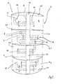
- FIG. 1 a supply chamber 2 of a layer insert 1 of a stratified storage device according to the invention is shown, which is subdivided into four supply chamber sections 4 by means of three bulkhead elements 3.
- the bulkhead elements 3 are horizontally oriented and rounded along an edge 5, so that they are adapted as well as possible to a cylindrical shell, not shown, of a storage container.
- This separating element 6 is provided with openings 8 distributed over its height, which provide a connection between the feed chamber 2 and the individual feed chamber sections 4 and the settling chamber 7.
- the supply chamber 2 on supply ports 9, which are each connected to pipes.
- an uppermost feed opening 9 ' is connected by means of a pipeline to a flow of a condensing boiler, while a lower feed opening 9 "corresponds to a return of a domestic water heating system.
- the respective supply opening 9, through which the heat transfer medium should flow into the supply chamber 2 should be arranged in a higher range of the supply chamber 2.
- All feed openings 9 are connected in the feed chamber 2 by means of a respective inlet tube 10 with a delay element 11, so that flows of a heat transfer medium, which are passed through the feed openings 9 in the stratified storage, always first a respective delay element 11 must flow through before they in a respective Zuzhou screeningsetation 4 can pass.
- the delay element 11 is a tubular element which has openings 12 through which the heat transfer medium can pass. The arrangement of both the inlet tubes 10 and the delay elements 11 is chosen so that the stratified storage heat transfer medium must be deflected as often as possible before it flows into the feed chamber 2.
- the latter effect of the low mixing of adjoining temperature layers of the heat transfer medium is particularly favored by the arrangement of the bulkhead elements 3 according to the invention. Namely, these cause a locally introduced into a Zuzhouschreibsetation 4 stream of heat transfer medium is prevented therein, a temperature stratification in the remaining Zuzhouschreibsetationen. 4 prevails to influence negatively.
- the Schott elements 3 act positively with respect to a further deceleration of the entering into the stratified storage flow of the heat transfer medium, so that in a transfer of the same from a respective Zuzhouschschschschetechnisch 4 in the settling chamber 7, the flow velocity has already decreased and the temperature stratification of the heat transfer medium in the settling chamber. 7 not to disturb.
- the feed chamber 2 is bounded at a lower end by a bottom element 14 of the layer insert and at an upper end by a ceiling element 15.
- FIG. 2 shows the same embodiment in such a perspective, showing both the supply chamber 2, and the settling chamber 7. Furthermore, in the perspective shown on a right side, a discharge chamber 16 is arranged, which will be explained later in more detail.
- the settling chamber 7 has a deflection element 17, which has a shape of half a tubular element.
- This deflecting element 17 is viewed over its height as well as the separating element 6 is provided with openings 18.
- These openings 18 are arranged such that a flow of the heat transfer medium flowing from the supply chamber sections 4 into the settling chamber 7 has to be deflected within the deflecting element 17 in order to pass from the openings 8 of the separating element 6 to the openings 18 of the deflecting element 17.
- This deflection again causes a calming of the flow of the heat transfer medium, which in turn reduces a mixing of the temperature layers.
- a further deflecting element 20 is arranged on a separating element 19 which separates the settling chamber 7 from the discharge chamber 16, which, like the deflecting element 17, the Has the shape of a half pipe element.
- the deflecting element 20 also also has openings which allow passage of the heat transfer medium from the settling chamber 7 into the deflecting element 20. These openings, in FIG. 2 are not recognizable, are arranged analogously to the deflection element 17 over an entire height of the deflecting element 20. The openings are arranged on a side facing away from the openings 18 of the deflecting 17 side of the deflecting element 20.
- the openings 18 of the deflecting element 17 and the openings of the deflecting element 20 consequently have, so to speak, different directions.
- This has the background that the heat transfer medium flowing through the stratified storage tank has to travel as long as possible on its way from the supply chamber 2 to the discharge chamber 16 in this way, and furthermore a flow direction of the heat transfer medium has to be changed several times. In this way, high flow rates, which are always associated with the risk of mixing and thus destruction of the temperature stratification, largely prevented.
- the settling chamber 7 has a greater height than the feed chamber 2 and the discharge chamber 16, wherein the layer insert 1 is surrounded in an operating state of the jacket of the storage container, which projects beyond the feed chamber 2 and the discharge chamber 16 by a certain amount.
- an upper area of the stratified storage here is arranged above the ceiling element 15 of the feed chamber 2, a total horizontally guided cross-section is formed by the stratified storage of the settling chamber 7 accordingly. In this way, it is possible to maintain a particularly large amount of warm water in the settling chamber 7, which can be used at any time in the operating state.
- the deflecting elements 17, 20 are here as well as the feed chamber 2 and the discharge chamber 16 each separated by means of ceiling elements of the upper portion of the stratified storage.
- the discharge chamber 16 can be seen. In the example shown, this is subdivided by means of a vertically oriented pipe element 21 into a discharge pre-chamber 22 and a discharge main chamber 23. All discharge openings 24, which correspond to the discharge chamber 16, are here connected to the discharge main chamber 23, so that the heat transfer medium is always removed from the stratified storage tank from the discharge main chamber 23. An exception to this is the discharge opening 25, which is arranged in a ceiling element 31 of the discharge chamber 16 and corresponds to the upper region of the settling chamber 7.
- this discharge opening 25 the heat transfer medium can be removed directly from the settling chamber 7, wherein the removed heat transfer medium due to the arrangement of the discharge opening 25 in the upper region of the stratified storage typically has a high temperature, for example about 70 ° C.
- This discharge opening 25 is typically the removal of the heat transfer medium or the removal of such a temperature, which is used to heat drinking water.
- the discharge chamber 16 is particularly good FIG. 3 recognizable, wherein it is in the in FIG. 3 Layer memory shown to the same stratified storage is already shown in the previous figures.
- the separating element 19, which according to the above explanation separates the discharge chamber 16 from the settling chamber 7, is provided along a right side with openings 26 through which the heat transfer medium, starting from the settling chamber 7, passes through the deflecting element 20 into the discharge chamber 16.
- the openings 26 are arranged over an entire height
- the pipe member 21 which separates the discharge forepass 22 from the discharge main chamber 23 has, at a height level H, a partition member 28 dividing the discharge main chamber 23 into an upper discharge main chamber section 29 and a lower discharge main chamber section 30.
- the bulkhead element 28 is designed so that it separates the upper and the lower Ab technologicalmaschinettingsetationen 29, 30 fluid-tight from each other.
- the separation of Ab technologicalmaschinettingsetationen 29, 30 serves to prevent a removal of the relatively cold heat transfer medium at a lower end of the discharge chamber 16 through a discharge opening 24 'a downward flow within the Abriosmaschinesch 23.
- the partition element 28 thus has the effect that when the cold heat carrier medium is removed, only a flow is initiated which takes place essentially at the same height level on which the discharge opening 24 'is also arranged. In this way it can be ensured that as much cold heat transfer medium is removed and the higher-lying warm temperature layers are not disturbed.
- layer insert 1 is completely made of plastic components. In this way, a heat transfer between the individual temperature layers of the heat transfer medium via internals is largely prevented.
- the pipelines which connect both the feed openings and the discharge openings with the components of the heating system, are guided out of the same in the embodiment shown by a bottom element of the stratified storage. This allows a particularly simple assembly, since an alignment of the stratified storage due to lateral connections does not have to be considered.
Landscapes
- Engineering & Computer Science (AREA)
- Physics & Mathematics (AREA)
- Thermal Sciences (AREA)
- Mechanical Engineering (AREA)
- General Engineering & Computer Science (AREA)
- Chemical & Material Sciences (AREA)
- Combustion & Propulsion (AREA)
- Heat-Pump Type And Storage Water Heaters (AREA)
- Central Heating Systems (AREA)
Applications Claiming Priority (1)
| Application Number | Priority Date | Filing Date | Title |
|---|---|---|---|
| DE102012100423A DE102012100423B3 (de) | 2012-01-19 | 2012-01-19 | Schichtenspeicher |
Publications (2)
| Publication Number | Publication Date |
|---|---|
| EP2618071A2 true EP2618071A2 (fr) | 2013-07-24 |
| EP2618071A3 EP2618071A3 (fr) | 2015-12-23 |
Family
ID=47603366
Family Applications (1)
| Application Number | Title | Priority Date | Filing Date |
|---|---|---|---|
| EP13151773.2A Withdrawn EP2618071A3 (fr) | 2012-01-19 | 2013-01-18 | Accumulateur stratifié |
Country Status (2)
| Country | Link |
|---|---|
| EP (1) | EP2618071A3 (fr) |
| DE (1) | DE102012100423B3 (fr) |
Families Citing this family (4)
| Publication number | Priority date | Publication date | Assignee | Title |
|---|---|---|---|---|
| GB2511590B (en) * | 2013-09-06 | 2015-11-11 | Gannet Ltd | An inlet system for a thermal storage vessel |
| DE102013219151A1 (de) | 2013-09-24 | 2015-03-26 | Robert Bosch Gmbh | Schichtspeicher |
| DE202013008465U1 (de) | 2013-09-24 | 2013-10-15 | Robert Bosch Gmbh | Schichtspeicher |
| IT202000022078A1 (it) * | 2020-09-18 | 2022-03-18 | Carinci Group S P A | Accumulatore termico |
Family Cites Families (8)
| Publication number | Priority date | Publication date | Assignee | Title |
|---|---|---|---|---|
| US4158384A (en) * | 1977-08-18 | 1979-06-19 | Brautigam Robert F | Heat storage system |
| DE3706949A1 (de) * | 1987-03-04 | 1988-09-15 | Seiler Geb Fritz Ursula | Vorrichtung zum kuehlen von fluessigkeiten und gasen bzw. kuehltrocknen von gasen mittels speicherfluessigkeiten in einem oder mehreren temperaturniveaus |
| DE3905874A1 (de) * | 1989-02-23 | 1990-08-30 | Solvis Energiesysteme Gmbh | Warmwasserspeicher mit einem von brauchwasser durchstroemten heizkreis mit aussen liegendem heizelement und mit einer ladewechselvorrichtung |
| DE4417138C2 (de) * | 1994-05-17 | 1996-04-18 | Alfons Kruck | Warmwasserschichtspeicher |
| CH690079A5 (de) * | 1998-09-17 | 2000-04-14 | Alois Zeder | Wärmespeicher. |
| DE10123305A1 (de) * | 2001-03-27 | 2002-10-02 | Stefan Nau Gmbh | Schichtspeicher mit einem Speicherbehälter zum Speichern von Wärmeenergie |
| US20110094706A1 (en) * | 2009-10-26 | 2011-04-28 | Dritan Ramani | Thermal stratified tank |
| DE202011000562U1 (de) * | 2011-03-11 | 2011-05-12 | SCHÜCO International KG | Schichtspeicher |
-
2012
- 2012-01-19 DE DE102012100423A patent/DE102012100423B3/de not_active Expired - Fee Related
-
2013
- 2013-01-18 EP EP13151773.2A patent/EP2618071A3/fr not_active Withdrawn
Non-Patent Citations (1)
| Title |
|---|
| None * |
Also Published As
| Publication number | Publication date |
|---|---|
| EP2618071A3 (fr) | 2015-12-23 |
| DE102012100423B3 (de) | 2013-02-28 |
Similar Documents
| Publication | Publication Date | Title |
|---|---|---|
| AT510440B1 (de) | Fluidspeicher | |
| DE2725239A1 (de) | Waermeaustauschsystem und metalltafel fuer ein waermeaustauschsystem | |
| EP1936297B1 (fr) | Cartouche pour un accumulateur stratifié | |
| DE102012100423B3 (de) | Schichtenspeicher | |
| DE2749714A1 (de) | Waermespeicher | |
| DE19743563B4 (de) | Wärmeschichtspeicher | |
| EP3098553B1 (fr) | Systeme d'echangeur thermique a plaques | |
| DE102007009199A1 (de) | Wasserspeicher | |
| DE102010005992A1 (de) | Speicher zum temperaturgeschichteten Speichern von warmen Flüssigkeiten unterschiedlicher Temperatur | |
| EP2481991B1 (fr) | Collecteur et distributeur pour une installation de chauffage ou de refroidissement | |
| DE202010004802U1 (de) | Schichtspeicher | |
| DE2804748B1 (de) | Waerme-isolierter Behaelter fuer warmes Wasser o.a. Fluessigkeiten | |
| DE10025318C1 (de) | Schichtspeicher | |
| DE202015101978U1 (de) | Speichertank mit Strömungsleitelement | |
| DE10049278A1 (de) | Schichtspeicher zur Speicherung von Wärmeenergie | |
| DE102011106022A1 (de) | Warmwassererzeugungs-, Speicher- und Abgabevorrichtung | |
| EP2014992A1 (fr) | Répartiteur d'installations de température | |
| DE10123305A1 (de) | Schichtspeicher mit einem Speicherbehälter zum Speichern von Wärmeenergie | |
| EP2339247B1 (fr) | Procédé de chauffage d'eau non potable | |
| CH702484A1 (de) | Thermischer Schichtspeicher. | |
| EP2295917B1 (fr) | Dispositif de chargement pour l'installation d'un milieu tempéré monocouche dans un accumulateur de couches | |
| DE102018004352A1 (de) | Entnahme-/Abgabevorrichtung und Verfahren zur Entnahme oder Abgabe eines wärmetragenden Fluids aus einem Speicherbehälter oder in einen Speicherbehälter | |
| DE102015106132A1 (de) | Speichertank mit Strömungsleitelement | |
| DE10060259C1 (de) | Pufferspeicher | |
| DE102012009538A1 (de) | Speicher zum temperaturgeschichteten Speichern einer Flüssigkeit |
Legal Events
| Date | Code | Title | Description |
|---|---|---|---|
| PUAI | Public reference made under article 153(3) epc to a published international application that has entered the european phase |
Free format text: ORIGINAL CODE: 0009012 |
|
| AK | Designated contracting states |
Kind code of ref document: A2 Designated state(s): AL AT BE BG CH CY CZ DE DK EE ES FI FR GB GR HR HU IE IS IT LI LT LU LV MC MK MT NL NO PL PT RO RS SE SI SK SM TR |
|
| AX | Request for extension of the european patent |
Extension state: BA ME |
|
| RIC1 | Information provided on ipc code assigned before grant |
Ipc: F24D 11/00 20060101ALI20150731BHEP Ipc: F24H 9/12 20060101AFI20150731BHEP Ipc: F28D 20/00 20060101ALI20150731BHEP |
|
| PUAL | Search report despatched |
Free format text: ORIGINAL CODE: 0009013 |
|
| AK | Designated contracting states |
Kind code of ref document: A3 Designated state(s): AL AT BE BG CH CY CZ DE DK EE ES FI FR GB GR HR HU IE IS IT LI LT LU LV MC MK MT NL NO PL PT RO RS SE SI SK SM TR |
|
| AX | Request for extension of the european patent |
Extension state: BA ME |
|
| RIC1 | Information provided on ipc code assigned before grant |
Ipc: F24D 11/00 20060101ALI20151118BHEP Ipc: F28D 20/00 20060101ALI20151118BHEP Ipc: F24H 9/12 20060101AFI20151118BHEP |
|
| 17P | Request for examination filed |
Effective date: 20160613 |
|
| RBV | Designated contracting states (corrected) |
Designated state(s): AL AT BE BG CH CY CZ DE DK EE ES FI FR GB GR HR HU IE IS IT LI LT LU LV MC MK MT NL NO PL PT RO RS SE SI SK SM TR |
|
| RAP1 | Party data changed (applicant data changed or rights of an application transferred) |
Owner name: KRENGEL, MAX Owner name: KRENGEL, BEAU |
|
| GRAP | Despatch of communication of intention to grant a patent |
Free format text: ORIGINAL CODE: EPIDOSNIGR1 |
|
| STAA | Information on the status of an ep patent application or granted ep patent |
Free format text: STATUS: GRANT OF PATENT IS INTENDED |
|
| INTG | Intention to grant announced |
Effective date: 20181026 |
|
| GRAS | Grant fee paid |
Free format text: ORIGINAL CODE: EPIDOSNIGR3 |
|
| STAA | Information on the status of an ep patent application or granted ep patent |
Free format text: STATUS: THE APPLICATION IS DEEMED TO BE WITHDRAWN |
|
| 18D | Application deemed to be withdrawn |
Effective date: 20190801 |