EP2618111A1 - Instrumentenantriebsvorrichtung - Google Patents
Instrumentenantriebsvorrichtung Download PDFInfo
- Publication number
- EP2618111A1 EP2618111A1 EP11824934.1A EP11824934A EP2618111A1 EP 2618111 A1 EP2618111 A1 EP 2618111A1 EP 11824934 A EP11824934 A EP 11824934A EP 2618111 A1 EP2618111 A1 EP 2618111A1
- Authority
- EP
- European Patent Office
- Prior art keywords
- magnet
- needle pointer
- gear
- pointer shaft
- stopper
- Prior art date
- Legal status (The legal status is an assumption and is not a legal conclusion. Google has not performed a legal analysis and makes no representation as to the accuracy of the status listed.)
- Withdrawn
Links
- 230000005540 biological transmission Effects 0.000 claims abstract description 18
- 230000014759 maintenance of location Effects 0.000 description 13
- 229920003002 synthetic resin Polymers 0.000 description 7
- 239000000057 synthetic resin Substances 0.000 description 7
- 230000005389 magnetism Effects 0.000 description 5
- 230000000717 retained effect Effects 0.000 description 5
- 238000006073 displacement reaction Methods 0.000 description 3
- 239000000696 magnetic material Substances 0.000 description 3
- 230000002093 peripheral effect Effects 0.000 description 2
- 230000003068 static effect Effects 0.000 description 2
- RYGMFSIKBFXOCR-UHFFFAOYSA-N Copper Chemical compound [Cu] RYGMFSIKBFXOCR-UHFFFAOYSA-N 0.000 description 1
- 238000006243 chemical reaction Methods 0.000 description 1
- 210000000078 claw Anatomy 0.000 description 1
- 229910052802 copper Inorganic materials 0.000 description 1
- 239000010949 copper Substances 0.000 description 1
- 230000000694 effects Effects 0.000 description 1
- 230000005415 magnetization Effects 0.000 description 1
- 239000002184 metal Substances 0.000 description 1
- 229910052751 metal Inorganic materials 0.000 description 1
- 230000001629 suppression Effects 0.000 description 1
Images
Classifications
-
- G—PHYSICS
- G01—MEASURING; TESTING
- G01D—MEASURING NOT SPECIALLY ADAPTED FOR A SPECIFIC VARIABLE; ARRANGEMENTS FOR MEASURING TWO OR MORE VARIABLES NOT COVERED IN A SINGLE OTHER SUBCLASS; TARIFF METERING APPARATUS; MEASURING OR TESTING NOT OTHERWISE PROVIDED FOR
- G01D13/00—Component parts of indicators for measuring arrangements not specially adapted for a specific variable
- G01D13/22—Pointers, e.g. settable pointer
-
- G—PHYSICS
- G01—MEASURING; TESTING
- G01D—MEASURING NOT SPECIALLY ADAPTED FOR A SPECIFIC VARIABLE; ARRANGEMENTS FOR MEASURING TWO OR MORE VARIABLES NOT COVERED IN A SINGLE OTHER SUBCLASS; TARIFF METERING APPARATUS; MEASURING OR TESTING NOT OTHERWISE PROVIDED FOR
- G01D11/00—Component parts of measuring arrangements not specially adapted for a specific variable
- G01D11/16—Elements for restraining, or preventing the movement of, parts, e.g. for zeroising
-
- G—PHYSICS
- G01—MEASURING; TESTING
- G01D—MEASURING NOT SPECIALLY ADAPTED FOR A SPECIFIC VARIABLE; ARRANGEMENTS FOR MEASURING TWO OR MORE VARIABLES NOT COVERED IN A SINGLE OTHER SUBCLASS; TARIFF METERING APPARATUS; MEASURING OR TESTING NOT OTHERWISE PROVIDED FOR
- G01D11/00—Component parts of measuring arrangements not specially adapted for a specific variable
- G01D11/28—Structurally-combined illuminating devices
-
- H—ELECTRICITY
- H02—GENERATION; CONVERSION OR DISTRIBUTION OF ELECTRIC POWER
- H02K—DYNAMO-ELECTRIC MACHINES
- H02K7/00—Arrangements for handling mechanical energy structurally associated with dynamo-electric machines, e.g. structural association with mechanical driving motors or auxiliary dynamo-electric machines
- H02K7/10—Structural association with clutches, brakes, gears, pulleys or mechanical starters
- H02K7/116—Structural association with clutches, brakes, gears, pulleys or mechanical starters with gears
-
- G—PHYSICS
- G01—MEASURING; TESTING
- G01D—MEASURING NOT SPECIALLY ADAPTED FOR A SPECIFIC VARIABLE; ARRANGEMENTS FOR MEASURING TWO OR MORE VARIABLES NOT COVERED IN A SINGLE OTHER SUBCLASS; TARIFF METERING APPARATUS; MEASURING OR TESTING NOT OTHERWISE PROVIDED FOR
- G01D2213/00—Indexing scheme relating to constructional details of indicators
- G01D2213/10—Drivers for gauges
-
- Y—GENERAL TAGGING OF NEW TECHNOLOGICAL DEVELOPMENTS; GENERAL TAGGING OF CROSS-SECTIONAL TECHNOLOGIES SPANNING OVER SEVERAL SECTIONS OF THE IPC; TECHNICAL SUBJECTS COVERED BY FORMER USPC CROSS-REFERENCE ART COLLECTIONS [XRACs] AND DIGESTS
- Y10—TECHNICAL SUBJECTS COVERED BY FORMER USPC
- Y10T—TECHNICAL SUBJECTS COVERED BY FORMER US CLASSIFICATION
- Y10T74/00—Machine element or mechanism
- Y10T74/18—Mechanical movements
- Y10T74/18568—Reciprocating or oscillating to or from alternating rotary
- Y10T74/188—Reciprocating or oscillating to or from alternating rotary including spur gear
Definitions
- the present invention relates to an instrument driving device, and more particularly, relates to an instrument driving device with a built-in stopper mechanism.
- Patent Literature 1 There has been known a conventional instrument driving device disclosed in Patent Literature 1.
- a rotor including a magnet, which serves as a driving source by multipolar magnetization, and at least one reduction gear, which engages with the rotor, are built in a case, and a needle pointer is mounted on a needle point shaft which is mounted to the reduction gear and protrudes outside the case.
- the instrument driving device includes the case provided with a stopper and the reduction gear provided with a protrusion.
- the instrument driving device stops the stopper member and the protrusion in a state (a zero point position) in which the stopper member and the protrusion come into contact with each other.
- the rotor is retained so as not to move by attraction to a magnetic member, such as a stator which is not shown, by magnetism.
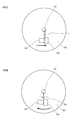
- a problem that the invention is to solve will be described using schematic views of Figs. 6 to 8 .
- a reduction gear 102 is also inclined and a protrusion 103 provided in the reduction gear 102 is also inclined. Consequently, the protrusion 103 is displaced by a displacement x in an arrow b direction so as to overlap with a stopper 201.
- the protrusion 103 tries to push the stopper 201 from the left to the right of Fig. 7 by the displacement x in the arrow b direction. However, since the stopper 201 is provided in the case and is immovable, the protrusion 103 rotates about the needle pointer shaft 101 from the right to the left of Fig. 8 by an angle ⁇ 2 in an arrow c direction as a reaction.
- the reduction gear 102 engages with the rotor.
- the rotation of the rotor is decelerated to be transmitted to the reduction gear 102, whereas the rotation of the reduction gear 102 is accelerated to be transmitted to the rotor. Accordingly, the rotation of the reduction gear 102 by the angle ⁇ 2 is accelerated to be transmitted to the rotor.
- An angle of the rotor which rotates together with the rotation of the reduction gear 102 upsets the state in which the rotor is stably retained by the attraction to the stator, and the protrusion 103 is separated from the stopper 201 at a position coming into contact with the stopper 201.
- the state in which the rotor is stably retained by the attraction to the stator for example, originally, the state in which the needle pointer indicates a "0" scale (not shown in the drawing) by the protrusion 103 coming into contact with the stopper 201 enters a failure state by receiving a vibration, an impact, or the like, and thus the protrusion 103 is separated from the stopper 201 and the needle pointer indicates a position different from the "0" scale (not shown in the drawing). Therefore, there was a problem that so-called a step-out state is reached.
- the present invention has been made in view of the above-mentioned problem, and an object thereof is to provide an instrument driving device with which it is possible to suppress a step-out caused by a vibration, an impact, or the like.
- An instrument driving device of the present invention includes a rotating magnet, a driving gear having the same axis as the magnet, an output gear driven by the magnet, a needle pointer shaft having a needle pointer mounted thereon and rotatably supports the output gear, a transmission gear that transmits rotation of the driving gear to the output gear, and a case that accommodates the magnet, the driving gear, the output gear, the transmission gear, and a portion of the needle pointer shaft, wherein the case is provided with a stopper and a bearing portion that rotatably supports the needle pointer shaft, the output gear is provided with a protrusion that comes into contact with the stopper, the bearing portion is provided with a contact point with which the needle pointer shaft comes into contact, and an end at the protrusion side of the stopper is provided at the same position as the contact point in an axial direction of the needle pointer shaft.
- a contact portion having the contact point may have a sectional circular shape in an axial direction of the bearing portion.
- a contact portion having the contact point may have a spherical surface shape.
- an end of the needle pointer shaft may have a planar surface in a direction perpendicular to the axial direction of the needle pointer shaft.
- an instrument driving device with which it is possible to suppress a step-out caused by a vibration, an impact, or the like.
- An instrument driving device 1 of the present embodiment is a stepping motor which is a kind of electric motor, and is used for an instrument device M including a needle pointer 14 and rotates the needle pointer 14.
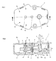
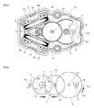
- the stepping motor 1 of the present embodiment includes a magnet 2, a driving gear 3 which has the same axis as the magnet 2, a transmission gear 4 which has a first gear 4a engaging with the driving gear 3 and a second gear 4b provided on the same axis as the first gear 4a, an output gear 5 which engages with the second gear 4b of the transmission gear 4, two coils 9 which generate a rotating magnetic field to apply a rotational force to the magnet 2, a first rotating shaft 10 which is a rotation center of the magnet 2, a second rotating shaft 11 which is a rotation center of the transmission gear 4, a needle pointer shaft 6 which is a rotation center of the output gear 5, a retention magnet 18, and a case 12 which accommodates the magnet 2, the driving gear 3, the transmission gear 4, the output gear 5, the needle pointer shaft 6, the coils 9, the first rotating shaft 10, the second rotating shaft 11, and the retention magnet 18.
- the magnet 2 is made of a synthetic resin including a magnetic material which is referred to as a so-called plastic magnet.
- the magnet 2 has a doughnut shape which has a through hole at a circular center thereof.
- the driving gear 3 and the first rotating shaft 10 pass through the through hole. It is sufficient if the magnet 2 includes one or more each of an N-pole and an S-pole.
- the magnet 2 includes four magnetic poles in total of two N-poles and two S-poles, and the magnetic poles are provided so as to be radially uniform about a rotation axis of the magnet 2. Accordingly, the magnetic poles are multipolar-magnetized on an outer peripheral surface of the magnet 2 along a rotational direction thereof using the first rotating shaft 10 as a central shaft.
- the driving gear 3 is made of a synthetic resin without magnetism.
- the driving gear 3 is provided on the same axis as the magnet 2 and rotates together with the rotation of the magnet 2.
- the first rotating shaft 10 passes through the driving gear 3.
- the transmission gear 4 is made of a synthetic resin without magnetism, and is integrally provided with the first gear 4a and the second gear 4b.
- the first gear 4a engages with the driving gear 3.
- the second gear 4b engages with the output gear 5.
- the transmission gear 4 is provided with the second rotating shaft 11 which is a rotation center.
- the output gear 5 is also made of a synthetic resin without magnetism, and engages with the second gear 4b of the transmission gear 4.
- the output gear 5 is provided with the needle pointer shaft 6 which is a rotation center.
- a protrusion 15 is integrally provided on a lower side surface of the output gear 5.
- the protrusion 15 includes a contact portion 15a which comes into contact with a stopper 16 provided in the case 12 to be described later.
- the protrusion 15 stops the rotation of the needle pointer shaft 6 at a predetermined position and determines a rotation range of the needle pointer shaft 6, by coming into contact with the stopper 16.
- a speed reduction mechanism including the driving gear 3, the transmission gear 4, and the output gear 5 is provided, and decelerates the rotation of the magnet 2 to transmit the decelerated rotation of the magnet 2 to the output gear 5.
- the needle pointer shaft 6 is axially supported to be rotatable by the case 12, and a portion of the needle pointer shaft 6 protrudes to the outside. Furthermore, an end 6a of the needle pointer shaft 6 has a planar surface in a direction perpendicular to the axial direction of the needle pointer shaft 6.
- Each of the coils 9 is to wind a metal wire such as copper having conductivity around a bobbin 9a made of a synthetic resin.
- the coil 9 is connected to a control unit (not shown) through terminals 9b provided at the bobbin 9a.
- the bobbin 9a is a cylinder formed with a through hole having a sectional rectangular shape.
- the coil 9 is arranged on a periphery of the magnet 2, and a portion of a disk surface of the magnet 2 faces an inner peripheral surface of the through hole in the state in which a portion of the magnet 2 is penetrated into the through hole of the bobbin 9a.
- the case 12 is made of a synthetic resin without magnetism, and divided into upper and lower portions.
- the case 12 divided into the upper and lower portions is fixed by hooking a lock claw 12a provided at each of the upper and lower portions of the case 12.
- the case 12 rotatably supports the first rotating shaft 10, the second rotating shaft 11, and the needle pointer shaft 6. Particularly, in order to rotatably support the needle pointer shaft 6, the case 12 includes an upper bearing portion 12b indicative of the middle of the needle pointer shaft 6 and a lower bearing portion 12c to rotatably support the end 6a of the needle pointer shaft 6.
- the upper bearing portion 12b is a through hole, and the lower bearing portion 12c is a recessed concave portion.
- the bottom of the lower bearing portion 12c comes into contact with the needle pointer shaft 6, and includes a contact portion 12e having a contact point 12d which is a support point where the needle pointer shaft 6 is inclined.
- the contact portion 12e having the contact point 12d has a sectional circular shape in the axial direction of the lower bearing portion 12c. Furthermore, in the present embodiment, the contact portion 12e having the contact point 12d has a spherical surface shape.
- the case 12 is integrally provided with the stopper 16 which comes into contact with the protrusion 15 provided on the output gear 5.
- the stopper 16 is a protruding three-dimensional object, and includes a contact portion 16a which comes into contact with the protrusion 15.
- the contact portion 15a of the protrusion 15 comes into contact with the contact portion 16b of the stopper 16.
- An end 16b at the protrusion 15 side of the stopper 16, that is, a height of the stopper 16 is the same position as the contact point 12d in the axial direction of the needle pointer shaft 6, as indicated by the dotted line in Fig. 2 .
- the retention magnet 18 is made of a synthetic resin including a magnetic material which is referred to as so-called a plastic magnet, and has a columnar shape.
- the retention magnet 18 is provided in the vicinity of an outer periphery of the magnet 2.
- the retention magnet 18 retains a stationary state using a magnetic force when the magnet 2 is static.
- the instrument driving device 1 of the present embodiment includes the retention magnet 18, as a substitute for the stator which, when the magnet 2 is static, suppresses the rotation of the magnet 2 to carry out a retention function and is made of a magnetic material, similarly to the conventional instrument driving device.
- the retention magnet 18 includes one each of an N-pole and an S-pole.
- the S-pole side is arranged to be directed toward the magnet 2 side.
- a relation between the magnet 2 and the retention magnet 18 corresponds to the state in which the S-pole S1 of the magnet 2 is repelled against the S-pole of the retention magnet 18 and the N-pole N2 of the magnet 2 is attracted to the S-pole of the retention magnet 18.
- a force rotating in an arrow d direction is applied to the magnet 2.
- the magnet 2 is stably retained in the stationary state by the magnetic force of the retention magnet 18.
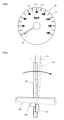
- Fig. 5 shows that the stepping motor 1 is used for the instrument device M.
- the instrument device M of the present embodiment indicates a vehicle speed using the needle pointer 14.
- the needle pointer 14 is mounted on the needle pointer shaft 6.
- the needle pointer 14 is provided at the back thereof with a display board 17 which includes an index portion 17a such as a scale or a character indicated by the needle pointer 14.
- the needle pointer 14 is stopped at a predetermined position, or a position indicative of "0" of the vehicle speed in the present embodiment, by the protrusion 15 and the stopper 16 provided in the stepping motor 1.
- the present invention is available for an instrument driving device including a reduction mechanism.
Landscapes
- Physics & Mathematics (AREA)
- General Physics & Mathematics (AREA)
- Engineering & Computer Science (AREA)
- Power Engineering (AREA)
- Connection Of Motors, Electrical Generators, Mechanical Devices, And The Like (AREA)
- Instrument Panels (AREA)
- Details Of Measuring Devices (AREA)
Applications Claiming Priority (2)
| Application Number | Priority Date | Filing Date | Title |
|---|---|---|---|
| JP2010206254A JP5397702B2 (ja) | 2010-09-15 | 2010-09-15 | 計器用駆動装置 |
| PCT/JP2011/068733 WO2012035926A1 (ja) | 2010-09-15 | 2011-08-19 | 計器用駆動装置 |
Publications (2)
| Publication Number | Publication Date |
|---|---|
| EP2618111A1 true EP2618111A1 (de) | 2013-07-24 |
| EP2618111A4 EP2618111A4 (de) | 2017-06-14 |
Family
ID=45831400
Family Applications (1)
| Application Number | Title | Priority Date | Filing Date |
|---|---|---|---|
| EP11824934.1A Withdrawn EP2618111A4 (de) | 2010-09-15 | 2011-08-19 | Instrumentenantriebsvorrichtung |
Country Status (6)
| Country | Link |
|---|---|
| US (1) | US9074913B2 (de) |
| EP (1) | EP2618111A4 (de) |
| JP (1) | JP5397702B2 (de) |
| KR (1) | KR101820552B1 (de) |
| CN (1) | CN103109162B (de) |
| WO (1) | WO2012035926A1 (de) |
Families Citing this family (7)
| Publication number | Priority date | Publication date | Assignee | Title |
|---|---|---|---|---|
| JP5322033B2 (ja) * | 2009-07-21 | 2013-10-23 | 日本精機株式会社 | 計器用駆動装置 |
| US9970792B2 (en) * | 2014-08-11 | 2018-05-15 | Continental Automotive Systems, Inc. | Stepper motor assembly having opposite shafts |
| JP6431751B2 (ja) * | 2014-11-21 | 2018-11-28 | 日本電産サンキョー株式会社 | ギアードモータおよび指針式表示装置 |
| JP6460748B2 (ja) * | 2014-11-21 | 2019-01-30 | 日本電産サンキョー株式会社 | ギアードモータおよび指針式表示装置 |
| JP6460749B2 (ja) * | 2014-11-21 | 2019-01-30 | 日本電産サンキョー株式会社 | ギアードモータおよび指針式表示装置 |
| JP2017204927A (ja) * | 2016-05-11 | 2017-11-16 | 日本電産サンキョー株式会社 | ギアードモータおよび指針式表示装置 |
| JP6733593B2 (ja) | 2017-04-13 | 2020-08-05 | 株式会社デンソー | ステップモータ及び車両用指針計器 |
Family Cites Families (11)
| Publication number | Priority date | Publication date | Assignee | Title |
|---|---|---|---|---|
| JPS5724876A (en) * | 1980-07-21 | 1982-02-09 | Matsushita Electric Works Ltd | Gear device for watch |
| JPS6182284A (ja) | 1983-12-28 | 1986-04-25 | Ricoh Co Ltd | ストロ−ク抽出方式 |
| JPH032861Y2 (de) * | 1984-11-02 | 1991-01-25 | ||
| JPH0473878U (de) * | 1990-11-09 | 1992-06-29 | ||
| JP2848503B2 (ja) * | 1992-07-14 | 1999-01-20 | 矢崎総業株式会社 | クロスコイル形指示計器 |
| WO2001009624A1 (fr) * | 1999-07-30 | 2001-02-08 | Nippon Seiki Co., Ltd | Metre a spirale |
| JP3754595B2 (ja) * | 2000-05-10 | 2006-03-15 | 矢崎総業株式会社 | 指示計器及び該指示計器の組み立て方法 |
| JP2003214911A (ja) * | 2002-01-17 | 2003-07-30 | Denso Corp | 計 器 |
| JP5158345B2 (ja) * | 2007-12-28 | 2013-03-06 | 日本精機株式会社 | ステッピングモータを用いた計器装置 |
| JP5233319B2 (ja) * | 2008-02-27 | 2013-07-10 | 日本精機株式会社 | 計器用ステッピングモータ |
| CN201478933U (zh) * | 2009-09-14 | 2010-05-19 | 宁波瑞可电机有限公司 | 一种汽车仪用永磁微型电动机 |
-
2010
- 2010-09-15 JP JP2010206254A patent/JP5397702B2/ja not_active Expired - Fee Related
-
2011
- 2011-08-19 KR KR1020137007055A patent/KR101820552B1/ko not_active Expired - Fee Related
- 2011-08-19 CN CN201180044278.3A patent/CN103109162B/zh not_active Expired - Fee Related
- 2011-08-19 US US13/821,023 patent/US9074913B2/en not_active Expired - Fee Related
- 2011-08-19 WO PCT/JP2011/068733 patent/WO2012035926A1/ja not_active Ceased
- 2011-08-19 EP EP11824934.1A patent/EP2618111A4/de not_active Withdrawn
Non-Patent Citations (1)
| Title |
|---|
| See references of WO2012035926A1 * |
Also Published As
| Publication number | Publication date |
|---|---|
| CN103109162B (zh) | 2015-07-01 |
| JP2012063185A (ja) | 2012-03-29 |
| CN103109162A (zh) | 2013-05-15 |
| US9074913B2 (en) | 2015-07-07 |
| KR101820552B1 (ko) | 2018-01-19 |
| KR20140009124A (ko) | 2014-01-22 |
| JP5397702B2 (ja) | 2014-01-22 |
| EP2618111A4 (de) | 2017-06-14 |
| US20130160582A1 (en) | 2013-06-27 |
| WO2012035926A1 (ja) | 2012-03-22 |
Similar Documents
| Publication | Publication Date | Title |
|---|---|---|
| EP2618111A1 (de) | Instrumentenantriebsvorrichtung | |
| JP6429115B2 (ja) | モータ | |
| JP6016273B2 (ja) | ロータリーアクチュエータ及びそれを用いた操作感触付与型入力装置 | |
| US11408485B2 (en) | Electric actuator | |
| EP3220519B1 (de) | Motor mit entschleunigungsmechanismus | |
| EP3035102B1 (de) | Drehkörperantriebsvorrichtung | |
| EP2618463A2 (de) | Motor | |
| CN109923769B (zh) | 旋转位置检测装置 | |
| CN112583187A (zh) | 马达单元 | |
| EP1911988B1 (de) | Antriebsvorrichtung | |
| US11757318B2 (en) | Rotor and motor having same | |
| CN113765289B (zh) | 马达、马达单元 | |
| JP2020162399A (ja) | ブラシレスモータ | |
| CN211426764U (zh) | 环磁铁以及磁传感器 | |
| WO2015125792A1 (ja) | 電気モータの回転量検出装置 | |
| US12500472B2 (en) | Motor device | |
| CN103312063B (zh) | 电动机的转子、电动机及洗衣机 | |
| EP4280436A1 (de) | Antriebsvorrichtung und ventil | |
| JP2008151228A (ja) | 電磁クラッチ装置およびその製造方法 | |
| CN121036419A (zh) | 电动马达 | |
| EP2422936B1 (de) | Magnetisch gesteuerter Aktuator mit Selbstverriegelungsfunktion für die Gelenkverbindungen eines Manipulationsarms | |
| CN210350958U (zh) | 环磁铁以及磁传感器 | |
| US20120187781A1 (en) | Motor | |
| JP2024068424A (ja) | モータ | |
| JP2024031375A (ja) | 電動アクチュエータ |
Legal Events
| Date | Code | Title | Description |
|---|---|---|---|
| PUAI | Public reference made under article 153(3) epc to a published international application that has entered the european phase |
Free format text: ORIGINAL CODE: 0009012 |
|
| 17P | Request for examination filed |
Effective date: 20130313 |
|
| AK | Designated contracting states |
Kind code of ref document: A1 Designated state(s): AL AT BE BG CH CY CZ DE DK EE ES FI FR GB GR HR HU IE IS IT LI LT LU LV MC MK MT NL NO PL PT RO RS SE SI SK SM TR |
|
| DAX | Request for extension of the european patent (deleted) | ||
| RIN1 | Information on inventor provided before grant (corrected) |
Inventor name: WATANABE, MASAHIRO |
|
| RA4 | Supplementary search report drawn up and despatched (corrected) |
Effective date: 20170511 |
|
| RIC1 | Information provided on ipc code assigned before grant |
Ipc: G01D 13/22 20060101AFI20170505BHEP |
|
| STAA | Information on the status of an ep patent application or granted ep patent |
Free format text: STATUS: THE APPLICATION HAS BEEN WITHDRAWN |
|
| 18W | Application withdrawn |
Effective date: 20170706 |