EP2618263A2 - Cache-Vorrichtung, Kommunikationsvorrichtung und Computerprogrammprodukt - Google Patents
Cache-Vorrichtung, Kommunikationsvorrichtung und Computerprogrammprodukt Download PDFInfo
- Publication number
- EP2618263A2 EP2618263A2 EP20130151540 EP13151540A EP2618263A2 EP 2618263 A2 EP2618263 A2 EP 2618263A2 EP 20130151540 EP20130151540 EP 20130151540 EP 13151540 A EP13151540 A EP 13151540A EP 2618263 A2 EP2618263 A2 EP 2618263A2
- Authority
- EP
- European Patent Office
- Prior art keywords
- cache
- unit
- cache data
- referencing
- time
- Prior art date
- Legal status (The legal status is an assumption and is not a legal conclusion. Google has not performed a legal analysis and makes no representation as to the accuracy of the status listed.)
- Ceased
Links
Images


Classifications
-
- G—PHYSICS
- G06—COMPUTING OR CALCULATING; COUNTING
- G06F—ELECTRIC DIGITAL DATA PROCESSING
- G06F12/00—Accessing, addressing or allocating within memory systems or architectures
- G06F12/02—Addressing or allocation; Relocation
- G06F12/08—Addressing or allocation; Relocation in hierarchically structured memory systems, e.g. virtual memory systems
- G06F12/0802—Addressing of a memory level in which the access to the desired data or data block requires associative addressing means, e.g. caches
- G06F12/0875—Addressing of a memory level in which the access to the desired data or data block requires associative addressing means, e.g. caches with dedicated cache, e.g. instruction or stack
-
- G—PHYSICS
- G06—COMPUTING OR CALCULATING; COUNTING
- G06F—ELECTRIC DIGITAL DATA PROCESSING
- G06F12/00—Accessing, addressing or allocating within memory systems or architectures
- G06F12/02—Addressing or allocation; Relocation
- G06F12/08—Addressing or allocation; Relocation in hierarchically structured memory systems, e.g. virtual memory systems
- G06F12/0802—Addressing of a memory level in which the access to the desired data or data block requires associative addressing means, e.g. caches
- G06F12/0893—Caches characterised by their organisation or structure
- G06F12/0897—Caches characterised by their organisation or structure with two or more cache hierarchy levels
-
- G—PHYSICS
- G06—COMPUTING OR CALCULATING; COUNTING
- G06F—ELECTRIC DIGITAL DATA PROCESSING
- G06F12/00—Accessing, addressing or allocating within memory systems or architectures
- G06F12/02—Addressing or allocation; Relocation
- G06F12/08—Addressing or allocation; Relocation in hierarchically structured memory systems, e.g. virtual memory systems
- G06F12/12—Replacement control
- G06F12/121—Replacement control using replacement algorithms
Definitions
- the present invention relates to a cache device, a communication apparatus, and a computer program product.
- DCSs distributed control systems
- on-site equipment known as field devices
- device management apparatuses that manage and control the field devices via a communication bus
- cache devices are often used to alleviate delay in data transfer to the minimum possible, and to improve transmission efficiency.
- a cache device used in a distributed control system holds device property information obtained from field devices and parameter property information obtained from a DD (device description) file created using a DDS (data description specification) as cache data in a memory such as a RAM (random-access memory) or the like.
- the above-noted device property information is a tag indicating the ID (identifier) or name of a field device, the internal field device calculation time period, and information indicating other characteristics of the field device.
- the above-noted parameter property information is parameters used in the field device (for example, parameters into which measurement results are stored, or parameters for calculations), such as data length, sign, moniker, and information indicating other characteristics.
- the above-noted cache device obtains and holds as cache data the device property information and parameter property information required for the execution of processing in response to the request from the field device and the DD file, and executes processing in response to the request. Then, if the same request is received again, by executing the processing in response to the request using device property information and parameter property information that are held as cache data, the time required for obtaining the device property information from the field device and the time required for analyzing the DD file to obtain the parameter property information are eliminated.
- a host device for example, a device management apparatus
- Japanese Unexamined Patent Application, First Publication No. 2003-333121 discloses a field device communication apparatus provided between a host device and a controller that controls a field device, which fully asynchronously communicates with a GUI means of the host device and which communicates with the field device via the controller. Additionally, Japanese Unexamined Patent Application, First Publication No. 2006-91961 discloses a communication interface that has a request cache in which a request from a host application is registered and a response cache in which a response from a field device is stored.
- a cache device may include: a first storage unit configured to store first cache data; a second storage unit configured to store a cache file that stores copy of the first cache data as second cache data; a reading unit configured to select and read out one of the first cache data, which has been stored in the first storage unit, and the second cache data, which has been stored in the cache file stored in the second storage unit, in response to a reference request from outside; and an instructing unit configured to determine probability of expecting future referencing request based on the frequency of past referencing requests, the instructing unit being configured to instruct that either the first cache data or the second cache data is to be selected and read out based on the probability.
- the instructing unit may be configured to calculate an average value of the past referencing requests per unit time, and to determine the probability of expecting future referencing request based on an exponential distribution taking the average value as a parameter.
- the instructing unit may be configured to calculate each of the probabilities of expecting future referencing request up until a plurality of points in time and to instruct the reading unit to select and read one of the first cache data and the second cache data based on an increasing/decreasing trend of the probabilities that have been calculated.
- the reading unit may be configured to delete the corresponding first cache data, which has been stored in the first storage unit, if the reading unit, based on an instruction from the instructing unit, switches from reading the first cache data stored in the first storage unit to reading the second cache data in the cache files stored in the second storage unit.
- the cache device may further include: a referencing counter configured to count the number of the referencing events during a unit of time; and an event counter configured to count the number of the referencing events in parameter unit time that is established as a time that is shorter than the unit of time.
- a communication apparatus that communicates with a field device may include: a DD file holding unit configured to hold parameter property information indicating characteristics of a parameter used in the field device; and the cache device comprising: a first storage unit configured to store device property information, which is obtained from the field device and indicates characteristics of the field device, and the parameter property information, which is obtained from the DD file holding unit, as first cache data; a second storage unit configured to store a cache file that stores copy of the first cache data as second cache data; a reading unit configured to select and read out one of the first cache data, which has been stored in the first storage unit, and the second cache data, which has been stored in the cache file stored in the second storage unit, in response to a reference request from outside; and an instructing unit configured to determine probability of expecting future referencing request based on the frequency of past referencing requests, the instructing unit being configured to instruct that either the first cache data or the second cache data is to be selected and read out based on the probability.
- the instructing unit may be configured to calculate an average value of the past referencing requests per unit time, and to determine the probability of expecting future referencing request based on an exponential distribution taking the average value as a parameter.
- the instructing unit may be configured to calculate each of the probabilities of expecting future referencing request up until a plurality of points in time and to instruct the reading unit to select and read one of the first cache data and the second cache data based on an increasing/decreasing trend of the probabilities that have been calculated.
- the reading unit is configured to delete the corresponding first cache data, which has been stored in the first storage unit, if the reading unit, based on an instruction from the instructing unit, switches from reading the first cache data stored in the first storage unit to reading the second cache data in the cache files stored in the second storage unit.
- the cache device may further include: a referencing counter configured to count the number of the referencing events during a unit of time; and an event counter configured to count the number of the referencing events in parameter unit time that is established as a time that is shorter than the unit of time.
- the communication apparatus may further include: a queue processor including a FIFO memory.
- the instructing unit may be configured to set the parameter unit time as a time during which a read request or a write request, which is sent once from the terminal device for a purpose of referencing the parameters of the field device, is held in the FIFO memory.
- the communication apparatus may further include: a communication processor. If there is a request for reading or writing of the parameters of the field device from outside, then the communication processor may obtain each of the device property information and the parameter property information, which are required for execution of processing in response to the request, from the field device and the DD file holding unit, respectively, and perform processing for writing the device property information and the parameter property information as cache data into the cache device. If the same request occurs again, then the communication processor may perform processing for reading of the device property information and the parameter property information that are held as the cache data in the cache device.
- a communication processor may obtain each of the device property information and the parameter property information, which are required for execution of processing in response to the request, from the field device and the DD file holding unit, respectively, and perform processing for writing the device property information and the parameter property information as cache data into the cache device. If the same request occurs again, then the communication processor may perform processing for reading of the device property information and the parameter property information that are held as the cache data in the cache device.
- a computer program product embodied on a non-transitory computer readable medium may include: instructions to store first cache data in first storage means; instructions to store a cache file that stores copy of the first cache data as second cache data in second storage means; instructions to select and read out one of the first cache data, which has been stored in the first storage means, and the second cache data, which has been stored in the cache file stored in the second storage means, in response to a reference request from outside; and instructions to determine probability of expecting future referencing request based on the frequency of past referencing requests and to instruct that either the first cache data or the second cache data is to be selected and read out based on the probability.
- the computer program product may further include: instructions to calculate an average value of the past referencing requests per unit time, and to determine the probability of expecting future referencing request based on an exponential distribution taking the average value as a parameter.
- the computer program product may further include: instructions to calculate each of the probabilities of expecting future referencing request up until a plurality of points in time and to instruct the reading unit to select and read one of the first cache data and the second cache data based on an increasing/decreasing trend of the probabilities that have been calculated.
- the computer program product may further include: instructions to delete the corresponding first cache data, which has been stored in the first storage unit, if the reading unit, based on an instruction from the instructing unit, switches from reading the first cache data stored in the first storage unit to reading the second cache data in the cache files stored in the second storage unit.
- the computer program product may further include: instructions to count the number of the referencing events during a unit of time; and instructions to count the number of the referencing events in parameter unit time that is established as a time that is shorter than the unit of time.
- FIG. 1 is a block diagram showing the main part of the constitution of a communication apparatus in accordance with the first preferred embodiment of the present invention.
- a field device communication apparatus 1 is connected to a network N1 and a field bus B1.
- the field device communication apparatus 1 can communicate with a terminal device 2 connected to the network N1 and field devices 31,32 and 33 connected to the field bus B1.
- field devices 31, 32 and 33 will be connected directly to the field bus B1, field devices 31, 32 and 33 may alternatively be connected to the field bus B1 via a controller that controls the field devices. Additionally, although in this case one terminal device 2 is directly connected to the network N1 to which the field device communication apparatus 1 is connected, the constitution of the network that connects the field device communication apparatus 1 and the terminal device 2 is arbitrary, as is the number of terminal devices 2 connected to the network N1.
- the field device communication apparatus 1 has a fully asynchronous interface unit 11, a queue processor 12, a communication processor 13, a field communication interface unit 14, a DD file holding unit 15, and a cache module 16.
- the DD file holding unit 15 stores a DD (device description) file created by using a DDS (data description specifcation).
- the DD file stores parameter property information indicating characteristics of a parameter used in the field devices 31, 32 and 33.
- the cache module 16 may hereinafter be referred to as a cache device.
- the fully asynchronous interface unit 11 is connected to the network N1, and communicates asynchronously with the terminal device 2 via the network N1 therebetween.
- the queue processor 12 has a FIFO (first-in, first-out) memory 17.
- the queue processor 12 performs input/output processing of data with the fully asynchronous interface unit 11, so that asynchronous communication with the fully asynchronous interface unit 11 is performed smoothly.
- the communication processor 13 controls communication performed with the terminal device 2 via the network N1, and communication performed with the field devices 31, 32 and 33 via the field bus B1.
- the communication processor 13 also writes data to be stored as cache data into the cache module 16, and performs processing of to retrieve cache data held in the cache module 16 as necessary.
- the communication processor 13 obtains each of the device property information and parameter property information, which are required for execution of processing in response to the request, from the field devices 31, 32 and 33 and the DD file holding unit 15, respectively, and performs processing for writing thereof as cache data into the cache module 16. If the same request occurs again, the communication processor performs processing for the reading of device property information and parameter property information that are held as cache data in the cache module 16.
- the above-noted device property information is a tag indicating the ID (identifier) or name of a field device, the internal field device calculation time period, and information indicating other characteristics of the field device.
- the above-noted parameter property information is one that indicates data length, sign, moniker and other characteristics of parameters used in the field device (for example, parameters into which measurement results are stored, or parameters for calculations).
- the field communication interface unit 14 is connected to the field bus B1, and communicates with the field devices 31, 32 and 33 via the field bus B1.
- the field communication interface unit 14 can be one that performs communication conforming to a plurality of general-purpose industrial process communication protocols, such as HART (Highway Addressable Remote Transducer; registered trademark), Foundation Fieldbus (registered trademark), PROFIBUS (registered trademark), or BRAIN communication protocols.
- the DD field holding unit 15 stores a DD (device description) file that is created using a DDS (data description specification) and in which the above-described parameter property information is coded.
- the cache module 16 is a module that holds the above-described device property information and parameter property information as cache data.
- FIG. 2 is a block diagram showing the main parts of the constitution of the cache module 16 in accordance with the first preferred embodiment of the present invention.
- the cache module 16 has an interface unit 21, a RAM 22, a disk apparatus 23, a cache data selector unit 24, a cache monitoring unit 25, a referencing counter 26, and an event counter 27.
- the RAM 22 may hereinafter be referred to as a first storage unit or first storage means.
- the disk apparatus 23 may hereinafter be referred to as a second storage unit or second storage means.
- the cache data selector unit 24 may hereinafter be referred to as a reading unit or reading means.
- the cache monitoring unit 25 may hereinafter be referred to as an instructing unit or instructing means.
- the interface unit 21 performs input/output processing of device property information and parameter property information as cache data with the communication processor 13 provided in the field device communication apparatus 1.
- the RAM 22 is a volatile memory such as, for example, a DRAM (dynamic random-access memory) that stores device property information and parameter property information from the communication processor 13 as the cache data D1 to Dn, under the control of the cache data selector unit 24.
- DRAM dynamic random-access memory
- the disk apparatus 23 is, for example, a hard disk apparatus.
- the disk apparatus 23 stores data that is copy of the cache data D1 to Dn in the corresponding cache files F1 to Fn, under the control of the cache data selector unit 24. Specifically, copy of the cache data D1 is stored in the cache file F1 stored in the disk apparatus 23, copy of the cache data D2 is stored in the cache file F2 stored in the disk apparatus 23, and copy of the cache data Dn is stored in the cache file Fn stored in the disk apparatus 23.
- the cache data selector unit 24 writes data into the RAM 22 and the disk apparatus 23, and also reads data from the RAM 22 and the disk apparatus 23, based on instructions from the cache monitoring unit 25. Specifically, when device property information and parameter property information are input via the interface unit 21 from the communication processor 13, the cache data selector unit 24 causes the RAM 22 to store the information as the cache data D1 to Dn and also causes the cache files F1 to Fn stored in the disk apparatus 23 to store the copy of the corresponding cache data D1 to Dn. Specifically, copy of the cache data D1 is stored in the cache file F1 stored in the disk apparatus 23, copy of the cache data D2 is stored in the cache file F2 stored in the disk apparatus 23, and copy of the cache data Dn is stored in the cache file Fn stored in the disk apparatus 23.
- the cache data selector unit 24 makes notification to that effect, which is hereinafter referred to as a referencing event notification, to the cache monitoring unit 25. Also, when a referencing event is input from the communication processor 13, the cache data selector unit 24, based on an instruction from the cache monitoring unit 25, selects and reads one of the cache data D1 to Dn stored in the RAM 22 and the cache data in the cache files F1 to Fn stored in the disk unit 23.
- the cache monitoring unit 25 monitors the frequency of referencing the cache data D1 to Dn stored in RAM 22, and instructs, using this monitor results, selection and reading of one of the cache data D1 to Dn stored in the RAM 22 and the cache data in the cache files F1 to Fn stored in the disk apparatus 23.
- cache monitoring processes P1 to Pn corresponding to each of the cache data D1 to Dn stored in the RAM 22 are executed, thereby individually monitoring the cache data D1 to Dn.
- the cache monitoring unit 25 calculates the average number of past referencing event with respect to each of the cache data D1 to Dn stored in the RAM 22 per unit time, and determines, based on an exponential distribution taking the average number of times for each as a parameter, the probability of future referencing events for each of the cache data D1 to Dn.
- the probability P(t) of a referencing event expected at a time t in the future from the current point in time is given by the following Equation (1).
- P t 1 - exp - ⁇ ⁇ t
- the cache monitoring unit 25 determines the each of the probabilities of expecting a future referencing event up until a plurality of points in time and, depending upon the increasing/decreasing trend of the determined probabilities, and instructs the selection and reading of one of the cache data D1 to Dn stored in the RAM 22 and the cache data in the cache files F1 to Fn stored in the disk apparatus 23. For example, if the determined probabilities are on an increasing trend, an instruction is issued so as to select and read the cache data D1 to Dn stored in the RAM 22, and if the determined probabilities are on a decreasing trend, an instruction is issued so as to select and read the cache data in the cache files F1 to Fn stored in the disk apparatus 23.
- the read request When a parameter read request with respect to the field devices 31, 32 and 33 is output from the field device 2, the read request is transmitted via the network N1 to the field device communication apparatus 1, and is received at the fully asynchronous interface unit 11 of the field device communication apparatus 1.
- the read request received at the fully asynchronous interface unit 11 is input to the communication processor 13 via the queue processor 12.
- the communication processor 13 controls the field communication interface unit 14, communicates with the field devices 31, 32 and 33 to acquire the device property information, and also interprets the DD file stored in the DD file holding unit 15 to acquire the parameter property information.
- the communication processor 13 outputs the acquired device property information and parameter property information as cache data to the cache module 16, and makes a response to the terminal device 2 in response to the read request from the terminal device 2. This response is transmitted to the terminal device 2 via the queue processor 12 and the fully asynchronous interface unit 11.
- the cache data output from the communication processor 13 is input to the cache data selector unit 24 via the interface unit 21 of the cache module 16, and is stored as cache data D1 in the RAM 22, and a cache file F1 is created in the disk apparatus 23 so as to store copy of the cache data D1.
- information indicating that cache data D1 has been stored is output from the cache data selector 24 to the cache monitoring unit 25, and the cache monitoring process P1 is executed at the cache monitoring unit 25.
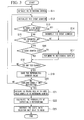
- FIG. 3 is a flowchart showing the operation of the cache monitoring unit 25 of the cache device 16 in accordance with the first preferred embodiment of the present invention.
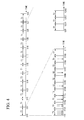
- FIG. 4 is a timing diagram for describing the operation performed at the cache monitoring unit 25 of the cache device 16 in accordance with the first preferred embodiment of the present invention.
- the cache monitoring unit 25 uses two counters, the referencing counter 26 and the event counter 27, for the purpose of calculating the average number of past referencing events per unit time with respect to the cache data D1 stored in the RAM 22.
- the referencing counter 26 counts the number of referencing events during the above-noted unit of time.
- the event counter 27 counts the number of referencing events in a time that is established as a time that is shorter than the above-noted unit of time and is hereinafter referred to as a parameter unit time.
- the above-noted unit of time is the time T1 as shown in FIG. 4 (for example the time from time t1 0 to time t11), this being set to, for example, 1 second.
- the above-noted parameter unit time is a time T2 as shown in FIG. 4 (for example, time from time t10 to time t101), this being set to, for example, 0.1 second.
- the cache monitoring unit 25 sets the above-noted parameter unit time T2, for example, as the time during which a read request or a write request, which is sent once from the terminal device 2 for the purpose of referencing a parameter of the field devices 31, 32 and 33, is held in a FIFO memory 17 provided in the queue processor 12 of the field device communication apparatus 1.
- the setting of this type of parameter unit time T2 and the use of an event counter that counts the number of referencing events occurring during the parameter unit time T2 are done so that, even if a plurality of referencing events occur within the parameter unit time T2, because the probability is calculated by Equation (1) based on an exponential distribution, the number of occurrences of a referencing event within the parameter unit time T2 is limited to one.
- the cache monitoring unit 25 When the processing of FIG. 3 starts, the cache monitoring unit 25 first initializes the referencing counter (step S11) and then initializes the event counter (step S12). When this initialization is completed, the cache monitoring unit 25 judges whether or not there is a reference event notification from the cache data selector unit 24 (step S13). If the judgment is that there is a referencing event notification (YES judgment result), the cache monitoring unit 25 increments the event counter (step S14) and once again judges whether there is a referencing event notification (step S13).
- the cache monitoring unit 25 judges whether or not the parameter unit time T2 has elapsed (step S15). For example, a judgment is made as to whether or not the time t101, which is a time later than the time t10 shown in FIG. 4 by the amount of the parameter unit time T2, has been reached. If the judgment is that the parameter unit time T2 has not elapsed (NO judgment result), a judgment is again made as to whether there is a referencing event notification (step S13).
- step S16 a judgment is made as to whether the value of the event counter is zero (step S16). If the judgment is that the event counter value is not zero (NO judgment result), the cache monitoring unit 25 increments the referencing counter (step S17) and judges whether the unit time T1 has elapsed (step S18). If, however, the judgment is that event counter value is zero (YES judgment result), the cache monitoring unit 25 does not increment the referencing counter and judges whether the unit time T1 has elapsed (step S18).
- step S18 a judgment is made, for example, of whether the time t11, which is a time later than the time t10 shown in FIG. 4 by the unit time T1, has been reached. If the judgment is that the unit time T1 has not elapsed (NO judgment result at step S18), the cache monitoring unit 25 initializes the event counter (step S12), and then performs referencing event monitoring in the following parameter unit time T2 (for example, in the time from time t101 to time t102) (steps S13 to S15).
- the cache monitoring unit 25 saves the referencing counter value (step S19) and judges whether the referencing event monitoring has been executed an established number of times in the unit time T1 (step S20). For example, a judgment is made as to whether referencing event has been monitored 10 times in the unit time T1, so that referencing event monitoring has been executed for all of the unit times T1, from the time t10 to the time t20 shown in FIG. 4 .
- the cache monitoring unit 25 initializes the referencing counter and the event counter (steps S11 and S12), and then monitors referencing event in the next unit time T1 (for example, the time from time t11 until time t12 (steps S13 to S18). If, however, the judgment is made that the referencing event monitoring has been executed the established number of times (YES judgment result at step S20), the cache monitoring unit 25 calculates the average value (average number of times ⁇ ) of the count value counted by the referencing counter (step S21). Specifically, the average value of the count values of the referencing counter held at step S19 is calculated.
- the cache monitoring unit 25 uses the above-described Equation (1) to calculate the probability of a referencing event occurring up until a future point in time (step S22). For example, if the current point in time is the time t20 shown in FIG. 4 , the cache monitoring unit 25 calculates the probability P(t201) of expecting a referencing event to occur from the time t20 until the time t201, which is the time that is the parameter unit time T2 thereafter, and the probability P(t202) of expecting a referencing event to occur from the time t201 until the time t202, which is the time that is the parameter unit T2 thereafter.
- the cache monitoring unit 25 instructs the cache data selector unit 24 of whether to select and read the cache data D1 stored in the RAM 22 or the cache data in the cache file F1 stored in the disk apparatus 23 (step S23). For example, in the above-noted example, because there is no expectation of a referencing event occurring in the time from time t20 until time t201, but there is an expectation of a referencing event occurring in the time from time t20 until time t202, the cache monitoring unit 25 instructs the reading of the cache data D1 stored in the RAM 22.
- the cache monitoring unit 25 instructs reading of the cache data in the cache file F1 stored in the disk apparatus 23. Also, if reading of the cache data D1 stored in the RAM 22 is switched to reading of the cache data in the cache file F1 stored in the disk apparatus 23, the cache data D1 stored in the RAM 22 is deleted by the cache data selector unit 24.
- the cache monitoring unit 25 instructs the reading of the cache data D1 stored in the RAM 22.
- the cache data selector unit 24 stores the cache data, which has been stored in the cache file F1 in the disk apparatus 23, into the RAM 22 as cache data D1.
- storing is done into the disk apparatus 23 as cache data in a cache file, the probability of expecting a future referencing request being determined in accordance with the past frequency of requests to reference cache data, and reading being done, based on that probability, of either the cache data in the RAM or the cache data in the cache file in the disk apparatus. For this reason, in addition to enabling effective use of memory, it is possible to increase the number of connectable field devices without expanding memory.
- the present invention is not restricted to the above-described preferred embodiment, and can be subject to various modifications, within the scope thereof.
- the description is for the case in the cache module 16 is incorporated as a cache device within the field device communication apparatus 1, it is possible to implement the cache module 16 as a standalone device.
- the cache module 16 it is desirable to store information used in the cache module 16 as the cache device (for example, information that sets forth the unit time T1, the parameter unit time T2 and the like) into a setting file, and to make the contents of the setting file changeable by editing.
- the functionality of the cache module 16 as the cache device may be implemented by hardware, or implemented in a software manner. That is, a program that implements the functionality of the cache module 16 can be installed into a computer, thereby enabling the software-like implementation of the functionality of the cache module 16.
- the program that implements the functionality of the cache module 16 may be stored on a recording medium such as a CD-ROM, and may also be downloaded from a network such as the Internet.
- the preferred embodiment of the present invention enables effective use of memory, and provides a cache device, a cache program, and a communication apparatus that enable an increase in the number of field devices that can be connected, without memory expansion.
- the probability of expecting a future referencing request is determined in accordance with the frequency of past referencing requests and, in accordance with that probability, either cache data stored in a first storage unit (RAM) or a cache data in the cache file stored in a second storage unit (disk apparatus) is selected and read out, thereby enabling effective use of memory.
- RAM first storage unit
- disk apparatus disk apparatus
- the term "configured” is used to describe a component, unit or part of a device includes hardware and/or software that is constructed and/or programmed to carry out the desired function.
- unit is used to describe a component, unit or part of a hardware and/or software that is constructed and/or programmed to carry out the desired function.
- Typical examples of the hardware may include, but are not limited to, a device and a circuit.
Landscapes
- Engineering & Computer Science (AREA)
- Theoretical Computer Science (AREA)
- Physics & Mathematics (AREA)
- General Engineering & Computer Science (AREA)
- General Physics & Mathematics (AREA)
- Memory System Of A Hierarchy Structure (AREA)
- Information Retrieval, Db Structures And Fs Structures Therefor (AREA)
Applications Claiming Priority (1)
| Application Number | Priority Date | Filing Date | Title |
|---|---|---|---|
| JP2012009137A JP5459325B2 (ja) | 2012-01-19 | 2012-01-19 | キャッシュ装置、キャッシュプログラム、及び通信装置 |
Publications (2)
| Publication Number | Publication Date |
|---|---|
| EP2618263A2 true EP2618263A2 (de) | 2013-07-24 |
| EP2618263A3 EP2618263A3 (de) | 2013-10-02 |
Family
ID=47603343
Family Applications (1)
| Application Number | Title | Priority Date | Filing Date |
|---|---|---|---|
| EP20130151540 Ceased EP2618263A3 (de) | 2012-01-19 | 2013-01-16 | Cache-Vorrichtung, Kommunikationsvorrichtung und Computerprogrammprodukt |
Country Status (4)
| Country | Link |
|---|---|
| US (1) | US9229871B2 (de) |
| EP (1) | EP2618263A3 (de) |
| JP (1) | JP5459325B2 (de) |
| CN (1) | CN103218310B (de) |
Cited By (1)
| Publication number | Priority date | Publication date | Assignee | Title |
|---|---|---|---|---|
| CN107193754A (zh) * | 2017-04-28 | 2017-09-22 | 网易(杭州)网络有限公司 | 进行数据存储用于搜索的方法及设备 |
Families Citing this family (22)
| Publication number | Priority date | Publication date | Assignee | Title |
|---|---|---|---|---|
| US9823626B2 (en) | 2014-10-06 | 2017-11-21 | Fisher-Rosemount Systems, Inc. | Regional big data in process control systems |
| US10223327B2 (en) * | 2013-03-14 | 2019-03-05 | Fisher-Rosemount Systems, Inc. | Collecting and delivering data to a big data machine in a process control system |
| US10649449B2 (en) | 2013-03-04 | 2020-05-12 | Fisher-Rosemount Systems, Inc. | Distributed industrial performance monitoring and analytics |
| US10386827B2 (en) | 2013-03-04 | 2019-08-20 | Fisher-Rosemount Systems, Inc. | Distributed industrial performance monitoring and analytics platform |
| US9665088B2 (en) | 2014-01-31 | 2017-05-30 | Fisher-Rosemount Systems, Inc. | Managing big data in process control systems |
| US10678225B2 (en) | 2013-03-04 | 2020-06-09 | Fisher-Rosemount Systems, Inc. | Data analytic services for distributed industrial performance monitoring |
| US10649424B2 (en) | 2013-03-04 | 2020-05-12 | Fisher-Rosemount Systems, Inc. | Distributed industrial performance monitoring and analytics |
| US9558220B2 (en) | 2013-03-04 | 2017-01-31 | Fisher-Rosemount Systems, Inc. | Big data in process control systems |
| US10866952B2 (en) | 2013-03-04 | 2020-12-15 | Fisher-Rosemount Systems, Inc. | Source-independent queries in distributed industrial system |
| US10282676B2 (en) | 2014-10-06 | 2019-05-07 | Fisher-Rosemount Systems, Inc. | Automatic signal processing-based learning in a process plant |
| US10909137B2 (en) | 2014-10-06 | 2021-02-02 | Fisher-Rosemount Systems, Inc. | Streaming data for analytics in process control systems |
| US9397836B2 (en) | 2014-08-11 | 2016-07-19 | Fisher-Rosemount Systems, Inc. | Securing devices to process control systems |
| US9740802B2 (en) | 2013-03-15 | 2017-08-22 | Fisher-Rosemount Systems, Inc. | Data modeling studio |
| US10120350B2 (en) * | 2013-03-11 | 2018-11-06 | Fisher-Rosemount Systems, Inc. | Background collection of diagnostic data from field instrumentation devices |
| AU2014244061B2 (en) * | 2013-03-14 | 2017-11-23 | Rosemount Inc. | Communications unit for an industrial process network |
| US10133243B2 (en) | 2013-03-15 | 2018-11-20 | Fisher-Rosemount Systems, Inc. | Method and apparatus for seamless state transfer between user interface devices in a mobile control room |
| DE102013107905A1 (de) * | 2013-07-24 | 2015-01-29 | Endress + Hauser Process Solutions Ag | Feldbuszugriffseinheit und Verfahren zum Betreiben derselben |
| US10168691B2 (en) | 2014-10-06 | 2019-01-01 | Fisher-Rosemount Systems, Inc. | Data pipeline for process control system analytics |
| CN106326142B (zh) * | 2015-06-17 | 2019-05-21 | 群联电子股份有限公司 | 缓冲存储器存取方法、存储器控制器与存储器存储装置 |
| US10503483B2 (en) | 2016-02-12 | 2019-12-10 | Fisher-Rosemount Systems, Inc. | Rule builder in a process control network |
| CN107065900B (zh) * | 2017-01-17 | 2020-04-28 | 清华大学 | 无人机飞行控制参数更新系统 |
| JP6859900B2 (ja) * | 2017-08-29 | 2021-04-14 | 横河電機株式会社 | モデム及び電子機器 |
Citations (3)
| Publication number | Priority date | Publication date | Assignee | Title |
|---|---|---|---|---|
| JP2003333121A (ja) | 2002-05-15 | 2003-11-21 | Yokogawa Electric Corp | フィールド機器通信装置 |
| JP2006091961A (ja) | 2004-09-21 | 2006-04-06 | Yokogawa Electric Corp | 通信インターフェイス |
| US7237061B1 (en) * | 2003-04-17 | 2007-06-26 | Realnetworks, Inc. | Systems and methods for the efficient reading of data in a server system |
Family Cites Families (10)
| Publication number | Priority date | Publication date | Assignee | Title |
|---|---|---|---|---|
| JPH04259048A (ja) * | 1991-02-14 | 1992-09-14 | Fujitsu Ltd | 統計情報による先読みデータ制御方式 |
| JPH05308366A (ja) * | 1992-05-06 | 1993-11-19 | Ricoh Co Ltd | Lanにおけるキャッシュシステム |
| US5606688A (en) * | 1994-08-31 | 1997-02-25 | International Business Machines Corporation | Method and apparatus for dynamic cache memory allocation via single-reference residency times |
| JP2976896B2 (ja) * | 1996-07-31 | 1999-11-10 | 日本電気株式会社 | リモートファイルのキャッシュ装置 |
| JP2005339198A (ja) * | 2004-05-27 | 2005-12-08 | Internatl Business Mach Corp <Ibm> | キャッシュヒット率推定装置、キャッシュヒット率推定方法、プログラム及び記録媒体 |
| US8144028B2 (en) * | 2005-01-24 | 2012-03-27 | Daniel Measurement And Control, Inc. | Method and system of obtaining data from field devices |
| JP2006253376A (ja) * | 2005-03-10 | 2006-09-21 | Oki Electric Ind Co Ltd | 半導体装置及びその製造方法 |
| US7676630B2 (en) * | 2006-10-05 | 2010-03-09 | Sun Microsystems, Inc. | Method and apparatus for using a determined file access pattern to perform caching in a file system |
| US8706968B2 (en) * | 2007-12-06 | 2014-04-22 | Fusion-Io, Inc. | Apparatus, system, and method for redundant write caching |
| JP5408257B2 (ja) * | 2009-07-22 | 2014-02-05 | 日本電気株式会社 | コンテンツ配信システム、コンテンツ配信方法、コンテンツ配信プログラム |
-
2012
- 2012-01-19 JP JP2012009137A patent/JP5459325B2/ja not_active Expired - Fee Related
-
2013
- 2013-01-16 US US13/742,790 patent/US9229871B2/en not_active Expired - Fee Related
- 2013-01-16 EP EP20130151540 patent/EP2618263A3/de not_active Ceased
- 2013-01-16 CN CN201310016129.7A patent/CN103218310B/zh not_active Expired - Fee Related
Patent Citations (3)
| Publication number | Priority date | Publication date | Assignee | Title |
|---|---|---|---|---|
| JP2003333121A (ja) | 2002-05-15 | 2003-11-21 | Yokogawa Electric Corp | フィールド機器通信装置 |
| US7237061B1 (en) * | 2003-04-17 | 2007-06-26 | Realnetworks, Inc. | Systems and methods for the efficient reading of data in a server system |
| JP2006091961A (ja) | 2004-09-21 | 2006-04-06 | Yokogawa Electric Corp | 通信インターフェイス |
Cited By (2)
| Publication number | Priority date | Publication date | Assignee | Title |
|---|---|---|---|---|
| CN107193754A (zh) * | 2017-04-28 | 2017-09-22 | 网易(杭州)网络有限公司 | 进行数据存储用于搜索的方法及设备 |
| CN107193754B (zh) * | 2017-04-28 | 2020-01-03 | 网易(杭州)网络有限公司 | 进行数据存储用于搜索的方法及设备 |
Also Published As
| Publication number | Publication date |
|---|---|
| US9229871B2 (en) | 2016-01-05 |
| CN103218310A (zh) | 2013-07-24 |
| EP2618263A3 (de) | 2013-10-02 |
| JP2013149087A (ja) | 2013-08-01 |
| US20130191597A1 (en) | 2013-07-25 |
| CN103218310B (zh) | 2015-12-23 |
| JP5459325B2 (ja) | 2014-04-02 |
Similar Documents
| Publication | Publication Date | Title |
|---|---|---|
| US9229871B2 (en) | Cache device, communication apparatus, and computer program product | |
| EP3382480B1 (de) | Steuergerät | |
| US9189485B2 (en) | Time-series data diagnosing/compressing method | |
| CN107766575B (zh) | 读写分离的数据库访问方法及装置 | |
| EP2829976A1 (de) | Verteiltes speichersystem, speichersteuerungsverfahren und programm | |
| US10908839B2 (en) | Storage device throttling amount of communicated data depending on suspension frequency of operation | |
| WO2000021252A1 (en) | Method and system for efficient packet data transport | |
| US20200068019A1 (en) | Equipment analysis support apparatus, equipment analysis support method, and equipment analysis system | |
| EP2000868A1 (de) | Verfahren zur Erfassung von Statusinformationen von E/A-Einheiten | |
| US12008072B2 (en) | Control system and control method | |
| EP3015931B1 (de) | Sps-system mit einem webserver und einem partitionierten speicher | |
| US11262834B1 (en) | Data processing system and method for monitoring system properties | |
| US8688867B2 (en) | System and methods for communicating between serial communications protocol enabled devices | |
| CN119718878A (zh) | 大模型推理集群的推理性能数据获取方法、装置及设备 | |
| WO2015140910A1 (ja) | プログラマブルロジックコントローラ | |
| US20250225018A1 (en) | Configurable circular buffer for streaming multivariate ml estimation | |
| CN115695326B (zh) | 数据帧传输方法、装置、计算机设备和存储介质 | |
| EP4066117B1 (de) | Verwaltung von versicherungsinformationen für datenverarbeitungsleitungen | |
| US20150120793A1 (en) | Managing device of distributed file system, distributed computing system therewith, and operating method of distributed file system | |
| CN116126646A (zh) | 一种确定批量数据执行进度的方法及装置 | |
| JP7760953B2 (ja) | 制御システム、制御装置および制御プログラム | |
| CN111078718B (zh) | 频率控制方法、装置、设备以及计算机存储介质 | |
| JP6706172B2 (ja) | コントローラおよびデータ転送制御方法 | |
| KR101731204B1 (ko) | Hmi 시스템의 알람 데이터 관리 방법 | |
| CN115113825B (zh) | 一种性能数据获取方法、装置、设备及可读存储介质 |
Legal Events
| Date | Code | Title | Description |
|---|---|---|---|
| PUAI | Public reference made under article 153(3) epc to a published international application that has entered the european phase |
Free format text: ORIGINAL CODE: 0009012 |
|
| AK | Designated contracting states |
Kind code of ref document: A2 Designated state(s): AL AT BE BG CH CY CZ DE DK EE ES FI FR GB GR HR HU IE IS IT LI LT LU LV MC MK MT NL NO PL PT RO RS SE SI SK SM TR |
|
| AX | Request for extension of the european patent |
Extension state: BA ME |
|
| PUAL | Search report despatched |
Free format text: ORIGINAL CODE: 0009013 |
|
| AK | Designated contracting states |
Kind code of ref document: A3 Designated state(s): AL AT BE BG CH CY CZ DE DK EE ES FI FR GB GR HR HU IE IS IT LI LT LU LV MC MK MT NL NO PL PT RO RS SE SI SK SM TR |
|
| AX | Request for extension of the european patent |
Extension state: BA ME |
|
| RIC1 | Information provided on ipc code assigned before grant |
Ipc: G06F 12/08 20060101AFI20130823BHEP Ipc: G06F 12/12 20060101ALI20130823BHEP |
|
| 17P | Request for examination filed |
Effective date: 20140131 |
|
| RBV | Designated contracting states (corrected) |
Designated state(s): AL AT BE BG CH CY CZ DE DK EE ES FI FR GB GR HR HU IE IS IT LI LT LU LV MC MK MT NL NO PL PT RO RS SE SI SK SM TR |
|
| 17Q | First examination report despatched |
Effective date: 20170314 |
|
| 18R | Application refused |
Effective date: 20180524 |