EP2618361A2 - Teilchenstrahlsystem mit einer Prozessgaszufuhr an eine Verarbeitungsstelle - Google Patents
Teilchenstrahlsystem mit einer Prozessgaszufuhr an eine Verarbeitungsstelle Download PDFInfo
- Publication number
- EP2618361A2 EP2618361A2 EP20130000334 EP13000334A EP2618361A2 EP 2618361 A2 EP2618361 A2 EP 2618361A2 EP 20130000334 EP20130000334 EP 20130000334 EP 13000334 A EP13000334 A EP 13000334A EP 2618361 A2 EP2618361 A2 EP 2618361A2
- Authority
- EP
- European Patent Office
- Prior art keywords
- gas
- valve
- processing location
- duration
- pipe
- Prior art date
- Legal status (The legal status is an assumption and is not a legal conclusion. Google has not performed a legal analysis and makes no representation as to the accuracy of the status listed.)
- Granted
Links
Images


Classifications
-
- F—MECHANICAL ENGINEERING; LIGHTING; HEATING; WEAPONS; BLASTING
- F17—STORING OR DISTRIBUTING GASES OR LIQUIDS
- F17D—PIPE-LINE SYSTEMS; PIPE-LINES
- F17D1/00—Pipe-line systems
- F17D1/02—Pipe-line systems for gases or vapours
- F17D1/04—Pipe-line systems for gases or vapours for distribution of gas
-
- H—ELECTRICITY
- H01—ELECTRIC ELEMENTS
- H01J—ELECTRIC DISCHARGE TUBES OR DISCHARGE LAMPS
- H01J37/00—Discharge tubes with provision for introducing objects or material to be exposed to the discharge, e.g. for the purpose of examination or processing thereof
- H01J37/02—Details
-
- H—ELECTRICITY
- H01—ELECTRIC ELEMENTS
- H01J—ELECTRIC DISCHARGE TUBES OR DISCHARGE LAMPS
- H01J37/00—Discharge tubes with provision for introducing objects or material to be exposed to the discharge, e.g. for the purpose of examination or processing thereof
- H01J37/30—Electron-beam or ion-beam tubes for localised treatment of objects
- H01J37/305—Electron-beam or ion-beam tubes for localised treatment of objects for casting, melting, evaporating, or etching
- H01J37/3053—Electron-beam or ion-beam tubes for localised treatment of objects for casting, melting, evaporating, or etching for evaporating or etching
- H01J37/3056—Electron-beam or ion-beam tubes for localised treatment of objects for casting, melting, evaporating, or etching for evaporating or etching for microworking, e. g. etching of gratings or trimming of electrical components
-
- H—ELECTRICITY
- H01—ELECTRIC ELEMENTS
- H01J—ELECTRIC DISCHARGE TUBES OR DISCHARGE LAMPS
- H01J2237/00—Discharge tubes exposing object to beam, e.g. for analysis treatment, etching, imaging
- H01J2237/006—Details of gas supplies, e.g. in an ion source, to a beam line, to a specimen or to a workpiece
-
- Y—GENERAL TAGGING OF NEW TECHNOLOGICAL DEVELOPMENTS; GENERAL TAGGING OF CROSS-SECTIONAL TECHNOLOGIES SPANNING OVER SEVERAL SECTIONS OF THE IPC; TECHNICAL SUBJECTS COVERED BY FORMER USPC CROSS-REFERENCE ART COLLECTIONS [XRACs] AND DIGESTS
- Y10—TECHNICAL SUBJECTS COVERED BY FORMER USPC
- Y10T—TECHNICAL SUBJECTS COVERED BY FORMER US CLASSIFICATION
- Y10T137/00—Fluid handling
- Y10T137/8593—Systems
Definitions
- the invention relates to systems in which a particle beam and a process gas are supplied to an object in order to process the object.
- Particle beam systems are used to process and modify miniaturized objects by depositing material on the object or removing material from the object.
- a process gas including a precursor of a material to be deposited can be supplied to a processing location on the object, wherein the precursor is activated by the particle beam such that the material is deposited at the processing location or a region surrounding the processing location.
- a suitable process gas can be supplied to the processing location on the object, wherein the process gas is activated by the particle beam such that the process gas forms compounds with the material of the object which are released from the object and can be removed subsequently.
- a system for supplying a process gas to a processing location comprises at least one gas reservoir, at least one gas conduit having a first end connected to the at least one gas reservoir, a pipe having a first end located close to the processing location and a valve provided between a second end of the at least one gas conduit and a second end of the pipe, wherein the valve is configured to selectively allow and prevent a gas flow from the at least one gas reservoir to the processing location via the at least one gas conduit and the pipe.
- a gas reservoir is any apparatus storing a material providing a gaseous substance which can leave the reservoir.
- the material in the gas reservoir can be in a gaseous state, a liquid state or a solid state, or it may include mixtures of a gaseous, liquid or solid state.
- the gas reservoir may include, for example, a gas bottle in which the material is stored as a compressed gas or a liquid, or it may include a container storing the material in a solid state which releases the gas by sublimation.
- the system for supplying a process gas to a processing location comprises a controller configured to open and to close a valve provided in a gas supply path between a gas reservoir and the processing location, to switch the system from a first mode of operation in which process gas is not supplied to the processing location to a second mode of operation in which process gas is supplied to the processing location and to alternately open and close the valve in plural cycles at a beginning of the second mode of operation, wherein each cycle includes a first duration in which the valve is open, and a second duration immediately subsequent to the first duration in which the valve is closed.
- a ratio between the first duration and the second duration in a first cycle of the pair is smaller than the ratio between first duration and the second duration in a second cycle of the pair subsequent to the first cycle.
- the relation is fulfilled for more than 5, more than 10, more than 50 or more than 100 pairs of subsequent cycles.
- the subsequent cycles forming the pair are temporally immediately adjacent to each other, such that one or more cycles in which the valve is opened and closed can be provided between the two subsequent cycles of the pair.
- the above relation is fulfilled for one pair, more than two pairs, more than three pairs, more than five pairs or more than ten pairs of immediately subsequent cycles.
- the first mode of operation has a duration of more than 1 second, plural seconds or more than 10 seconds, and/or the second mode of operation has a duration of more than 0.1 seconds or more than 1 second or more.
- the system is switched to the first mode of operation if process gas is not to be supplied to the processing location. It is then possible that the particle beam is not directed to the processing location or that the particle beam is switched off in order to not modify the object at all. If plural different process gases are used, the system can be in the first mode of operation with respect to a selected one of the plural process gases in order to not supply the selected process gas to the processing location such that a processing using the selected process gas is not performed.
- the particle beam can be switched on and directed to the processing location, wherein the selected process gas is not to be activated by the particle beam such that a deposition of material at the processing location or a removal of material from the processing location using the selected process gas is avoided.
- some other process gas which is different from the selected process gas can be supplied to the processing location in order deposit material at the processing location or to remove material from the processing location using this other process gas.
- the second mode of operation is intended to supply process gas to the processing location such that the process gas is activated by the particle beam in order to deposit material at the processing location or remove material from the processing location. While process gas is supplied to the processing location in the second mode of operation, it is possible that the valve provided in the gas supply path between the reservoir and the processing location is closed for a short period of time. The valve is located at a certain distance away from the processing location and modifies the gas flow at a location which is remote from the processing location, accordingly. Processes balancing pressure differences of the gas within the pipe and between the first end of the pipe and the processing location and diffusion processes of the gas within the pipe result in that sudden interruptions of the gas flow caused by the closing of the valve do not result in equally sudden interruptions of the gas flow towards the processing location.
- periodic opening and closing of the valve in the second mode of operation may still result in a continuous or quasi-continuous supply of process gas to the processing location.
- an amount of process gas supplied to the processing location per time can be adjusted to a desired value by adjusting the ratio of the first duration during which the valve is open and the second duration during which the valve is closed.
- the gas flow does not only depend on the ratio of the first duration to the second duration, which ratio can also be referred to as a duty cycle.
- the gas flow does also depend on the gas pressure of the gas provided in the volume of the gas conduit immediately upstream of the valve. The inventors have found that, in some situations, the gas pressure in the gas conduit immediately upstream of the valve is relatively high at ends of the first mode of operation in which gas is not supplied to the processing location during a longer period of time. However, at the beginning of the second mode of operation and during the second mode of operation, the gas pressure immediately upstream of the valve decreases continuously.
- the second mode of operation is controlled such that the ratio between the first duration and the second duration is maintained at a predetermined constant value in order to provide a desired gas flow to the processing location, this results in practice in a continuous decrease of the gas flow supplied to the processing location during the second mode of operation since the gas pressure immediately upstream of the valve decreases.
- first and second durations of subsequent cycles are varied in the embodiment illustrated above such that the ratio of the first duration to the second duration increases with time in order to maintain a substantially constant flow of gas to the processing location during the second mode of operation.
- the relation defines an increase in time of the duty cycle at the beginning and during the second mode of operation. It is, however, not required that the duty cycle is strictly monotonically increasing. It is possible that the duty cycle is maintained constant during plural immediately subsequent cycles or that the duty cycle is even reduced for a short period of time. Only particular embodiments use duty cycles which are strictly monotonically increasing at the beginning and during the second mode of operation.
- a system for supplying a process gas to a processing location comprises plural gas reservoirs, plural gas conduits, wherein each gas conduit has a first end connected to a respective gas reservoir, a single pipe having a first end close to the processing location, and plural valves, wherein each valve is provided between a second end of one of the gas conduits and a second end of the pipe. It is possible to supply a desired process gas stored in one of the plural reservoirs via the pipe to the processing location by opening a selected valve. If only one of the plural valves is open and the remaining valves are closed, only one process gas is supplied to the processing location via the pipe, accordingly. It is, however, also possible to simultaneously open two or more of the plural valves in order to supply two or more process gases via the pipe to the processing location, such that a mixture of plural process gases is supplied to the processing locations.
- a system for supplying of plural process gases to a processing location comprises a controller configured to open and to close first and second valves in cycles, wherein each cycle includes a first duration in which the first valve is open and the second valve is closed, and a second duration in which the first valve is closed and the second valve is open.
- the controller is further configured to change a ratio between the first duration and the second duration in order to adjust a mixture ratio of the gas mixture supplied to the processing location.
- the two valves are controlled such that they are not simultaneously open such that the gas flow through the valves occurs in an alternating manner. This results in that a mixing of the two different gases is avoided or at least significantly reduced in the gas volume downstream of the valves, within portions of the pipe or within the full volume of the pipe.
- a mixture of the two gases is supplied to the processing location, wherein a mixture ratio of the supplied gases is controlled by the first and second durations.
- a mixture ratio of the supplied gases is controlled by the first and second durations.
- each cycle may include at least one third duration in which both valves are closed. This results in a further temporal and local separation of the gases flowing through the pipe such that depositions caused by a reaction of the two gases with each other within the pipe are further reduced, wherein the deposition of a mixture of materials at the processing location is still not negatively affected.
- the two or more valves are alternately controlled, and the duty cycle of each valve is increased at the beginning or during the second mode of operation in order to provide a constant flow of each single gas towards the processing location as illustrated above with reference to the control of a single valve.
- a system for supplying a process gas to a processing location comprises a vacuum enclosure containing the processing location, a vacuum pump for evacuating the vacuum enclosure, a pressure sensor configured to generate a pressure signal indicative of a gas pressure within the vacuum enclosure, at least one gas reservoir, at least one valve provided in a gas flow path between the gas reservoir and the processing location, and a controller.
- the controller can be configured to open and to close the valve and to switch the system from a first mode of operation in which process gas is not supplied to the processing location to a second mode of operation in which process gas is supplied to the processing location.
- the controller can be further configured to open and to close the valve in cycles in the second mode of operation, wherein each cycle includes a first duration in which the valve is open and a second duration immediately subsequent to the first duration in which the valve is closed.
- the controller can be configured to adjust a ratio between the first duration and the second duration based on the pressure signal.
- the amount of the gas flow supplied to the processing location does not only depend on the ratio of the first duration and the second duration, i.e. the duty cycle of the controlled valve, but also on other factors, such as a gas pressure within the gas volume upstream of the valve, the type of the supplied gas and possibly other unknown factors.
- the preceding experiments have been performed under conditions which were different with respect to the gas pressure upstream of the valve and other factors such that it is difficult to adjust the duty cycle of the valve only based on previous experiments.
- the inventors have found that desired advantageous results can be often achieved if the duty cycle is controlled based on the gas pressure within the vacuum enclosure as measured by the pressure sensor, even when subsequent experiments differ with respect to gas pressures within the reservoir and upstream of the valves and possibly other factors. Accordingly, it is possible to perform experiments using different amounts of gas flow towards the processing location by varying the duty cycle of the valve in order to determine an adjustment of the duty cycle and a corresponding resulting pressure signal at which advantageous results with respect to a deposition of material on the object or removal of material from the object are achieved. The resulting pressure signal is then used in subsequent processings in order to repeat the desired results wherein the controlling is based on the pressure signals, possibly resulting in different duty cycles in different processings.
- a system for supplying a process gas to a processing location comprises plural gas reservoirs storing different process gases and plural valves, wherein each valve is associated with one of the gas reservoirs.
- a controller comprises plural memories, wherein each memory is associated with one of the reservoirs and stores a value representing a pressure signal used by the controller in order to adjust the duty cycle for the gas stored in a particular reservoir.
- a system for supplying a process gas to a processing location of a particle beam system comprises a pipe having a first end located close to the processing location; a first gas reservoir; a first gas conduit having a first end connected to the first gas reservoir; a first valve provided between a second end of the first gas conduit and a second end of the pipe, wherein the first valve is configured to selectively allow and prevent a gas flow from the first gas reservoir to the processing location via the first gas conduit and the pipe; at least one second gas reservoir; at least one second gas conduit having a first end connected to the at least one second gas reservoir; at least one second valve provided between a second end of the at least one second gas conduit and a second end of the pipe, wherein the at least one second valve is configured to selectively allow and prevent a gas flow from the at least one second gas reservoir to the processing location via the at least one second gas conduit and the pipe; and a heater configured to commonly heat the first gas conduit and the at least one second gas conduit; wherein the first gas reservoir
- the valve comprises an actuator controlled by the controller.
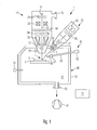
- Figure 1 is a schematic illustration of a system for supplying at least one particle beam and at least one process gas to a processing location.
- the system 1 can be used for processing an object 3 mounted on an object mount 5 such that a region of the object 3 which is to be processed is located at or close to a processing location 7 of the system 1.
- the processing system 1 of the illustrated embodiment comprises two particle beam columns 11 and 13, wherein each particle beam column 11, 13 generates a particle beam 12 and 15, respectively, wherein both particle beams 12, 15 can be directed to the processing location 7.
- the particle beam column 11 is an electron beam column wherein the generated particle beam 12 is an electron beam
- the particle beam column 13 is an ion beam column, wherein the particle beam 15 is an ion beam.
- the object mount 5 can be configured such that it can displace the object relative to the processing location 7 in three different directions in order to be able to process plural different selectable regions on the surface of the object 3 with the particle beams 12 and 15. Further, the object mount 5 can be configured to change an orientation of the object 3 relative to the particle beams 12 and 15.
- the electron beam column 11 comprises an electron source 19 having electrodes 21 for extracting an electron beam from a cathode of the electron source and to accelerate the electrons of the beam.
- the electron beam column 11 further comprises a condenser lens system 23 for shaping an electron beam 12, and an objective lens 25 for focusing the electron beam 12 at the processing location 7.
- Beam deflectors 27 are provided to change a location of incidence of the electron beam 12 on the object 3, such that the beam can be scanned across the object surface, wherein a detector 29 located within the electron beam column or a detector 31 located adjacent to the electron beam column 11 can be used to detect particles released from the object, such as secondary electrons and backscattered electrons. Detection signals of the detector 29, 31 can be used to generate an electron microscopic image of the region of the object scanned with the electron beam.
- the ion beam column 13 comprises an ion source 33 and electrodes 35 for shaping and accelerating the ion beam 15.
- Beam deflectors 37 and focusing coils or focusing electrodes 39 are used to focus the ion beam 15 on the processing location 7 and to scan the ion beam across the object 3.
- the system 1 further comprises a vacuum enclosure 49 having an enclosure wall 51 surrounding the processing location 7 such that the processing location 7 is located within a vacuum volume 53.
- a vacuum pump 56 is connected to the vacuum enclosure 49 via a pump port 55 in order to evacuate the vacuum volume 53.
- Front ends of the particle beam columns 11, 13 project into the vacuum volume 53 and are sealed relative to the enclosure wall 51.
- the particle beam columns 11 and 13 may have additional pump ports 75 for evacuating an interior of the beam columns, wherein the additional ports 75 can be connected to vacuum pump 56 or additional vacuum pumps.
- the system 1 further comprises a gas supply system 61 for supplying at least one process gas to the processing location 7.
- Figure 1 schematically shows a gas reservoir 63 located outside of the vacuum enclosure 49, a gas conduit 65 traversing the wall 51 of the vacuum enclosure 49, a valve 67 and a pipe 69 having an end positioned close to the processing location 7.
- the gas reservoir 63 can be located within the vacuum enclosure 49 such that the gas conduit 65 does not traverse the wall 51 of the vacuum enclosure 49 and corresponding vacuum seals can be avoided.
- the gas supply system 61 may include a positioning system (not shown in Figure 1 ) configured to position the end of the pipe 69 relative to the processing location 7.
- a positioning system (not shown in Figure 1 ) configured to position the end of the pipe 69 relative to the processing location 7.
- the valve 67 is controlled by a controller 71 in order to allow a process gas stored in the reservoir 63 to flow towards the processing location 7.
- the process gas can be activated by the ion beam 15 or the electron beam 12 in order to achieve a deposition of material on the object at the processing location 7 or a region close to the processing location, or to remove material from the object 3.
- the controller 7 may further control the beam deflectors 27 and 37 in order to direct the particle beams 12 and 15, respectively, to selectable different locations on the surface of the object 3 in order to change the location where the deposition of material or the removal of material occurs due to the activation of the supplied process gas with the particle beams.
- the system 1 further comprises a vacuum sensor 73 for detecting the gas pressure in the vacuum volume 53 and supplying a pressure signal to the controller 71, wherein the pressure signal is indicative of the gas pressure within the vacuum volume 53.
- FIG. 2 is a schematic representation illustrating some details of the gas supply system 61.
- the gas supply system 61 comprises three gas reservoirs 63 1 , 63 2 , 63 3 storing inventories of three different process gases. First ends 75 1 , 75 2 , 75 3 of gas conduits 65 1 , 65 2 , 65 3 are connected to the reservoirs 63 1 , 63 2 , 63 3 .
- Each of the reservoirs may comprise it's own block valve, or a respective block valve 76 1 , 76 2 , 76 3 can be provided between the reservoirs 63 1 , 63 2 , 63 3 and first ends 75 1 , 75 2 , 75 3 of the gas conduits 65 1 , 65 2 , 65 3 .
- the block valves can be operated by hand, or they can be opened by the controller 71 in order to start up the operation of the gas supply system 61, and they can be closed in order to stop the operation of the gas supply system 61.
- Valves 67 1 , 67 2 , 67 3 ' are connected to second ends 77 1 , 77 2 , 77 3 of the gas conduits 65 1 , 65 2 , 65 3 opposite to the first ends 75 1 , 75 2 , 75 3 .
- the valves 67 1 , 67 2 , 67 3 are configured to selectively allow and prevent a flow of gas through the ends 77 1 , 77 2 , 77 3 of the gas conduits 65 1 , 65 2 , 65 3 and through the respective valves 67 1 , 67 2 , 67 3 .
- valves 67 1 , 67 2 , 67 3 are magnet valves, each comprising a coil magnet 79 1 , 79 2 , 79 3 having terminals 80 1 , 80 2 , 80 3 connected to the controller 71 such that the controller 71 may supply activation currents to the coils 79 in order to selectively open and close the valves.
- the pipe 69 has a first end 81 located close to the processing location 7, and a second end 83 connected to a manifold 65 connected to the valves 67 1 , 67 2 , 67 3 .
- the upper portion of Figure 3 shows a graph illustrating a control of one of the valves 67 1 , 67 2 , 67 3 by the controller 71 in dependence of time t.
- the graph illustrates switching of the system 1 from a first mode of operation to a second mode of operation at a time 101 and from the second mode of operation back to the first mode of operation at a time 103.
- the first mode of operation in which the system is set before time 101 has a duration 102 which may amount to more than 1 second, plural seconds or even hours.
- the second mode of operation in which the system is between times 101 and 103 has a duration 104 which may amount to more than 0.1 seconds, more than 1 second or even plural minutes.
- process gas is not supplied to the processing location such that the valve is in the closed position indicated by “closed” in Figure 3 .
- process gas is supplied to the processing location, and the valve is temporally in the open position, indicated by "open”, in Figure 3 during the period 104.
- the valve is alternately opened and closed in cycles during the second mode of operation 104.
- the cycles have a duration 105.
- all cycles have a same duration 105. It is, however, also possible that different cycles have different durations.
- the valve In each cycle, the valve is open during a period 107 and closed during a period 108.
- a ratio of the first duration 107 in which the valve is open and the second duration 108 in which the valve is closed can be determined for each cycle 105. Such ratio can also be referred to as a duty cycle.
- the duty cycle is increased cycle by cycle until it reaches a stationary value in order to maintain a constant flow of process gas towards the processing location in the second mode of operation.
- the value of the ratio or duty cycle at the beginning of the second mode of operation can be smaller than 0.2, 0.4 or 0.6 times the stationary value used to supply process gas for a longer period of time.
- the time in which the duty cycle is increased at the beginning of the second mode of operation may amount to 0.5 seconds, 1 second, 2 seconds or 5 seconds, for example.
- the duty cycle can be regarded as stationary if its value does not change by more than 10% within a period of 2 seconds or more than 5 seconds, for example.
- the duration of the cycles 105 can be short, such that more than 5 cycles, more than 10 cycles or more than 20 cycles are performed at the beginning of the second mode of operation until the duty cycle reaches its stationary value.
- the duration of one cycle 105 can be shorter than 1 second, shorter than 0.5 seconds or shorter than 0.1 seconds, for example.
- the gas pressure within the reservoir and within the gas conduit immediately upstream of the valve is greater immediately at the beginning of the second mode of operation than at later times at which the process gas is supplied to the processing location using a constant duty cycle.
- the gas may be generated by sublimation from a solid state material within the gas reservoir at a limited rate. If the first mode of operation in which process gas is not supplied to the processing location has a significant duration, a substantial amount of process gas may accumulate within the reservoir and the gas conduit, resulting in an increased gas pressure which will be reduced as soon as the valve is opened and gas can escape from the reservoir and the gas conduit through the pipe towards the processing location.
- the gas conduit provides a resistance against the gas flow such that the gas pressure at the valve 67 is lower when a gas flow through the gas conduit 65 occurs during the second mode of operation as compared to the gas pressure at the valve at the end of the first mode of operation where a gas flow does not occur.
- four cycles 105 are shown at the beginning of the second mode of operation at time 101.
- the ratio between periods 107 and 108 is continuously increased in these four cycles.
- the number of four cycles is used for illustrative purposes only and a higher number of cycles in which the ratio is increased can be used in practice.
- the increase of the ratio does not necessarily occur continuously, i.e. strictly monotonically. It is possible that the ratio is increased step by step wherein the ratio is maintained constant between steps. It is further possible to reduce the ratio during a short period of time.
- the duty cycle is changed with time such that the vacuum sensor 73 generates a predetermined pressure signal.
- the time dependence of the amount of the pressure signal P is shown in the lower portion of Figure 3 .
- the pressure signal P generated by the pressure sensor 73 is at a low value 113 in the first mode of operation 102.
- the pressure value P will still be at the low value 113 since the process gas supplied into the processing location has not yet reached the pressure sensor.
- An increase of the pressure value P can be detected subsequent to a later time 117.
- the controller starts to adjust the ratio between the durations 107 and 108, i.e. the duty cycle of the valve 67, based on the pressure signal P at an even later time 119.
- the duty cycle is controlled such that the pressure signal P assumes a predetermined value 115 which has been proven advantageous in preceding experiments, for example.
- Figure 3 shows that the duration of the last cycle in the second mode of operation is shorter than the duration of the penultimate cycle 105 since the valve is closed at time 103 when the system is switched from the second mode of operation back to the first mode of operation.
- the controlling of a valve as illustrated with reference to Figure 3 above can be applied to each of the valves 67 1 , 67 2 , 67 3 shown in Figure 2 .
- the number of three gas reservoirs, gas conduits and valves is an exemplary number used for illustrative purposes.
- the controlling of the valve illustrated with reference to Figure 3 can be also applied to gas supply systems having one or two gas reservoirs or four and more gas reservoirs.
- the controlling of the valve illustrated with reference to Figure 3 above can be applied to valves of two or more gas supply systems which are configured separate from each other and wherein each gas supply system has its own pipe provided between a valve and the processing location.
- Figure 4 illustrates a method of controlling two different valves using the controller 71 in order to supply a mixture of two process gases to the processing location 7.
- the controlling of a first valve in dependence of time is shown in the upper portion of Figure 4
- the controlling of a second valve in dependence of time is shown in the lower portion of Figure 4 , wherein "open” indicates the open position of the respective valve and "closed” indicates the closed position of the respective valve.
- each cycle 129 includes a first portion having a duration 123 in which the first valve is open and the second valve is closed, a second portion of a duration 125 in which the first valve is closed and the second valve is open, and two third portions having a duration 127 in which both valves are closed.
- the two valves are alternately opened and closed, accordingly.
- Figure 4 shows two different settings of a ratio obtained by dividing the duration 123 by the duration 125 in the left and right portions, respectively. In the left portion of Figure 4 this ratio is greater than in the right portion of Figure 4 .
- the ratio of the durations 123 and 125 determines the mixture ratio of the process gases supplied to the processing location via the two valves.
- a desired mixture ratio of the process gases can be adjusted by changing the ratio of the periods 123 and 125 as shown above.
- the alternating control of the valves has an advantage in that the two process gases do not mix or do not substantially mix in the manifold 85 and the pipe 69 such that gas depositions resulting from a direct contact between different gases can be avoided or reduced within the manifold 85 and pipe 69.
- a mixing of different gases already in the manifold 85 and pipe 69 can be further reduced by increasing the duration of the periods 127 which temporally separate the periods 123 and 125 from each other and in which both valves are closed.
- the durations 127 can be very short or even zero if depositions due to different gases getting into contact within manifold 85 and pipe 69 do not present a serious problem.
- the duty cycle can be defined as the ratio of the durations 123 and 125 in which one of the valves is open, divided by the two durations 127 in which both valves are closed.
- certain properties of the gas reservoir and the gas conduit may change during operation, and the duty cycles can be adjusted to achieve a constant flow of gas towards the processing location.
- the first duration 127 between duration 123 and duration 125 can be maintained constant, while the second duration 127 between the duration 125 and the end of the cycle 129 is changed. If the sum of the durations 127 is increased while the durations 123 and 125 are maintained equal, the ratio of the sum of the two durations 123 and 125 divided by the sum of the two durations 127 becomes smaller and the gas flow towards the processing location is reduced.
- This example shows that the gas flow towards the processing location and the gas pressure within the vacuum volume 53 can be adjusted by changing the duty cycle also when two or more process gases are used.
- the pressure signal generated by the vacuum sensor 53 can be used as illustrated with reference to Figure 3 above in order to change the duty cycle based on the pressure value.
- Figure 4 illustrates the alternating control of only two valves
- the same principles of avoiding gas mixtures already in the manifold or the pipe can be applied to three or more valves, wherein periods are provided in which only one valve is open and the remaining valves are closed, wherein these periods can be separated by additional time periods in which all valves are closed.
- a common heater for the gas conduits 65 1 , 65 2 , 65 3 and valves 67 1 , 67 2 , 67 3 is indicated by a rectangle 141 in Figure 2 .
- the common heater can be implemented, for example, by a common carrier to which the gas conduits and valves are thermally connected and wherein electric energy can be supplied from the controller 71 to the common carrier via terminals 143 in order to commonly heat the gas conduits and valves.
- the heating of the gas conduits and valves is provided for avoiding depositions of process gases within the gas conduits and valves.
- the reservoir 63 1 provides fluorine as the process gas, while one or both of the remaining reservoirs 63 2 , 63 3 provide a process gas which is different from fluorine.
- these other process gases may contain Pt, W, SiO 2 , Au, J, C, O 2 , N 2 and H 2 O.
- a reservoir containing fluorine as a process gas is typically cooled, and also gas conduits supplying fluorine to a gas valve are conventionally cooled, or at least not heated.
- the gas conduit 65 1 supplying the process gas fluorine to the valve 67 1 is commonly heated together with the other gas conduits and valves.
- the inventors have found that it is advantageous to actively cool the gas reservoir providing fluorine, since fluorine is stored in a solid state within the reservoir and is generated by sublimation from the solid state.
- fluorine is in its gaseous state within the gas conduit 65 1 downstream of the block valve 76 1 such that a warming of the process gas within the gas conduit 65 1 has no disadvantage.
- an active cooling of the reservoir of fluorine or other process gases which are conventionally cooled in their reservoirs is no longer necessary since the control of the gas flow can be achieved by changing the duty cycle.
- Passive cooling of the reservoir storing fluorine using water or circulation of air can be sufficient. In particular, such passive cooling does not require controlling.
- process gases used in practice are provided below:
- Phenantrene C 14 H 10 C 9 H 16 Pt having a dissociation temperature of about 89° Celsius to 100° Celsius can be stored in a reservoir at temperatures from about 60° Celsius to about 85° Celsius and used for depositing Carbon (C).
- Dimethyl(acetylacetonat)gold(III) (CH 3 ) 2 (C 5 H 7 O 2 )Au(III) having a dissociation temperature of about 80° Celsius to 82° Celsius can be stored in a reservoir at temperatures from about 50° Celsius to about 75° Celsius and used for depositing Gold (Au).
- PMCPS 2,4,6,8,10-Pentamethylcyclopentasiloxane having a dissociation temperature of more than 120° Celsius
- PMCPS 2,4,6,8,10-Pentamethylcyclopentasiloxane
- Diacetoxy-di-tert-butoxysilane C 12 H 24 O 6 Si having a dissociation temperature of more than 120° Celsius can be stored in a reservoir at temperatures from about 20° Celsius to about 50° Celsius and used for depositing an insulator SiO 2 .
- Xenondifluorid (XeF 2 ) having a dissociation temperature of about 180° Celsius can be stored in a reservoir at temperatures from about 1° Celsius to about 35° Celsius and used for transporting fluorine (F) to the processing location.
- Magnesiumsulfateheptahydrat having a dissociation temperature of about 150° Celsius can be stored in a reservoir at temperatures from about 20° Celsius to about 35° Celsius and used for transporting water (H 2 O) to the processing location.
- Oxygen (O 2 ) having a dissociation temperature of more than 120° Celsius can be stored in a reservoir at temperatures from about 20° Celsius to about 100° Celsius and used for transporting Oxygen (O 2 ) to the processing location.
- Nitrogen (N 2 ) having a dissociation temperature of more than 120° Celsius can be stored in a reservoir at temperatures from about 20° Celsius to about 100° Celsius and used for transporting Nitrogen (N 2 ) to the processing location.
Landscapes
- Engineering & Computer Science (AREA)
- Chemical & Material Sciences (AREA)
- Analytical Chemistry (AREA)
- Physics & Mathematics (AREA)
- Plasma & Fusion (AREA)
- Mechanical Engineering (AREA)
- General Engineering & Computer Science (AREA)
- Chemical Vapour Deposition (AREA)
- Feeding, Discharge, Calcimining, Fusing, And Gas-Generation Devices (AREA)
Priority Applications (1)
| Application Number | Priority Date | Filing Date | Title |
|---|---|---|---|
| EP18165410.4A EP3373323B1 (de) | 2012-01-23 | 2013-01-23 | System zum zuführen von mehreren reaktiven prozessgasen zu einer verarbeitungsstelle eines teilchenstrahlgeräts |
Applications Claiming Priority (1)
| Application Number | Priority Date | Filing Date | Title |
|---|---|---|---|
| DE201210001267 DE102012001267A1 (de) | 2012-01-23 | 2012-01-23 | Partikelstrahlsystem mit Zuführung von Prozessgas zu einem Bearbeitungsort |
Related Child Applications (2)
| Application Number | Title | Priority Date | Filing Date |
|---|---|---|---|
| EP18165410.4A Division EP3373323B1 (de) | 2012-01-23 | 2013-01-23 | System zum zuführen von mehreren reaktiven prozessgasen zu einer verarbeitungsstelle eines teilchenstrahlgeräts |
| EP18165410.4A Division-Into EP3373323B1 (de) | 2012-01-23 | 2013-01-23 | System zum zuführen von mehreren reaktiven prozessgasen zu einer verarbeitungsstelle eines teilchenstrahlgeräts |
Publications (3)
| Publication Number | Publication Date |
|---|---|
| EP2618361A2 true EP2618361A2 (de) | 2013-07-24 |
| EP2618361A3 EP2618361A3 (de) | 2015-07-22 |
| EP2618361B1 EP2618361B1 (de) | 2018-05-23 |
Family
ID=47623905
Family Applications (2)
| Application Number | Title | Priority Date | Filing Date |
|---|---|---|---|
| EP18165410.4A Active EP3373323B1 (de) | 2012-01-23 | 2013-01-23 | System zum zuführen von mehreren reaktiven prozessgasen zu einer verarbeitungsstelle eines teilchenstrahlgeräts |
| EP13000334.6A Active EP2618361B1 (de) | 2012-01-23 | 2013-01-23 | Verfahren zum zuführen von mehreren reaktiven prozessgasen zu einer verarbeitungsstelle eines teilchenstrahlgeräts |
Family Applications Before (1)
| Application Number | Title | Priority Date | Filing Date |
|---|---|---|---|
| EP18165410.4A Active EP3373323B1 (de) | 2012-01-23 | 2013-01-23 | System zum zuführen von mehreren reaktiven prozessgasen zu einer verarbeitungsstelle eines teilchenstrahlgeräts |
Country Status (4)
| Country | Link |
|---|---|
| US (1) | US8969835B2 (de) |
| EP (2) | EP3373323B1 (de) |
| JP (1) | JP6231280B2 (de) |
| DE (1) | DE102012001267A1 (de) |
Families Citing this family (13)
| Publication number | Priority date | Publication date | Assignee | Title |
|---|---|---|---|---|
| DE102014014572B4 (de) | 2014-09-30 | 2023-08-17 | Carl Zeiss Microscopy Gmbh | Verfahren zum Strukturieren eines Objekts mit Hilfe eines Partikelstrahlgeräts |
| DE102015204091B4 (de) | 2015-03-06 | 2023-06-07 | Carl Zeiss Microscopy Gmbh | Verfahren und Vorrichtungen zur Ladungskompensation |
| KR102873439B1 (ko) | 2021-02-18 | 2025-10-20 | 칼 짜이스 에스엠테 게엠베하 | 하전 입자에 의해 샘플의 관심 구역을 검사, 수정 또는 분석하는 시스템, 샘플의 관심 구역을 검사, 수정 또는 분석하는 시스템의 세트 및 하전 입자에 의해 샘플의 관심 구역을 검사, 수정 또는 분석하는 방법 |
| US12044638B2 (en) | 2021-02-18 | 2024-07-23 | Carl Zeiss Smt Gmbh | System to inspect, modify or analyze a region of interest of a sample by charged particles, set of systems to inspect, modify or analyze a region of interest of a sample and method to inspect, modify or analyze a region of interest of a sample by charged particles |
| WO2022184760A1 (en) | 2021-03-03 | 2022-09-09 | Carl Zeiss Smt Gmbh | Gas injection subsystem for use in an inspection system to inspect a sample by use of charged particles and inspection system having such gas injection subsystem |
| DE102021202941A1 (de) | 2021-03-25 | 2022-09-29 | Carl Zeiss Smt Gmbh | Gasinjektionssubsystem zur Verwendung in einem Untersuchungssystem zum Untersuchen einer Probe unter Verwendung von geladenen Teilchen und Untersuchungssystem, das ein solches Gasinjektionssubsystem aufweist |
| DE102021132833A1 (de) | 2021-12-13 | 2023-06-15 | Carl Zeiss Microscopy Gmbh | Gaszuführungseinrichtung, System mit einer Gaszuführungseinrichtung sowie Teilchenstrahlgerät mit einer Gaszuführungseinrichtung oder dem System |
| DE102021132834B4 (de) | 2021-12-13 | 2024-08-08 | Carl Zeiss Microscopy Gmbh | Gasreservoir, Gaszuführungseinrichtung mit einem Gasreservoir und Teilchenstrahlgerät mit einer Gaszuführungseinrichtung |
| DE102021132832A1 (de) | 2021-12-13 | 2023-06-15 | Carl Zeiss Microscopy Gmbh | Gaszuführungseinrichtung, Teilchenstrahlgerät mit einer Gaszuführungseinrichtung sowie Verfahren zum Betrieb der Gaszuführungseinrichtung und des Teilchenstrahlgeräts |
| DE102021214447A1 (de) | 2021-12-15 | 2023-06-15 | Carl Zeiss Smt Gmbh | Elektronenmikroskop zum Untersuchen einer Probe |
| WO2023151946A1 (en) | 2022-02-10 | 2023-08-17 | Carl Zeiss Smt Gmbh | Method to investigate a semiconductor sample layer by layer and investigation device to perform such method |
| DE102022118006B3 (de) | 2022-07-19 | 2023-11-16 | Carl Zeiss Microscopy Gmbh | Verfahren zum Bearbeiten einer Probe, Teilchenstrahlsystem und Computerprogrammprodukt |
| CZ310675B6 (cs) * | 2023-02-19 | 2026-04-22 | Tescan Group, A.S. | Zařízení s fokusovaným svazkem nabitých částic a způsob opracování či zobrazování vzorků |
Citations (1)
| Publication number | Priority date | Publication date | Assignee | Title |
|---|---|---|---|---|
| US20060284090A1 (en) | 2002-02-25 | 2006-12-21 | Carl Zeiss Nts Gmbh | Material processing system and method |
Family Cites Families (32)
| Publication number | Priority date | Publication date | Assignee | Title |
|---|---|---|---|---|
| JP2715423B2 (ja) * | 1988-01-27 | 1998-02-18 | 日本電気株式会社 | 化学蒸着法による薄膜形成装置 |
| JPH02248390A (ja) * | 1989-03-22 | 1990-10-04 | Nec Corp | 分子線発生装置 |
| JPH09184080A (ja) * | 1995-12-27 | 1997-07-15 | Vacuum Metallurgical Co Ltd | 超微粒子による薄膜形成方法、およびその薄膜形成装置 |
| JP3505987B2 (ja) * | 1997-12-22 | 2004-03-15 | 日新電機株式会社 | シリコン系薄膜の形成方法及び成膜装置 |
| DE19851622A1 (de) * | 1998-11-09 | 2000-05-18 | Fraunhofer Ges Forschung | Verfahren zum Untersuchen und/oder zum Modifizieren von Oberflächenstrukturen einer Probe |
| US6157662A (en) * | 1999-02-12 | 2000-12-05 | Lambda Physik Gmbh | F2 (157nm) laser employing neon as the buffer gas |
| JP2000282241A (ja) * | 1999-04-01 | 2000-10-10 | Matsushita Electric Ind Co Ltd | 多層薄膜の製造方法 |
| WO2001003145A1 (en) * | 1999-07-02 | 2001-01-11 | Applied Materials, Inc. | Apparatus and method for examining specimen with a charged particle beam |
| JP4350333B2 (ja) * | 1999-11-22 | 2009-10-21 | エスアイアイ・ナノテクノロジー株式会社 | 化合物蒸気吹付け装置およびそれを用いた集束イオンビーム装置 |
| JP3736322B2 (ja) * | 2000-04-26 | 2006-01-18 | 昭和電工株式会社 | 気相成長装置 |
| DE10042098A1 (de) * | 2000-08-26 | 2002-03-14 | Deutsche Telekom Ag | Gasversorgung für Additive Lithographie |
| JP2002129337A (ja) * | 2000-10-24 | 2002-05-09 | Applied Materials Inc | 気相堆積方法及び装置 |
| JP4178741B2 (ja) | 2000-11-02 | 2008-11-12 | 株式会社日立製作所 | 荷電粒子線装置および試料作製装置 |
| DE10208043B4 (de) | 2002-02-25 | 2011-01-13 | Carl Zeiss Nts Gmbh | Materialbearbeitungssystem und Materialbearbeitungsverfahren |
| US6846516B2 (en) * | 2002-04-08 | 2005-01-25 | Applied Materials, Inc. | Multiple precursor cyclical deposition system |
| EP1774538A4 (de) * | 2004-07-29 | 2012-06-06 | Omniprobe Inc | Multiples gasinjektionssystem für strahlinstrumente geladener teilchen |
| US7846499B2 (en) * | 2004-12-30 | 2010-12-07 | Asm International N.V. | Method of pulsing vapor precursors in an ALD reactor |
| JP4627682B2 (ja) | 2005-05-27 | 2011-02-09 | 株式会社日立ハイテクノロジーズ | 試料作製装置および方法 |
| US7692163B2 (en) * | 2006-01-31 | 2010-04-06 | Kabushiki Kaisha Toshiba | Charged particle beam apparatus, defect correcting method, etching method, deposition method, and charge preventing method |
| DE602006015768D1 (de) * | 2006-02-23 | 2010-09-09 | Integrated Circuit Testing | Teilchenstrahlgerät mit Ozon-Quelle |
| US20070224708A1 (en) * | 2006-03-21 | 2007-09-27 | Sowmya Krishnan | Mass pulse sensor and process-gas system and method |
| US20080078745A1 (en) * | 2006-09-29 | 2008-04-03 | Zyvex Corporation | RF Coil Plasma Generation |
| JP2008218866A (ja) * | 2007-03-07 | 2008-09-18 | Elpida Memory Inc | パターン形成方法およびパターン形成装置 |
| JP5001757B2 (ja) * | 2007-08-31 | 2012-08-15 | シーケーディ株式会社 | 流体混合システム及び流体混合装置 |
| DE102007054074A1 (de) | 2007-11-13 | 2009-05-14 | Carl Zeiss Nts Gmbh | System zum Bearbeiten eines Objekts |
| TWI479570B (zh) | 2007-12-26 | 2015-04-01 | 奈華科技有限公司 | 從樣本移除材料之方法及系統 |
| US8394454B2 (en) * | 2008-03-08 | 2013-03-12 | Omniprobe, Inc. | Method and apparatus for precursor delivery system for irradiation beam instruments |
| DE102008037951B4 (de) | 2008-08-14 | 2018-02-15 | Nawotec Gmbh | Verfahren und Vorrichtung zum elektronenstrahlinduzierten Ätzen von mit Gallium verunreinigten Schichten |
| US20100068408A1 (en) | 2008-09-16 | 2010-03-18 | Omniprobe, Inc. | Methods for electron-beam induced deposition of material inside energetic-beam microscopes |
| US8278224B1 (en) * | 2009-09-24 | 2012-10-02 | Novellus Systems, Inc. | Flowable oxide deposition using rapid delivery of process gases |
| CN102597312B (zh) * | 2009-11-16 | 2015-08-05 | Fei公司 | 用于束处理系统的气体传输 |
| US9719169B2 (en) * | 2010-12-20 | 2017-08-01 | Novellus Systems, Inc. | System and apparatus for flowable deposition in semiconductor fabrication |
-
2012
- 2012-01-23 DE DE201210001267 patent/DE102012001267A1/de not_active Ceased
-
2013
- 2013-01-22 US US13/746,560 patent/US8969835B2/en active Active
- 2013-01-23 JP JP2013010160A patent/JP6231280B2/ja active Active
- 2013-01-23 EP EP18165410.4A patent/EP3373323B1/de active Active
- 2013-01-23 EP EP13000334.6A patent/EP2618361B1/de active Active
Patent Citations (1)
| Publication number | Priority date | Publication date | Assignee | Title |
|---|---|---|---|---|
| US20060284090A1 (en) | 2002-02-25 | 2006-12-21 | Carl Zeiss Nts Gmbh | Material processing system and method |
Also Published As
| Publication number | Publication date |
|---|---|
| US8969835B2 (en) | 2015-03-03 |
| EP2618361A3 (de) | 2015-07-22 |
| US20130187064A1 (en) | 2013-07-25 |
| EP3373323B1 (de) | 2020-12-30 |
| JP6231280B2 (ja) | 2017-11-15 |
| EP3373323A3 (de) | 2018-12-05 |
| EP3373323A2 (de) | 2018-09-12 |
| JP2013167018A (ja) | 2013-08-29 |
| EP2618361B1 (de) | 2018-05-23 |
| DE102012001267A1 (de) | 2013-07-25 |
Similar Documents
| Publication | Publication Date | Title |
|---|---|---|
| EP3373323B1 (de) | System zum zuführen von mehreren reaktiven prozessgasen zu einer verarbeitungsstelle eines teilchenstrahlgeräts | |
| KR20210018761A (ko) | 냉각 장치를 포함한 히터 어셈블리 및 이를 사용하는 방법 | |
| CN105702547B (zh) | 离子注入系统及方法 | |
| CN107608396B (zh) | 气体供给系统、基板处理系统及气体供给方法 | |
| US20170338075A1 (en) | Ion implantation processes and apparatus | |
| US10840070B2 (en) | Ion beam device and cleaning method for gas field ion source | |
| KR20210062680A (ko) | 질량 분석기 및 질량 분석법에 의한 가스 분석 방법 | |
| JP2014165169A (ja) | 真空チャンバをクリーニングする方法及びシステム | |
| US12068135B2 (en) | Fast gas exchange apparatus, system, and method | |
| JP5416351B2 (ja) | プラズマガン成膜装置及びその運転方法 | |
| KR20240138090A (ko) | 이온 소스용 유압 공급 시스템 | |
| EP2593580B1 (de) | System und verfahren zur druckregelung bei einer prozesskammer | |
| JP2022106692A (ja) | ガリウムを用いたイオン注入プロセスおよび装置 | |
| CN108977779B (zh) | 溅射装置 | |
| TW202421828A (zh) | 材料沉積系統設備維護 | |
| JP7507067B2 (ja) | スパッタリング装置 | |
| KR20200010876A (ko) | 기판 처리 장치 및 방법 | |
| Strzyzewski et al. | Magnetic filters in UHV arc-discharges: constructions, field modelling and tests of efficiency | |
| JP3168912U (ja) | ガス供給装置 | |
| KR20250091535A (ko) | Mfc 검증 장치 및 이를 포함하는 기판 처리 장치 | |
| KR100599924B1 (ko) | 반응성 스퍼터링용 장치 | |
| KR20150105152A (ko) | 박막 형성 장치 |
Legal Events
| Date | Code | Title | Description |
|---|---|---|---|
| PUAI | Public reference made under article 153(3) epc to a published international application that has entered the european phase |
Free format text: ORIGINAL CODE: 0009012 |
|
| AK | Designated contracting states |
Kind code of ref document: A2 Designated state(s): AL AT BE BG CH CY CZ DE DK EE ES FI FR GB GR HR HU IE IS IT LI LT LU LV MC MK MT NL NO PL PT RO RS SE SI SK SM TR |
|
| AX | Request for extension of the european patent |
Extension state: BA ME |
|
| RIC1 | Information provided on ipc code assigned before grant |
Ipc: H01J 37/305 20060101AFI20141218BHEP |
|
| PUAL | Search report despatched |
Free format text: ORIGINAL CODE: 0009013 |
|
| AK | Designated contracting states |
Kind code of ref document: A3 Designated state(s): AL AT BE BG CH CY CZ DE DK EE ES FI FR GB GR HR HU IE IS IT LI LT LU LV MC MK MT NL NO PL PT RO RS SE SI SK SM TR |
|
| AX | Request for extension of the european patent |
Extension state: BA ME |
|
| RIC1 | Information provided on ipc code assigned before grant |
Ipc: H01J 37/305 20060101AFI20150618BHEP Ipc: H01J 37/02 20060101ALI20150618BHEP |
|
| 17P | Request for examination filed |
Effective date: 20160122 |
|
| RBV | Designated contracting states (corrected) |
Designated state(s): AL AT BE BG CH CY CZ DE DK EE ES FI FR GB GR HR HU IE IS IT LI LT LU LV MC MK MT NL NO PL PT RO RS SE SI SK SM TR |
|
| STAA | Information on the status of an ep patent application or granted ep patent |
Free format text: STATUS: EXAMINATION IS IN PROGRESS |
|
| 17Q | First examination report despatched |
Effective date: 20170222 |
|
| GRAP | Despatch of communication of intention to grant a patent |
Free format text: ORIGINAL CODE: EPIDOSNIGR1 |
|
| STAA | Information on the status of an ep patent application or granted ep patent |
Free format text: STATUS: GRANT OF PATENT IS INTENDED |
|
| INTG | Intention to grant announced |
Effective date: 20171211 |
|
| GRAS | Grant fee paid |
Free format text: ORIGINAL CODE: EPIDOSNIGR3 |
|
| GRAA | (expected) grant |
Free format text: ORIGINAL CODE: 0009210 |
|
| STAA | Information on the status of an ep patent application or granted ep patent |
Free format text: STATUS: THE PATENT HAS BEEN GRANTED |
|
| AK | Designated contracting states |
Kind code of ref document: B1 Designated state(s): AL AT BE BG CH CY CZ DE DK EE ES FI FR GB GR HR HU IE IS IT LI LT LU LV MC MK MT NL NO PL PT RO RS SE SI SK SM TR |
|
| REG | Reference to a national code |
Ref country code: GB Ref legal event code: FG4D |
|
| REG | Reference to a national code |
Ref country code: CH Ref legal event code: EP |
|
| REG | Reference to a national code |
Ref country code: IE Ref legal event code: FG4D |
|
| REG | Reference to a national code |
Ref country code: AT Ref legal event code: REF Ref document number: 1002176 Country of ref document: AT Kind code of ref document: T Effective date: 20180615 |
|
| REG | Reference to a national code |
Ref country code: DE Ref legal event code: R096 Ref document number: 602013037704 Country of ref document: DE |
|
| REG | Reference to a national code |
Ref country code: NL Ref legal event code: FP |
|
| REG | Reference to a national code |
Ref country code: LT Ref legal event code: MG4D |
|
| PG25 | Lapsed in a contracting state [announced via postgrant information from national office to epo] |
Ref country code: LT Free format text: LAPSE BECAUSE OF FAILURE TO SUBMIT A TRANSLATION OF THE DESCRIPTION OR TO PAY THE FEE WITHIN THE PRESCRIBED TIME-LIMIT Effective date: 20180523 Ref country code: ES Free format text: LAPSE BECAUSE OF FAILURE TO SUBMIT A TRANSLATION OF THE DESCRIPTION OR TO PAY THE FEE WITHIN THE PRESCRIBED TIME-LIMIT Effective date: 20180523 Ref country code: BG Free format text: LAPSE BECAUSE OF FAILURE TO SUBMIT A TRANSLATION OF THE DESCRIPTION OR TO PAY THE FEE WITHIN THE PRESCRIBED TIME-LIMIT Effective date: 20180823 Ref country code: FI Free format text: LAPSE BECAUSE OF FAILURE TO SUBMIT A TRANSLATION OF THE DESCRIPTION OR TO PAY THE FEE WITHIN THE PRESCRIBED TIME-LIMIT Effective date: 20180523 Ref country code: NO Free format text: LAPSE BECAUSE OF FAILURE TO SUBMIT A TRANSLATION OF THE DESCRIPTION OR TO PAY THE FEE WITHIN THE PRESCRIBED TIME-LIMIT Effective date: 20180823 Ref country code: SE Free format text: LAPSE BECAUSE OF FAILURE TO SUBMIT A TRANSLATION OF THE DESCRIPTION OR TO PAY THE FEE WITHIN THE PRESCRIBED TIME-LIMIT Effective date: 20180523 |
|
| PG25 | Lapsed in a contracting state [announced via postgrant information from national office to epo] |
Ref country code: LV Free format text: LAPSE BECAUSE OF FAILURE TO SUBMIT A TRANSLATION OF THE DESCRIPTION OR TO PAY THE FEE WITHIN THE PRESCRIBED TIME-LIMIT Effective date: 20180523 Ref country code: RS Free format text: LAPSE BECAUSE OF FAILURE TO SUBMIT A TRANSLATION OF THE DESCRIPTION OR TO PAY THE FEE WITHIN THE PRESCRIBED TIME-LIMIT Effective date: 20180523 Ref country code: GR Free format text: LAPSE BECAUSE OF FAILURE TO SUBMIT A TRANSLATION OF THE DESCRIPTION OR TO PAY THE FEE WITHIN THE PRESCRIBED TIME-LIMIT Effective date: 20180824 Ref country code: HR Free format text: LAPSE BECAUSE OF FAILURE TO SUBMIT A TRANSLATION OF THE DESCRIPTION OR TO PAY THE FEE WITHIN THE PRESCRIBED TIME-LIMIT Effective date: 20180523 |
|
| REG | Reference to a national code |
Ref country code: AT Ref legal event code: MK05 Ref document number: 1002176 Country of ref document: AT Kind code of ref document: T Effective date: 20180523 |
|
| PG25 | Lapsed in a contracting state [announced via postgrant information from national office to epo] |
Ref country code: DK Free format text: LAPSE BECAUSE OF FAILURE TO SUBMIT A TRANSLATION OF THE DESCRIPTION OR TO PAY THE FEE WITHIN THE PRESCRIBED TIME-LIMIT Effective date: 20180523 Ref country code: PL Free format text: LAPSE BECAUSE OF FAILURE TO SUBMIT A TRANSLATION OF THE DESCRIPTION OR TO PAY THE FEE WITHIN THE PRESCRIBED TIME-LIMIT Effective date: 20180523 Ref country code: SK Free format text: LAPSE BECAUSE OF FAILURE TO SUBMIT A TRANSLATION OF THE DESCRIPTION OR TO PAY THE FEE WITHIN THE PRESCRIBED TIME-LIMIT Effective date: 20180523 Ref country code: RO Free format text: LAPSE BECAUSE OF FAILURE TO SUBMIT A TRANSLATION OF THE DESCRIPTION OR TO PAY THE FEE WITHIN THE PRESCRIBED TIME-LIMIT Effective date: 20180523 Ref country code: EE Free format text: LAPSE BECAUSE OF FAILURE TO SUBMIT A TRANSLATION OF THE DESCRIPTION OR TO PAY THE FEE WITHIN THE PRESCRIBED TIME-LIMIT Effective date: 20180523 Ref country code: AT Free format text: LAPSE BECAUSE OF FAILURE TO SUBMIT A TRANSLATION OF THE DESCRIPTION OR TO PAY THE FEE WITHIN THE PRESCRIBED TIME-LIMIT Effective date: 20180523 |
|
| REG | Reference to a national code |
Ref country code: DE Ref legal event code: R097 Ref document number: 602013037704 Country of ref document: DE |
|
| PG25 | Lapsed in a contracting state [announced via postgrant information from national office to epo] |
Ref country code: SM Free format text: LAPSE BECAUSE OF FAILURE TO SUBMIT A TRANSLATION OF THE DESCRIPTION OR TO PAY THE FEE WITHIN THE PRESCRIBED TIME-LIMIT Effective date: 20180523 Ref country code: IT Free format text: LAPSE BECAUSE OF FAILURE TO SUBMIT A TRANSLATION OF THE DESCRIPTION OR TO PAY THE FEE WITHIN THE PRESCRIBED TIME-LIMIT Effective date: 20180523 |
|
| PLBE | No opposition filed within time limit |
Free format text: ORIGINAL CODE: 0009261 |
|
| STAA | Information on the status of an ep patent application or granted ep patent |
Free format text: STATUS: NO OPPOSITION FILED WITHIN TIME LIMIT |
|
| 26N | No opposition filed |
Effective date: 20190226 |
|
| PG25 | Lapsed in a contracting state [announced via postgrant information from national office to epo] |
Ref country code: SI Free format text: LAPSE BECAUSE OF FAILURE TO SUBMIT A TRANSLATION OF THE DESCRIPTION OR TO PAY THE FEE WITHIN THE PRESCRIBED TIME-LIMIT Effective date: 20180523 |
|
| REG | Reference to a national code |
Ref country code: DE Ref legal event code: R119 Ref document number: 602013037704 Country of ref document: DE |
|
| PG25 | Lapsed in a contracting state [announced via postgrant information from national office to epo] |
Ref country code: MC Free format text: LAPSE BECAUSE OF FAILURE TO SUBMIT A TRANSLATION OF THE DESCRIPTION OR TO PAY THE FEE WITHIN THE PRESCRIBED TIME-LIMIT Effective date: 20180523 |
|
| REG | Reference to a national code |
Ref country code: CH Ref legal event code: PL |
|
| GBPC | Gb: european patent ceased through non-payment of renewal fee |
Effective date: 20190123 |
|
| PG25 | Lapsed in a contracting state [announced via postgrant information from national office to epo] |
Ref country code: LU Free format text: LAPSE BECAUSE OF NON-PAYMENT OF DUE FEES Effective date: 20190123 |
|
| REG | Reference to a national code |
Ref country code: BE Ref legal event code: MM Effective date: 20190131 |
|
| REG | Reference to a national code |
Ref country code: IE Ref legal event code: MM4A |
|
| PG25 | Lapsed in a contracting state [announced via postgrant information from national office to epo] |
Ref country code: FR Free format text: LAPSE BECAUSE OF NON-PAYMENT OF DUE FEES Effective date: 20190131 Ref country code: DE Free format text: LAPSE BECAUSE OF NON-PAYMENT OF DUE FEES Effective date: 20190801 |
|
| PG25 | Lapsed in a contracting state [announced via postgrant information from national office to epo] |
Ref country code: BE Free format text: LAPSE BECAUSE OF NON-PAYMENT OF DUE FEES Effective date: 20190131 Ref country code: AL Free format text: LAPSE BECAUSE OF FAILURE TO SUBMIT A TRANSLATION OF THE DESCRIPTION OR TO PAY THE FEE WITHIN THE PRESCRIBED TIME-LIMIT Effective date: 20180523 |
|
| PG25 | Lapsed in a contracting state [announced via postgrant information from national office to epo] |
Ref country code: GB Free format text: LAPSE BECAUSE OF NON-PAYMENT OF DUE FEES Effective date: 20190123 Ref country code: LI Free format text: LAPSE BECAUSE OF NON-PAYMENT OF DUE FEES Effective date: 20190131 Ref country code: CH Free format text: LAPSE BECAUSE OF NON-PAYMENT OF DUE FEES Effective date: 20190131 |
|
| PG25 | Lapsed in a contracting state [announced via postgrant information from national office to epo] |
Ref country code: IE Free format text: LAPSE BECAUSE OF NON-PAYMENT OF DUE FEES Effective date: 20190123 |
|
| PG25 | Lapsed in a contracting state [announced via postgrant information from national office to epo] |
Ref country code: TR Free format text: LAPSE BECAUSE OF FAILURE TO SUBMIT A TRANSLATION OF THE DESCRIPTION OR TO PAY THE FEE WITHIN THE PRESCRIBED TIME-LIMIT Effective date: 20180523 |
|
| PG25 | Lapsed in a contracting state [announced via postgrant information from national office to epo] |
Ref country code: MT Free format text: LAPSE BECAUSE OF NON-PAYMENT OF DUE FEES Effective date: 20190123 Ref country code: PT Free format text: LAPSE BECAUSE OF FAILURE TO SUBMIT A TRANSLATION OF THE DESCRIPTION OR TO PAY THE FEE WITHIN THE PRESCRIBED TIME-LIMIT Effective date: 20180924 |
|
| PG25 | Lapsed in a contracting state [announced via postgrant information from national office to epo] |
Ref country code: CY Free format text: LAPSE BECAUSE OF FAILURE TO SUBMIT A TRANSLATION OF THE DESCRIPTION OR TO PAY THE FEE WITHIN THE PRESCRIBED TIME-LIMIT Effective date: 20180523 |
|
| PG25 | Lapsed in a contracting state [announced via postgrant information from national office to epo] |
Ref country code: IS Free format text: LAPSE BECAUSE OF FAILURE TO SUBMIT A TRANSLATION OF THE DESCRIPTION OR TO PAY THE FEE WITHIN THE PRESCRIBED TIME-LIMIT Effective date: 20180923 |
|
| PG25 | Lapsed in a contracting state [announced via postgrant information from national office to epo] |
Ref country code: HU Free format text: LAPSE BECAUSE OF FAILURE TO SUBMIT A TRANSLATION OF THE DESCRIPTION OR TO PAY THE FEE WITHIN THE PRESCRIBED TIME-LIMIT; INVALID AB INITIO Effective date: 20130123 |
|
| PGFP | Annual fee paid to national office [announced via postgrant information from national office to epo] |
Ref country code: NL Payment date: 20220119 Year of fee payment: 10 |
|
| PG25 | Lapsed in a contracting state [announced via postgrant information from national office to epo] |
Ref country code: MK Free format text: LAPSE BECAUSE OF FAILURE TO SUBMIT A TRANSLATION OF THE DESCRIPTION OR TO PAY THE FEE WITHIN THE PRESCRIBED TIME-LIMIT Effective date: 20180523 |
|
| REG | Reference to a national code |
Ref country code: NL Ref legal event code: MM Effective date: 20230201 |
|
| PG25 | Lapsed in a contracting state [announced via postgrant information from national office to epo] |
Ref country code: NL Free format text: LAPSE BECAUSE OF NON-PAYMENT OF DUE FEES Effective date: 20230201 |
|
| PGFP | Annual fee paid to national office [announced via postgrant information from national office to epo] |
Ref country code: CZ Payment date: 20260116 Year of fee payment: 14 |