EP2618754B1 - Trägersystem für chirurgisches wirbensäuleninstrument - Google Patents
Trägersystem für chirurgisches wirbensäuleninstrument Download PDFInfo
- Publication number
- EP2618754B1 EP2618754B1 EP11752413.2A EP11752413A EP2618754B1 EP 2618754 B1 EP2618754 B1 EP 2618754B1 EP 11752413 A EP11752413 A EP 11752413A EP 2618754 B1 EP2618754 B1 EP 2618754B1
- Authority
- EP
- European Patent Office
- Prior art keywords
- collar
- sleeve
- support body
- linkage
- relative
- Prior art date
- Legal status (The legal status is an assumption and is not a legal conclusion. Google has not performed a legal analysis and makes no representation as to the accuracy of the status listed.)
- Not-in-force
Links
Images

Classifications
-
- A—HUMAN NECESSITIES
- A61—MEDICAL OR VETERINARY SCIENCE; HYGIENE
- A61B—DIAGNOSIS; SURGERY; IDENTIFICATION
- A61B17/00—Surgical instruments, devices or methods
- A61B17/56—Surgical instruments or methods for treatment of bones or joints; Devices specially adapted therefor
- A61B17/58—Surgical instruments or methods for treatment of bones or joints; Devices specially adapted therefor for osteosynthesis, e.g. bone plates, screws or setting implements
- A61B17/68—Internal fixation devices, including fasteners and spinal fixators, even if a part thereof projects from the skin
- A61B17/70—Spinal positioners or stabilisers, e.g. stabilisers comprising fluid filler in an implant
- A61B17/7074—Tools specially adapted for spinal fixation operations other than for bone removal or filler handling
- A61B17/7076—Tools specially adapted for spinal fixation operations other than for bone removal or filler handling for driving, positioning or assembling spinal clamps or bone anchors specially adapted for spinal fixation
- A61B17/7077—Tools specially adapted for spinal fixation operations other than for bone removal or filler handling for driving, positioning or assembling spinal clamps or bone anchors specially adapted for spinal fixation for moving bone anchors attached to vertebrae, thereby displacing the vertebrae
- A61B17/708—Tools specially adapted for spinal fixation operations other than for bone removal or filler handling for driving, positioning or assembling spinal clamps or bone anchors specially adapted for spinal fixation for moving bone anchors attached to vertebrae, thereby displacing the vertebrae with tubular extensions coaxially mounted on the bone anchors
-
- A—HUMAN NECESSITIES
- A61—MEDICAL OR VETERINARY SCIENCE; HYGIENE
- A61B—DIAGNOSIS; SURGERY; IDENTIFICATION
- A61B17/00—Surgical instruments, devices or methods
- A61B17/56—Surgical instruments or methods for treatment of bones or joints; Devices specially adapted therefor
- A61B17/58—Surgical instruments or methods for treatment of bones or joints; Devices specially adapted therefor for osteosynthesis, e.g. bone plates, screws or setting implements
- A61B17/68—Internal fixation devices, including fasteners and spinal fixators, even if a part thereof projects from the skin
- A61B17/70—Spinal positioners or stabilisers, e.g. stabilisers comprising fluid filler in an implant
- A61B17/7074—Tools specially adapted for spinal fixation operations other than for bone removal or filler handling
- A61B17/7076—Tools specially adapted for spinal fixation operations other than for bone removal or filler handling for driving, positioning or assembling spinal clamps or bone anchors specially adapted for spinal fixation
- A61B17/7077—Tools specially adapted for spinal fixation operations other than for bone removal or filler handling for driving, positioning or assembling spinal clamps or bone anchors specially adapted for spinal fixation for moving bone anchors attached to vertebrae, thereby displacing the vertebrae
- A61B17/7079—Tools requiring anchors to be already mounted on an implanted longitudinal or transverse element, e.g. where said element guides the anchor motion
Definitions
- the present disclosure generally relates to surgical tools and in particular to an external support with multiple components that may be controlled individually to manipulate the spine during spinal surgery.
- the human spine consists of segments known as vertebrae linked by intervertebral disks and held together by ligaments.
- Each vertebra has a somewhat cylindrical bony body (centrum), a number of winglike projections (processes), and a bony arch.
- the arches are positioned so that the space they enclose forms the vertebral canal.
- the vertebral canal houses and protects the spinal cord, and within it the spinal fluid circulates.
- Ligaments and muscles are attached to various projections of the vertebrae.
- the bodies of the vertebrae form the supporting column of the skeleton. Fused vertebra make up the sacrum and coccyx, the very bottom of the vertebral column.
- the spine is subject to abnormal curvature, injury, infections, tumor formation, arthritic disorders, and puncture or slippage of the cartilage disks.
- Modern spine surgery often involves the use of spinal stabilization/fixation procedures such as a vertebral body fusion procedure to correct or treat various acute or chronic spine disorders and/or to support the spine.
- spinal implants may be utilized to help stabilize the spine, correct deformities of the spine such as spondylolisthesis or pseudoarthrosis, facilitate fusion, or treat spinal fractures.
- Some spinal fixation systems may provide fused and/or rigid support for the affected regions of the spine.
- a spinal fixation system may include a corrective spinal implant that is attached to selected vertebrae of the spine by screws, hooks, and clamps.
- the corrective spinal implant may include spinal rods or plates that are generally parallel to the patient's back.
- the corrective spinal implant may also include transverse connecting rods that extend between neighboring spinal rods.
- Spinal fixation systems can be used to correct problems in the cervical, thoracic, and lumbar portions of the spine, and are often installed posterior to the spine on opposite sides of the spinous process and adjacent to the transverse process. Spinal fixation systems when implanted inhibit movement in the affected regions in virtually all directions.
- WO 2009/158707 A1 describes a system and method for surgical spinal correction comprising a plurality of bonescrews spinal rods, manipulators and transverse couplers.
- US 2008/077155 A describes a spinal displacement device having a first arm, a second arm and a connector.
- Dynamic spinal stabilization systems can better match a patient's anatomy than some spinal stabilization systems used to provide static support.
- a dynamic spinal stabilization system can allow at least some movement (e.g., flexion, extension, lateral bending, or torsional rotation) of the affected regions of the spine in at least some of the directions, giving the patient a greater range of motion.
- Dynamic stabilization systems can be used in scenarios in which vertebral body fusion is not desired, in which vertebral body (re)alignment is desired, and in which it is desired to support or strengthen degraded, diseased, damaged, or otherwise weakened portions of the spine.
- spinal stabilization systems include rods which can bear a portion of the forces that would otherwise be transmitted along the spine. These rods may be implanted in pairs or in other numbers along portions of the spine of interest. Some spinal stabilization systems may support a portion of the spine including only two vertebrae (and associated anatomical structures) while some spinal stabilization systems support portions of the spine extending beyond two vertebrae. Spinal stabilizations systems can be used to support various portions of the spine, including the lumbar portion of the spine and the thoracic portion of the spine.
- the rods can be attached to one or more vertebrae of the spine to provide support and stabilize, align, or otherwise treat the region of the spine of interest.
- Surgical personnel may use one or more anchor systems to attach the rods to one or more vertebrae.
- One such anchor system includes pedicle screws constructs which define slots, keyways, grooves, apertures, or other features for accepting and retaining stabilization rods which may be static, dynamic, or a combination of both. In many pedicle screw constructs, pedicle screws are placed in vertebrae selected by surgical personnel.
- translation compression or distraction
- the second vertebral body must be locked to the rod or movement will not be fixed. If a second type of manipulation (i.e., angular rotation) is required, the implants must be unlocked to allow the manipulation, which can result in the original movement being undone.
- Embodiments of a surgical instrument support system described herein do not require a spinal stabilization rod to be installed until after the movement has been completed.
- consecutive movements may be performed and held in place by various components, enabling percutaneous and minimally invasive surgery techniques to be used to correct increasingly complex deformities or treat trauma.
- a system for positioning components in a surgical procedure can include a support body to support extender sleeves that are used to manipulate the vertebrae.
- a support body collar is mounted to the support body and can translate along the support body.
- a linkage is coupled to the support body collar and can translate perpendicular (or other selected angle) to the support body collar.
- a sleeve collar is connected to the linkage by a connection that allows polyaxial rotation of the sleeve collar.
- the sleeve collar is sized to receive an extender sleeve and allow translation of the extender sleeve in the sleeve collar.
- the sleeve can be placed in a desired location and orientation relative to a patient's body.
- Locking mechanisms can be used to selectively inhibit motion of the support body collar relative to the support body, the linkage relative to the support body collar, the sleeve collar relative to the linkage and the sleeve relative to the sleeve collar.
- the surgeon can configure the system to allow only motion in selected directions while preventing undesired motion. Motion of an extender sleeve can be allowed or inhibited for each procedural step as needed or desired.
- a method not claimed for treating spinal injuries can comprise providing a rigid support body coupled to a set of extender sleeves.
- the support body provides support for the extender sleeves outside of a human body and the extender sleeves can translate and rotate relative the support body.
- the method can further comprise determining a desired longitudinal position and orientation of each of the set of extender sleeves and locking each of the set of extender sleeves in the desired longitudinal position and orientation.
- the method can further comprise advancing a set of bone anchors into vertebrae using the extender sleeves.
- the method can further comprise allowing selected translation and rotation of each extender sleeve relative to the support body while continuing to inhibit other translation and rotation relative to the support body.
- the extender sleeves can be manipulated to move selected vertebrae. The position and orientation of each of the set of extender sleeves can be locked when the selected vertebrae are in desired positions
- Embodiments of a surgical instrument support system may be beneficial in the treatment or correction of a spine having a deformity.
- the surgical instrument support system may be attached to the affected spine and one or more vertebrae may be moved individually or as a unit to correct the curvature of the spine, ensure proper positioning of vertebrae, or perform other translational or rotational adjustments until the spine has the correct curvature and alignment.
- the terms “comprises,” “comprising,” “includes,” “including,” “has,” “having” or any other variation thereof, are intended to cover a non-exclusive inclusion.
- a process, product, article, or apparatus that comprises a list of elements is not necessarily limited to only those elements but may include other elements not expressly listed or inherent to such process, article, or apparatus.
- "or” refers to an inclusive or and not to an exclusive or. For example, a condition A or B is satisfied by any one of the following: A is true (or present) and B is false (or not present), A is false (or not present) and B is true (or present), and both A and B are true (or present).
- any examples or illustrations given herein are not to be regarded in any way as restrictions on, limits to, or express definitions of, any term or terms with which they are utilized. Instead these examples or illustrations are to be regarded as being described with respect to one particular embodiment and as illustrative only. Those of ordinary skill in the art will appreciate that any term or terms with which these examples or illustrations are utilized encompass other embodiments as well as implementations and adaptations thereof which may or may not be given therewith or elsewhere in the specification and all such embodiments are intended to be included within the scope of that term or terms. Language designating such non-limiting examples and illustrations includes, but is not limited to: “for example,” “for instance,” “e.g.,” “in one embodiment,” and the like.
- a spinal stabilization system may be installed in a patient to stabilize a portion of a spine.
- Spinal stabilization systems are often installed in patients having degenerative disc disease, spinal stenosis, spondylolisthesis, pseudoarthrosis, and/or spinal deformities; patients having fracture or other vertebral trauma; and patients having undergone tumor resection.
- a spinal stabilization system may be installed using a minimally invasive procedure.
- An instrumentation set may include instruments and spinal stabilization system components for forming a spinal stabilization system in a patient.
- a minimally invasive procedure not claimed may be used to limit an amount of trauma to soft tissue surrounding vertebrae that are to be stabilized.
- the natural flexibility of skin and soft tissue may be used to limit the length and/or depth of an incision or incisions needed during the stabilization procedure.
- Minimally invasive procedures may provide limited direct visibility in vivo. Forming a spinal stabilization system using a minimally invasive procedure may include using tools to position system components in the body.
- Embodiments described in this disclosure provide systems for using a surgical instrument support to position tools during a spinal stabilization procedure.
- a surgical instrument support system can be positioned over a patient to hold tools in a manner that allows the tools to be used to correct the alignment of a deformed spinal column, repair damaged portions of the spine, and stabilize the spine.
- the surgical instrument support can be rigidly attached to a table or other surgical platform and tools may be coupled to the body of the surgical instrument support.
- the tools can be coupled to the support body in manner that allows a surgeon to move the tools along the surgical instrument support and lock the tools in desired positions and orientations. In some cases, the surgeon can lock the tools with respect to motion in one or more directions while allowing the tool to move in other directions during surgery.
- the surgeon can manipulate the supported tools to reposition the vertebrae during procedures to treat deformities or trauma.
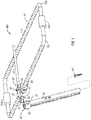
- FIGURE 1 depicts a diagrammatic representation of system 100 usable to adjust the alignment of a spinal column, provide access to damaged or degenerative vertebrae, discs or other spine components and stabilize the spine.
- System 100 may include a support body 10, crossbar 15, support body collar 20, linkage 30 and sleeve collar 40.
- Support body 10 can be used to support one or more extender sleeves 50.
- An extender sleeve 50 is a sleeve that can detachably couple to a bone anchor 60 and provide a working passage from the surface of the patient's body to bone anchor 60 so that tools, closure tops or other components can be guided to the bone anchor.
- Example extender sleeves include, but are not limited to, extender sleeves for the PATHFINDER Pedicle Screw System by ZIMMER SPINE of Minneapolis, MN.
- Support body 10 can be formed as a single piece, or can be formed having members 10a and 10b joined by connectors 12a and 12b. In one embodiment, members 10a and 10b can be coupled together in a manner that allows the width of support body 10 to be adjusted. By way of example, but not limitation, members 10a and 10b can slide relative to each other. Support body 10 may include markings 11, which may be useful for a surgeon to determine a characteristic of the spine, such as the separation between adjacent vertebrae during a distraction procedure. Support body 10 may have a curvature generally parallel to the curvature of a spine or a desired curvature of the spine, can be straight or have other desired shape. Support body 10 may be sized for positioning over a single vertebra or a small incision such as found in minimally invasive surgery (MIS), or may be sized for procedures involving multiple MIS incisions or vertebrae.
- MIS minimally invasive surgery
- System 100 can include body collars 20 for translation of components relative to support body 10.
- Support body collar 20 can be translated along support body 10 parallel to the longitudinal axis of the spine so that sleeve 50 can be placed at the appropriate vertebra.
- support body collar 20 can also be rotated relative to support body 10.
- support body 10 may have a generally circular outer cross-sectional profile and support body collars 20 may have a generally circular inner cross-sectional profile to allow rotation of support body collars 20 relative to support body 10 about an axis. Assuming support body 10 is oriented so that the long portions of members 10a and 10b are parallel to the longitudinal axis of the spine, the axis of rotation of collars 20 will also be parallel to the longitudinal axis of the spine.
- the outer surface of support body 10 and inner surface of support body collars 20 may have complementary angular cross-sections to prevent rotation of support body collars 20.
- Support body collars 20 may include a support body collar locking mechanism to inhibit translational or rotational movement of support body collar 20 relative to support instrument support 10.
- a locking mechanism on support body collar 20 may directly engage support instrument support 10 to inhibit movement.
- the locking mechanism can include a ball or pin in collar 20 that rests in complementary holes/detents in support body 10.
- the locking mechanism can include a set screw that advances in support body collar 20 to bias support body 10 against support body collar 20.
- a surgeon can turn knob 46 to easily advance the set screw.
- a squeeze connection other friction fit can be used.
- other mechanisms known in the art can act to prevent translation and/or rotation of collar 20 relative to support body 10.
- a single locking mechanism or separate locking mechanisms can be used to prevent translation and rotation.
- System 100 may further include crossbar 15 having a length for spanning the width of support instrument support 10.
- crossbar 15 can translate relative to support body collar 20.
- a mechanism used to allow or inhibit movement of crossbar 15 relative to support body collar 20 includes crossbar set screw 16. Advancement of crossbar set screw 16 in support body collar 20 may bias support body collar 20 or support instrument support 10 against crossbar 15 to generate a friction force large enough to inhibit movement of crossbar 15 relative to support body collar 20. Other embodiments can use other locking mechanism to inhibit movement of crossbar 15 relative to support body collar 20.
- crossbar 15 can be coupled to support body collar 20 at each end to keep support body collars 20 on members 10a and 10b laterally aligned. Crossbar 15 may also be used to mount additional surgical tools.
- System 100 may further include linkage 30 slidably and rotatably connected to support body collar 20.
- support body collar 20 can define a passage into which linkage 30 fits.
- Linkage 30 can translate laterally in the passage to adjust the distance of sleeve 50 from support instrument support 10.
- Linkage 30 may be generally straight or may have a bend or curve.
- linkage 30, can rotate about an axis perpendicular to the longitudinal axis of the spine. This rotation can orient the sleeve at an angle relative to the anteriorposterior axis of the body.
- a linkage locking mechanism can be used to selectively inhibit translation and/or rotation of linkage 30.
- a mechanism used to allow or inhibit movement of linkage 30 relative to support body collar 20 is linkage set screw 36. By advancing linkage set screw 36 into threads on support body collar 20, linkage set screw 36 may contact linkage 30. Additional advancement of linkage set screw 36 in support body collar 20 may bias linkage 30 against support body collar 20 to generate a friction force large enough to inhibit movement of linkage 30 relative to support body collar 20.
- Other examples of locking mechanisms can include a ball or pin that rests in a complementary hole/detent in linkage 30, a squeeze connection or other friction fit or other mechanism known in the art that can act to prevent translation and/or rotation of linkage 30.
- a single locking mechanism or separate locking mechanisms can be used to prevent translation and rotation.
- connection 34 between sleeve collar 40 and linkage 30 may provide polyaxial movement to allow the angle of sleeve 50 relative to anteriorposterior axis of the patient to be adjusted.
- connection is a ball and socket type joint.
- Second end 44 of sleeve collar 40 and second end 34 of linkage 30 may be locked using a sleeve collar locking mechanism to inhibit movement of sleeve collar 40 relative to linkage 30.
- a set screw, indent/detent, a squeeze connection or other friction fit or other mechanism known in the art can be used to inhibit relative movement of sleeve collar 40 and linkage 30.
- set screw 46 can be advanced through the side of connection 46 to bias a ball in a ball and socket joint against the surface of the socket, thereby inhibiting movement of sleeve collar 44 relative to linkage 30.
- Sleeve collar 40 can couple to extender sleeve 50.
- Sleeve collar 40 can have an open passage 42 with an inner cross-sectional profile to allow sleeve 50 to translate in sleeve collar 40. Passage 42 can also be shaped so that sleeve 50 can also rotate.
- a sleeve locking mechanisms can securely couple sleeve 50 to inhibit translational and rotational movement of sleeve 50 relative to sleeve collar 40.
- a mechanism for inhibiting movement of sleeve collar relative to sleeve 50 is sleeve collar set screw 46.
- sleeve collar set screw 46 By advancing sleeve collar set screw 46 into threads on sleeve collar 40, sleeve collar set screw 46 may contact sleeve 50. Additional advancement of sleeve collar set screw 46 in sleeve collar 40 may bias sleeve collar 40 against sleeve 50 to generate a friction force large enough to inhibit movement of sleeve 50 relative to sleeve collar 40.
- a screw can engage a hole in sleeve 50 to prevent translation
- a ball or pin can engage a corresponding hole/detent to prevent movement
- sleeve collar 40 can be tightened to hold sleeve 50 or other mechanism used to prevent translation and/or rotation of sleeve 50 relative to sleeve collar 40.
- Sleeve 50 may couple to bone anchor 60 such that bone anchors 60 can be manipulated using sleeve 50.
- Sleeve 50 may be coupled to bone anchor 60 before insertion of bone anchor 60 into the patient or may be coupled after bone anchor 60 has been advanced into a vertebra.
- Sleeve 50 can be used to guide tools and components of a spinal stabilization to the bone anchor 60 for installation of the spinal stabilization system. While only one sleeve is shown in Figure 1 , multiple sleeves 50 can be coupled to support body 10. The sleeves 50 or other components can be manipulated as individuals or as a group.
- sleeve 50 can be coupled to support body 10 so that sleeve 50 can be placed in an appropriate longitudinal and lateral position. Additionally, sleeve 50 can rotate about first axis (e.g., parallel to the longitudinal axis), a second axis (perpendicular to the longitudinal axis) and/or polyaxially to position sleeve 50 in a desired orientation relative to the anteriorposterior axis of the patient.
- first axis e.g., parallel to the longitudinal axis
- second axis perpendicular to the longitudinal axis
- polyaxially to position sleeve 50 in a desired orientation relative to the anteriorposterior axis of the patient.
- This allows a surgeon to place sleeve 50 in a desired longitudinal and lateral position and orientation for a procedure and lock sleeve 50 in that position so that the surgeon's hands are free to manipulate other tools.
- the surgeon can unlock one or more degrees of movement of sleeve 50
- Support body 10 can be helpful in spinal stabilization procedures that involve manipulating the vertebrae.
- a spinal procedure in which a surgical instrument support may be helpful is in the treatment of a burst fracture.
- the spine must be brought into proper alignment. This may involve multiple steps, such as the following: a first step in which adjacent vertebrae are rotated to correct for an abnormal spine curvature, a second step in which the affected vertebra is distracted, and a third step in which adjacent vertebrae are moved closer to the injured vertebra.
- Support body 10 provides a stable platform outside of the patient's body for manipulating extender sleeves 50 during such a procedure.
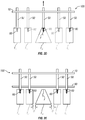
- FIGURES 2A-2D depict a portion of the spine undergoing correction for a burst fracture to vertebra T12.
- FIGURES 2A-2D are discussed in conjunction with FIGURE 1 .
- FIGURE 2A depicts a portion of the spine exhibiting an abnormal spine curvature because of a burst fracture.
- the distance D between the affected vertebra T12 and adjacent vertebrae T11 and L1 may or may not be affected.
- Fluoroscopic imaging or other medical imaging technique can be used to verify the position or angle of a vertebra, the separation or relative positioning between two or more vertebra and the like.
- FIGURE 2B depicts a side view of a portion of the spine with bone anchors 60 installed in the adjacent vertebra T10-T11 and L1-L2.
- Bone anchors 60 are installed using extender sleeves 50.
- Bone anchors 60 and extender sleeves 50 may be advanced into the patient using minimally-invasive surgery (MIS) procedures or other procedures.
- MIS minimally-invasive surgery
- multiple sleeves 50 can be inserted in the patient's body at the same time.
- a parallel row of sleeves may also be used so that there are two (or more) bone anchors are installed in each vertebra.
- Support body 10 can be used to position and orient sleeves 50 during installation of anchors 60. Images of the vertebra can be used to determine the correct position and angle of sleeves 50 relative to the patient's body. The surgeon can lock each sleeve 50 in a desired orientation and lateral/longitudinal position while allowing sleeve 50 to translate in sleeve collar 40 to account for the fact that the depth of sleeve 50 changes as it advances into the body. When a bone anchor 60 is in position, the surgeon can optionally lock all motion of the sleeve 50 relative to support instrument support 10.
- the extender sleeves 50 on either side of the burst fracture can be rotated away from each other as indicated by the arrows.
- the extender sleeves corresponding to vertebrae L1 and L2 can be rotated in a clockwise direction, while the extender sleeves corresponding to vertebrae T10 and T11 can be rotated in a counter clockwise direction.
- each extender sleeve rotates it will move relative to support instrument support 10 in several ways. First, a portion of the sleeve will translate in a longitudinal direction relative to support body 10. Second, the angle of each sleeve 50 will change. Third, the amount each sleeve extends beyond its respective sleeve collar 40 may change.
- the surgeon can configure system 100 to allow select degrees of motion for sleeves 50.
- the surgeon can unlock support body collars 20 associated with vertebrae T10-T11 and L1-L2 so that the support body collars can translate along support instrument support 10, unlock the sleeves 50 so that they can translate in their sleeve collars, and unlock rotation of sleeve collars 40 relative to linkages 30 and/or linkages 30 relative to support body collars 20 to allow the orientation of sleeves 50 to change.
- FIGURE 2C depicts a view of the spine after the curvature has been corrected.
- support body collars 20 can be disengaged from support instrument support 10 so that they are free to translate while movement and rotation in other directions is inhibited.
- Support body collars 20 may then be translated along support instrument support 10 in a desired direction (e.g., as indicated by the arrows). Markings 11 on support instrument support 10 can provide an indication of the distance support body collars 20 are to be moved.
- support body collars 20 may be locked to prevent additional translation.
- FIGURE 2D depicts a view of the spine showing distraction of vertebra T12.
- a bone anchor 60 can be implanted in vertebrae T12 with an extender sleeve 50 coupled to it.
- the orientation and longitudinal/lateral position of the extender sleeve can be locked to prevent undesired movement.
- extender sleeve 50 can be free to translate in the corresponding sleeve collar 40 so that the surgeon can pull extender sleeve 50 to move vertebrae T12.
- the position of extender sleeve 50 relative to sleeve collar 40 can be locked.
- FIGURE 2E depicts a view of the spine after angulation and translation of vertebrae in the spine.
- Rod 80 may be inserted in bone screws 60 to lock the spine in place.
- the spinal stabilization rod 80 can also be coupled to vertebra T12.
- Spinal stabilization rod 80 can be a rigid stabilization rod or can be a dynamic stabilization rod having portions with various degrees of flexibility.
- Spinal stabilization rod 80 can be installed using any suitable procedure known or developed in the art.
- surgical instrument support 10 can be used in any number of procedures in which extender sleeves are used. Multiple surgical instrument supports may be used as needed or desired.
- Components of system 100 can be formed any suitable material(s) including, but not limited to, titanium, titanium alloys, stainless steel, ceramics, and/or polymers. Some components of a spinal stabilization system may be autoclaved and/or chemically sterilized. Components that may not be autoclaved and/or chemically sterilized may be made of sterile materials. Components made of sterile materials may be placed in working relation to other sterile components.
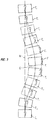
- FIGURE 3 depicts a posterior view of a portion of a spine, showing an abnormal curvature such as scoliosis.
- a spine may have an associated curvature C away from a desired alignment N, and may also be twisted such that the spinous processes have an additional element T.
- support body 10 can be used to aid in adjusting vertebrae individually or in groups to correct the curvature.
- vertebra T8 may be individually rotated into alignment with vertebrae T7 and T9
- vertebrae T7-T9 may be rotated as a group into alignment with vertebrae T6 and T10, and so forth.
- vertebra T4-T12 may be rotated as a group until vertebrae T4 and T12 are in alignment with vertebrae T3 and L1, vertebrae T5-T11 may be further rotated until vertebrae T5 and T11 are in alignment with T4 and T12, and so forth.
- a first surgical instrument support is used in adjusting vertebrae T3-T8 and a second surgical instrument support is used in adjusting vertebrae T9-L1.
Landscapes
- Health & Medical Sciences (AREA)
- Neurology (AREA)
- Orthopedic Medicine & Surgery (AREA)
- Life Sciences & Earth Sciences (AREA)
- Surgery (AREA)
- Heart & Thoracic Surgery (AREA)
- Engineering & Computer Science (AREA)
- Biomedical Technology (AREA)
- Nuclear Medicine, Radiotherapy & Molecular Imaging (AREA)
- Medical Informatics (AREA)
- Molecular Biology (AREA)
- Animal Behavior & Ethology (AREA)
- General Health & Medical Sciences (AREA)
- Public Health (AREA)
- Veterinary Medicine (AREA)
- Surgical Instruments (AREA)
Claims (15)
- System (100) zur Positionierung von Komponenten in der Wirbelsäulenchirurgie, umfassend:einen Träger für ein chirurgisches Instrument mit einem Trägerkörper (10), der ein erstes Element und ein zweites Element mit parallelen Teilen umfasst, die sich in eine erste Richtung erstrecken, wobei das erste Element verschiebbar mit dem zweiten Element verbunden ist;einen ersten Trägerkörperkragen (20), der an dem ersten Element angebracht und entlang dem ersten Element verschoben werden kann;einen Trägerkörperkragen-Verriegelungsmechanismus, die Verschiebung des ersten Trägerkörperkragens (20) selektiv zu hemmen;ein erstes Verbindungsmittel (30), das mit dem ersten Trägerkörperkragen (20) gekoppelt ist, im Verhältnis zu dem ersten Trägerkörperkragen senkrecht zu der ersten Richtung verschiebbar;einen Verbindungsmittelverriegelungsmechanismus, um die Verschiebung dem ersten Verbindungsmittel (30) im Verhältnis zu dem ersten Trägerkörperkragen (20) selektiv zu hemmen;einen ersten Buchsenkragen (40), der mit dem ersten Verbindungsmittel (30) über eine Verbindung verbunden ist, die eine mehrachsige Rotation des ersten Buchsenkragens (40) im Verhältnis zu dem ersten Verbindungsmittel (30) ermöglicht, wobei der erste Buchsenkragen (40) für die Aufnahme einer Extenderbuchse (50) für die Installation von Knochenankern (60) bemessen ist und um es zu ermöglichen, dass sich die Extenderbuchse (50) in dem ersten Buchsenkragen (40) verschiebt;einen Buchsenkragen-Verriegelungsmechanismus, um die Rotation des ersten Buchsenkragens (40) zu hemmen;einen Extenderbuchsen-Verriegelungsmechanismus, um die Verschiebung der Extenderbuchse (50) in dem ersten Buchsenkragen (40) zu hemmen.
- System nach Anspruch 1, ferner umfassend:einen Knochenanker (60); undeine Extenderbuchse (50), die sich durch den ersten Buchsenkragen (40) erstreckt und mit dem Knochenanker (60) gekoppelt ist;wobei der erste Buchsenkragen (40) eine Öffnung mit einer komplementären Form zu der äußeren Form der Extenderbuchse aufweist.
- System nach Anspruch 1, ferner eine Gruppe von Verbindern zur sicheren Verbindung der ersten und zweiten Elemente umfassend.
- System nach Anspruch 1, wobei der Trägerkörperkragen-Verriegelungsmechanismus eine Trägerkörperkragen-Stellschraube umfasst, und wobei der erste Trägerkörperkragen (20) durch den Vorschub der Trägerkörperkragen-Stellschraube in dem ersten Trägerkörperkragen (20) gegen den Trägerkörper (10) vorbelastet wird, um die Bewegung des ersten Trägerkörperkragens (20) im Verhältnis zu dem Rahmen zu hemmen.
- System nach Anspruch 1, wobei das erste Verbindungsmittel (30) im Verhältnis zu dem ersten Trägerkörperkragen (20) um eine Drehachse senkrecht zu der ersten Richtung drehbar ist, und wobei der Verbindungsmittelverriegelungsmechanismus die Rotation des ersten Verbindungsmittels (30) im Verhältnis zu dem ersten Trägerkörperkragen (20) selektiv hemmen kann.
- System nach Anspruch 5, wobei der Verbindungsmittelverriegelungsmechanismus eine Verbindungsmittel-Stellschraube umfasst, und wobei ein Vorschub der Verbindungsmittel-Stellschraube in dem ersten Trägerkörperkragen (20) das erste Verbindungsmittel (30) gegen den Trägerkörperkragen (20) vorbelastet, um die Bewegung des ersten Verbindungsmittels (30) im Verhältnis zu dem ersten Trägerkörperkragen (20) zu hemmen.
- System nach Anspruch 1, wobei der Buchsenverriegelungsmechanismus eine Buchsenstellschraube umfasst, und wobei ein Vorschub der Buchsenstellschraube die Buchse gegen den ersten Buchsenkragen (40) vorbelastet, um die Verschiebung der Buchse in dem ersten Buchsenkragen (40) zu hemmen.
- System nach Anspruch 1, wobei der erste Buchsenkragen (40) durch ein Kugel-Pfannen-Gelenk mit dem ersten Verbindungsmittel (30) verbunden ist.
- System nach Anspruch 8, wobei der Trägerkörperkragen-Verriegelungsmechanismus eine Trägerkörperkragen-Stellschraube umfasst, und wobei ein Vorschub der Trägerkörperkragen-Stellschraube die Kugel gegen eine Oberfläche der Pfanne vorbelastet, um die Rotation des ersten Trägerkörperkragens (20) zu hemmen.
- System nach Anspruch 1, ferner umfassend:eine Gruppe von Trägerkörperkrägen (20), wobei die Gruppe von Trägerkörperkrägen (20) einen ersten Trägerkörperkragen (20) aufweist, und wobei jeder Trägerkörperkragen (20) einen ersten Durchgang mit einem Innenseitenprofil aufweist, das komplementär ist zu einem Außenseitenprofil des Trägerkörpers (10), um eine Verschiebung des Trägerkörperkragens (20) im Verhältnis zu dem Trägerkörper (10) zu ermöglichen;eine Gruppe von Verbindungsmitteln (30), wobei die Gruppe von Verbindungsmitteln (30) das erste Verbindungsmittel (30) aufweist, und wobei jeder Trägerkörperkragen (20) einen zweiten Durchgang mit einem Innenseitenprofil aufweist, das komplementär ist zu einem Außenseitenprofil eines Verbindungsmittels (30) der Gruppe von Verbindungsmitteln (30), um eine Rotation und Verschiebung des Verbindungsmittels (30) im Verhältnis zu dem Trägerkörperkragen (20) zu ermöglichen;eine Gruppe von Querstreben (15), wobei jeder Trägerkörperkragen (20) einen dritten Durchgang mit einem Innenseitenprofil aufweist, das komplementär ist zu einem Außenseitenprofil einer Querstrebe (15) der Gruppe von Querstreben (15), um eine Rotation und Verschiebung der Querstrebe (15) im Verhältnis zu dem Trägerkörperkragen (20) zu ermöglichen, wobei wenigstens eine der Querstreben (15) mit zwei Trägerkörperkrägen (20) gekoppelt ist;eine Gruppe von Buchsenkrägen (40), wobei die Gruppe von Buchsenkrägen (40) den ersten Buchsenkragen (40) aufweist, und wobei jeder Buchsenkragen über eine Verbindung mit einem Verbindungsmittel (30) der Gruppe von Verbindungsmitteln (30) gekoppelt ist, die eine mehrachsige Rotation des Buchsenkragens (40) im Verhältnis zu einem entsprechenden Verbindungsmittel (30) ermöglicht;eine Gruppe von Extenderbuchsen, wobei jeder Buchsenkragen (40) einen Buchsendurchgang mit einer Innenseite aufweist, die komplementär ist zu einem Außenseitenprofil einer Extenderbuchse (50) in der Gruppe von Extenderbuchsen, um eine Verschiebung der Extenderbuchse (50) im Verhältnis zu dem Buchsenkragen (40) zu ermöglichen; undeine Gruppe von Knochenankern, wobei jeder Knochenanker ein Gewindeende zum Vorschub in Knochengewebe aufweist, wobei jede Extenderbuchse (50) mit einem Knochenanker der Gruppe von Knochenankern gekoppelt ist.
- System nach Anspruch 10, ferner umfassend eine Gruppe von Verriegelungsmechanismen, um eine Verschiebung jedes Trägerkörperkragens (20), eine Verschiebung jedes Verbindungsmittels (30) im Verhältnis zu einem entsprechenden Trägerkörperkragen (20), eine Rotation jedes Buchsenkragens (40) im Verhältnis zu dem entsprechenden Verbindungsmittel (30) und eine Verschiebung jeder Buchse in einem entsprechenden Buchsenkragen (40) zu hemmen.
- System nach Anspruch 10, wobei das erste Element und das zweite Element im Verhältnis zueinander lateral verschiebbar sind.
- System nach Anspruch 10, wobei der Eingriff einer oder mehrerer Komponenten der Gruppe von Trägerkörperkrägen (20), der Gruppe von Querstreben (15), der Gruppe von Verbindungsmitteln (30) und der Gruppe von Buchsenkrägen (40) die Bewegung wenigstens eines Teils des Systems hemmt.
- System nach Anspruch 13, wobei
jeder Trägerkörperkragen (20) folgendes umfasst:einen Trägerkörperkragen-Verriegelungsmechanismus, um die Bewegung des Trägerkörperkragens (20) im Verhältnis zu dem Trägerkörper (10) zu hemmen;einen Verriegelungsmechanismus für Verbindungsmittel (30), um die Bewegung eines Verbindungsmittels der Gruppe von Verbindungsmitteln (30) im Verhältnis zu dem Trägerkörperkragen (20) zu hemmen;wobei jeder Buchsenkragen (40) folgendes umfasst:
einen Buchsenverriegelungsmechanismus, um die Bewegung des Buchsenkragens (40) im Verhältnis zu der Buchse zu hemmen; und
wobei jedes Verbindungsmittel (30) folgendes umfasst:
einen Buchsenkragen-Verriegelungsmechanismus, um die Bewegung des Verbindungsmittels (30) im Verhältnis zu dem Buchsenkragen (40) zu hemmen. - System nach Anspruch 14, wobei der Trägerkörperkragen-Verriegelungsmechanismus eine Trägerkörperkragen-Stellschraube umfasst, wobei ein Vorschub der Trägerkörperkragen-Stellschraube in dem Trägerkörperkragen (20) den Trägerkörperkragen (20) gegen den Trägerkörper (10) vorbelastet, um die Bewegung des Trägerkörperkragens (20) im Verhältnis zu dem Trägerkörper (10) zu hemmen; und
wobei der Verriegelungsmechanismus für Verbindungsmittel (30) eine Stellschraube für Verbindungsmittel (30) umfasst, wobei ein Vorschub der Stellschraube für Verbindungsmittel (30) in dem Trägerkörperkragen (20) den Trägerkörperkragen (20) gegen das Verbindungsmittel (30) vorbelastet, um die Bewegung des Verbindungsmittels (30) im Verhältnis zu dem Trägerkörperkragen (20) zu hemmen;
wobei der Buchsenkragen (40) über eine Kugel-Pfannen-Verbindung mit dem Verbindungsmittel (30) gekoppelt ist, und wobei der Verriegelungsmechanismus für einen Buchsenkragen (40) eine Buchsenkragen-Stellschraube umfasst, wobei ein Vorschub der Buchsenkragen-Stellschraube die Kugel gegen eine Oberfläche der Pfanne vorbelastet, um die Bewegung des Buchsenkragens (40) im Verhältnis zu dem Verbindungsmittel zu hemmen; und
wobei der Buchsenverriegelungsmechanismus eine Buchsenstellschraube umfasst, wobei ein Vorschub der Buchsenstellschraube in dem Buchsenkragen (40) die Buchse gegen den Buchsenkragen (40) vorbelastet, um die Bewegung der Buchse im Verhältnis zu dem Buchsenkragen (40) zu hemmen.
Applications Claiming Priority (2)
| Application Number | Priority Date | Filing Date | Title |
|---|---|---|---|
| US12/885,673 US8623022B2 (en) | 2010-09-20 | 2010-09-20 | Surgical instrument support system and method |
| PCT/US2011/049196 WO2012039886A1 (en) | 2010-09-20 | 2011-08-25 | Spinal surgical instrument support system |
Publications (2)
| Publication Number | Publication Date |
|---|---|
| EP2618754A1 EP2618754A1 (de) | 2013-07-31 |
| EP2618754B1 true EP2618754B1 (de) | 2018-06-06 |
Family
ID=44588201
Family Applications (1)
| Application Number | Title | Priority Date | Filing Date |
|---|---|---|---|
| EP11752413.2A Not-in-force EP2618754B1 (de) | 2010-09-20 | 2011-08-25 | Trägersystem für chirurgisches wirbensäuleninstrument |
Country Status (3)
| Country | Link |
|---|---|
| US (1) | US8623022B2 (de) |
| EP (1) | EP2618754B1 (de) |
| WO (1) | WO2012039886A1 (de) |
Families Citing this family (22)
| Publication number | Priority date | Publication date | Assignee | Title |
|---|---|---|---|---|
| WO2012034005A2 (en) * | 2010-09-09 | 2012-03-15 | Synthes Usa, Llc | Vertebral adjustment systems for spine alignment |
| US20140107707A1 (en) * | 2011-02-10 | 2014-04-17 | Robert A. Rovner | Table anchored scoliosis de-rotation system and method |
| US9907582B1 (en) | 2011-04-25 | 2018-03-06 | Nuvasive, Inc. | Minimally invasive spinal fixation system and related methods |
| WO2014018624A1 (en) * | 2012-07-27 | 2014-01-30 | Spinal Usa, Inc. | Minimally invasive devices, systems and methods for treating the spine |
| TWI481382B (zh) * | 2012-08-31 | 2015-04-21 | Univ Nat Cheng Kung | 經皮穿刺輔助裝置及經皮導引組件 |
| US9241742B2 (en) | 2013-03-14 | 2016-01-26 | DePuy Synthes Products, Inc. | Methods and devices for polyaxial screw alignment |
| US9480504B1 (en) | 2013-03-15 | 2016-11-01 | Nuvasive, Inc. | Spinal alignment frame |
| US9402660B2 (en) | 2013-09-05 | 2016-08-02 | Warsaw Orthopedic, Inc. | Surgical instrument and method |
| US10194960B1 (en) | 2015-12-03 | 2019-02-05 | Nuvasive, Inc. | Spinal compression instrument and related methods |
| US10390862B2 (en) | 2016-04-27 | 2019-08-27 | Warsaw Orthopedic, Inc. | Spinal correction system and method |
| USD842479S1 (en) | 2016-04-27 | 2019-03-05 | Warsaw Orthopedic, Inc. | Spinal implant |
| US10194958B2 (en) | 2016-04-27 | 2019-02-05 | Warsaw Othopedic, Inc. | Spinal correction system and method |
| US11051859B2 (en) | 2016-04-27 | 2021-07-06 | Warsaw Orthopedic, Inc. | Spinal correction system and method |
| CN109788975A (zh) | 2016-07-01 | 2019-05-21 | 纽文思公司 | 脊柱损伤矫正和固定 |
| US10543022B2 (en) | 2016-10-11 | 2020-01-28 | Warsaw Orthopedic, Inc. | Spinal implant system and method |
| US10786328B2 (en) * | 2016-10-26 | 2020-09-29 | Thompson Surgical Instruments, Inc. | Adaptor handle for surgical retractor |
| ES2871543T3 (es) * | 2018-01-26 | 2021-10-29 | Aesculap Ag | Instrumento de reposicionamiento espinal y sistema de reposicionamiento espinal |
| US10646261B2 (en) | 2018-07-24 | 2020-05-12 | Warsaw Orthopedic, Inc. | Multi-purpose screwdriver and method of use |
| US11617602B2 (en) | 2020-04-16 | 2023-04-04 | Medtronic, Inc. | Systems, methods of use and surgical instruments employing a secure slide lock to fasten a head |
| US11439442B2 (en) | 2020-04-16 | 2022-09-13 | Warsaw Orthopedic, Inc. | Modular screw system with head locker and derotator |
| US11617603B2 (en) | 2020-12-09 | 2023-04-04 | Warsaw Orthopedic, Inc. | Modular surgical instrument system with ratcheting reduction mechanism |
| US11406431B1 (en) | 2021-05-10 | 2022-08-09 | Warsaw Orthopedic, Inc. | Systems and methods of use and modular instruments with a lateral reducer |
Citations (1)
| Publication number | Priority date | Publication date | Assignee | Title |
|---|---|---|---|---|
| US20040230191A1 (en) * | 2002-11-23 | 2004-11-18 | George Frey | Distraction and retraction system for spinal surgery |
Family Cites Families (27)
| Publication number | Priority date | Publication date | Assignee | Title |
|---|---|---|---|---|
| US4505268A (en) | 1983-02-17 | 1985-03-19 | Vicente Sgandurra | Scoliosis frame |
| US4823781A (en) | 1987-07-02 | 1989-04-25 | Buchanan William J | Method and apparatus for percutaneous fracture reduction and fixation |
| US7060066B2 (en) | 2002-06-28 | 2006-06-13 | Mayo Foundation For Medical Education And Research | Spinal fixation support device and methods of using |
| US20060095035A1 (en) | 2004-11-03 | 2006-05-04 | Jones Robert J | Instruments and methods for reduction of vertebral bodies |
| US9539012B2 (en) | 2002-10-30 | 2017-01-10 | Zimmer Spine, Inc. | Spinal stabilization systems with quick-connect sleeve assemblies for use in surgical procedures |
| ES2629431T3 (es) | 2002-10-30 | 2017-08-09 | Zimmer Spine, Inc. | Sistema de estabilización espinal por inserción |
| US7455685B2 (en) | 2003-09-29 | 2008-11-25 | Warsaw Orthopedic, Inc. | Instruments and methods for securing a connecting element along a bony segment |
| US7465306B2 (en) | 2004-08-13 | 2008-12-16 | Warsaw Orthopedic, Inc. | System and method for positioning a connecting member adjacent the spinal column in minimally invasive procedures |
| US8075591B2 (en) | 2004-11-09 | 2011-12-13 | Depuy Spine, Inc. | Minimally invasive spinal fixation guide systems and methods |
| US7811288B2 (en) | 2004-12-02 | 2010-10-12 | Zimmer Spine, Inc. | Instruments and methods for adjusting separation distance of vertebral bodies with a minimally invasive spinal stabilization procedure |
| US7951175B2 (en) | 2005-03-04 | 2011-05-31 | Depuy Spine, Inc. | Instruments and methods for manipulating a vertebra |
| US7914536B2 (en) | 2005-03-11 | 2011-03-29 | Aesculap Ag | Bone repair device and method |
| US7758617B2 (en) | 2005-04-27 | 2010-07-20 | Globus Medical, Inc. | Percutaneous vertebral stabilization system |
| US8177817B2 (en) | 2005-05-18 | 2012-05-15 | Stryker Spine | System and method for orthopedic implant configuration |
| US20070083210A1 (en) | 2005-09-16 | 2007-04-12 | Zimmer Spine, Inc. | Apparatus and method for minimally invasive spine surgery |
| US7717919B2 (en) | 2005-11-04 | 2010-05-18 | Trans1 Inc. | Application of therapy aligned to an internal target path |
| US7520879B2 (en) | 2006-02-07 | 2009-04-21 | Warsaw Orthopedic, Inc. | Surgical instruments and techniques for percutaneous placement of spinal stabilization elements |
| EP2043528A2 (de) | 2006-06-09 | 2009-04-08 | Zimmer Spine, Inc. | Verfahren und gerät für den zugang zur und/oder die behandlung der wirbelsäule |
| US8834527B2 (en) | 2006-06-16 | 2014-09-16 | Alphatec Spine, Inc. | Systems and methods for manipulating and/or installing a pedicle screw |
| US20080077155A1 (en) | 2006-09-25 | 2008-03-27 | Jennifer Diederich | System and method for displacement of bony structures |
| US9101401B2 (en) | 2006-11-20 | 2015-08-11 | Aesculap Implant Systems, Llc | Bone repair device and method |
| US8679128B2 (en) | 2006-12-07 | 2014-03-25 | Zimmer Spine, Inc. | Apparatus and methods for reduction of vertebral bodies in a spine |
| US7922731B2 (en) | 2006-12-22 | 2011-04-12 | Aesculap Ag | Surgical instrument and osteosynthesis device |
| US20080172062A1 (en) | 2007-01-12 | 2008-07-17 | Depuy Spine, Inc. | Bone anchor manipulation device |
| US8608746B2 (en) | 2008-03-10 | 2013-12-17 | DePuy Synthes Products, LLC | Derotation instrument with reduction functionality |
| WO2009158707A1 (en) | 2008-06-27 | 2009-12-30 | K2M, Inc. | System and method for performing spinal surgery |
| EP2742884B1 (de) | 2008-10-23 | 2018-10-31 | Alphatec Spine, Inc. | Systeme zur Wirbelsäulenfixierung |
-
2010
- 2010-09-20 US US12/885,673 patent/US8623022B2/en active Active
-
2011
- 2011-08-25 WO PCT/US2011/049196 patent/WO2012039886A1/en not_active Ceased
- 2011-08-25 EP EP11752413.2A patent/EP2618754B1/de not_active Not-in-force
Patent Citations (1)
| Publication number | Priority date | Publication date | Assignee | Title |
|---|---|---|---|---|
| US20040230191A1 (en) * | 2002-11-23 | 2004-11-18 | George Frey | Distraction and retraction system for spinal surgery |
Also Published As
| Publication number | Publication date |
|---|---|
| US20120071885A1 (en) | 2012-03-22 |
| EP2618754A1 (de) | 2013-07-31 |
| US8623022B2 (en) | 2014-01-07 |
| WO2012039886A1 (en) | 2012-03-29 |
Similar Documents
| Publication | Publication Date | Title |
|---|---|---|
| EP2618754B1 (de) | Trägersystem für chirurgisches wirbensäuleninstrument | |
| US12185990B2 (en) | Spinal alignment frame | |
| US8747409B2 (en) | Surgical instrument for positioning a spinal rod | |
| US8167908B2 (en) | Polyaxial transverse connector | |
| EP2187825B1 (de) | Wirbelsäulen-vernetzungsgerät für die minimal-invasive chirurgie | |
| US8992536B2 (en) | Coplanar deformity correction system | |
| US9066763B2 (en) | Surgical instrument with integrated reduction and distraction mechanisms | |
| EP3525700B1 (de) | Wirbelsäulenimplantatsystem | |
| EP2240101B1 (de) | Hybrid dynamische stabilisierung | |
| US8591551B2 (en) | Linked spinal stabilization elements for spinal fixation | |
| US20230210508A1 (en) | Surgical system | |
| EP2363086B1 (de) | Transpedikularesreposition Schrauben | |
| US20200022734A1 (en) | Apparatus, system, and method for spinal vertebrae stabilization | |
| Stienen et al. | and Anand Veeravagu, MD |
Legal Events
| Date | Code | Title | Description |
|---|---|---|---|
| PUAI | Public reference made under article 153(3) epc to a published international application that has entered the european phase |
Free format text: ORIGINAL CODE: 0009012 |
|
| 17P | Request for examination filed |
Effective date: 20130416 |
|
| AK | Designated contracting states |
Kind code of ref document: A1 Designated state(s): AL AT BE BG CH CY CZ DE DK EE ES FI FR GB GR HR HU IE IS IT LI LT LU LV MC MK MT NL NO PL PT RO RS SE SI SK SM TR |
|
| DAX | Request for extension of the european patent (deleted) | ||
| GRAP | Despatch of communication of intention to grant a patent |
Free format text: ORIGINAL CODE: EPIDOSNIGR1 |
|
| INTG | Intention to grant announced |
Effective date: 20171215 |
|
| GRAS | Grant fee paid |
Free format text: ORIGINAL CODE: EPIDOSNIGR3 |
|
| GRAA | (expected) grant |
Free format text: ORIGINAL CODE: 0009210 |
|
| AK | Designated contracting states |
Kind code of ref document: B1 Designated state(s): AL AT BE BG CH CY CZ DE DK EE ES FI FR GB GR HR HU IE IS IT LI LT LU LV MC MK MT NL NO PL PT RO RS SE SI SK SM TR |
|
| REG | Reference to a national code |
Ref country code: GB Ref legal event code: FG4D |
|
| REG | Reference to a national code |
Ref country code: CH Ref legal event code: EP Ref country code: AT Ref legal event code: REF Ref document number: 1005189 Country of ref document: AT Kind code of ref document: T Effective date: 20180615 |
|
| REG | Reference to a national code |
Ref country code: IE Ref legal event code: FG4D |
|
| REG | Reference to a national code |
Ref country code: DE Ref legal event code: R096 Ref document number: 602011049048 Country of ref document: DE |
|
| REG | Reference to a national code |
Ref country code: FR Ref legal event code: PLFP Year of fee payment: 8 |
|
| REG | Reference to a national code |
Ref country code: NL Ref legal event code: MP Effective date: 20180606 |
|
| REG | Reference to a national code |
Ref country code: LT Ref legal event code: MG4D |
|
| PG25 | Lapsed in a contracting state [announced via postgrant information from national office to epo] |
Ref country code: ES Free format text: LAPSE BECAUSE OF FAILURE TO SUBMIT A TRANSLATION OF THE DESCRIPTION OR TO PAY THE FEE WITHIN THE PRESCRIBED TIME-LIMIT Effective date: 20180606 Ref country code: LT Free format text: LAPSE BECAUSE OF FAILURE TO SUBMIT A TRANSLATION OF THE DESCRIPTION OR TO PAY THE FEE WITHIN THE PRESCRIBED TIME-LIMIT Effective date: 20180606 Ref country code: CY Free format text: LAPSE BECAUSE OF FAILURE TO SUBMIT A TRANSLATION OF THE DESCRIPTION OR TO PAY THE FEE WITHIN THE PRESCRIBED TIME-LIMIT Effective date: 20180606 Ref country code: FI Free format text: LAPSE BECAUSE OF FAILURE TO SUBMIT A TRANSLATION OF THE DESCRIPTION OR TO PAY THE FEE WITHIN THE PRESCRIBED TIME-LIMIT Effective date: 20180606 Ref country code: NO Free format text: LAPSE BECAUSE OF FAILURE TO SUBMIT A TRANSLATION OF THE DESCRIPTION OR TO PAY THE FEE WITHIN THE PRESCRIBED TIME-LIMIT Effective date: 20180906 Ref country code: BG Free format text: LAPSE BECAUSE OF FAILURE TO SUBMIT A TRANSLATION OF THE DESCRIPTION OR TO PAY THE FEE WITHIN THE PRESCRIBED TIME-LIMIT Effective date: 20180906 Ref country code: SE Free format text: LAPSE BECAUSE OF FAILURE TO SUBMIT A TRANSLATION OF THE DESCRIPTION OR TO PAY THE FEE WITHIN THE PRESCRIBED TIME-LIMIT Effective date: 20180606 |
|
| PG25 | Lapsed in a contracting state [announced via postgrant information from national office to epo] |
Ref country code: GR Free format text: LAPSE BECAUSE OF FAILURE TO SUBMIT A TRANSLATION OF THE DESCRIPTION OR TO PAY THE FEE WITHIN THE PRESCRIBED TIME-LIMIT Effective date: 20180907 Ref country code: RS Free format text: LAPSE BECAUSE OF FAILURE TO SUBMIT A TRANSLATION OF THE DESCRIPTION OR TO PAY THE FEE WITHIN THE PRESCRIBED TIME-LIMIT Effective date: 20180606 Ref country code: LV Free format text: LAPSE BECAUSE OF FAILURE TO SUBMIT A TRANSLATION OF THE DESCRIPTION OR TO PAY THE FEE WITHIN THE PRESCRIBED TIME-LIMIT Effective date: 20180606 Ref country code: HR Free format text: LAPSE BECAUSE OF FAILURE TO SUBMIT A TRANSLATION OF THE DESCRIPTION OR TO PAY THE FEE WITHIN THE PRESCRIBED TIME-LIMIT Effective date: 20180606 |
|
| REG | Reference to a national code |
Ref country code: AT Ref legal event code: MK05 Ref document number: 1005189 Country of ref document: AT Kind code of ref document: T Effective date: 20180606 |
|
| PG25 | Lapsed in a contracting state [announced via postgrant information from national office to epo] |
Ref country code: NL Free format text: LAPSE BECAUSE OF FAILURE TO SUBMIT A TRANSLATION OF THE DESCRIPTION OR TO PAY THE FEE WITHIN THE PRESCRIBED TIME-LIMIT Effective date: 20180606 |
|
| PG25 | Lapsed in a contracting state [announced via postgrant information from national office to epo] |
Ref country code: RO Free format text: LAPSE BECAUSE OF FAILURE TO SUBMIT A TRANSLATION OF THE DESCRIPTION OR TO PAY THE FEE WITHIN THE PRESCRIBED TIME-LIMIT Effective date: 20180606 Ref country code: CZ Free format text: LAPSE BECAUSE OF FAILURE TO SUBMIT A TRANSLATION OF THE DESCRIPTION OR TO PAY THE FEE WITHIN THE PRESCRIBED TIME-LIMIT Effective date: 20180606 Ref country code: SK Free format text: LAPSE BECAUSE OF FAILURE TO SUBMIT A TRANSLATION OF THE DESCRIPTION OR TO PAY THE FEE WITHIN THE PRESCRIBED TIME-LIMIT Effective date: 20180606 Ref country code: IS Free format text: LAPSE BECAUSE OF FAILURE TO SUBMIT A TRANSLATION OF THE DESCRIPTION OR TO PAY THE FEE WITHIN THE PRESCRIBED TIME-LIMIT Effective date: 20181006 Ref country code: PL Free format text: LAPSE BECAUSE OF FAILURE TO SUBMIT A TRANSLATION OF THE DESCRIPTION OR TO PAY THE FEE WITHIN THE PRESCRIBED TIME-LIMIT Effective date: 20180606 Ref country code: AT Free format text: LAPSE BECAUSE OF FAILURE TO SUBMIT A TRANSLATION OF THE DESCRIPTION OR TO PAY THE FEE WITHIN THE PRESCRIBED TIME-LIMIT Effective date: 20180606 Ref country code: EE Free format text: LAPSE BECAUSE OF FAILURE TO SUBMIT A TRANSLATION OF THE DESCRIPTION OR TO PAY THE FEE WITHIN THE PRESCRIBED TIME-LIMIT Effective date: 20180606 |
|
| PG25 | Lapsed in a contracting state [announced via postgrant information from national office to epo] |
Ref country code: SM Free format text: LAPSE BECAUSE OF FAILURE TO SUBMIT A TRANSLATION OF THE DESCRIPTION OR TO PAY THE FEE WITHIN THE PRESCRIBED TIME-LIMIT Effective date: 20180606 Ref country code: IT Free format text: LAPSE BECAUSE OF FAILURE TO SUBMIT A TRANSLATION OF THE DESCRIPTION OR TO PAY THE FEE WITHIN THE PRESCRIBED TIME-LIMIT Effective date: 20180606 |
|
| REG | Reference to a national code |
Ref country code: DE Ref legal event code: R097 Ref document number: 602011049048 Country of ref document: DE |
|
| PG25 | Lapsed in a contracting state [announced via postgrant information from national office to epo] |
Ref country code: MC Free format text: LAPSE BECAUSE OF FAILURE TO SUBMIT A TRANSLATION OF THE DESCRIPTION OR TO PAY THE FEE WITHIN THE PRESCRIBED TIME-LIMIT Effective date: 20180606 |
|
| REG | Reference to a national code |
Ref country code: CH Ref legal event code: PL |
|
| PLBE | No opposition filed within time limit |
Free format text: ORIGINAL CODE: 0009261 |
|
| STAA | Information on the status of an ep patent application or granted ep patent |
Free format text: STATUS: NO OPPOSITION FILED WITHIN TIME LIMIT |
|
| PG25 | Lapsed in a contracting state [announced via postgrant information from national office to epo] |
Ref country code: CH Free format text: LAPSE BECAUSE OF NON-PAYMENT OF DUE FEES Effective date: 20180831 Ref country code: LI Free format text: LAPSE BECAUSE OF NON-PAYMENT OF DUE FEES Effective date: 20180831 Ref country code: LU Free format text: LAPSE BECAUSE OF NON-PAYMENT OF DUE FEES Effective date: 20180825 |
|
| REG | Reference to a national code |
Ref country code: BE Ref legal event code: MM Effective date: 20180831 |
|
| 26N | No opposition filed |
Effective date: 20190307 |
|
| PG25 | Lapsed in a contracting state [announced via postgrant information from national office to epo] |
Ref country code: SI Free format text: LAPSE BECAUSE OF FAILURE TO SUBMIT A TRANSLATION OF THE DESCRIPTION OR TO PAY THE FEE WITHIN THE PRESCRIBED TIME-LIMIT Effective date: 20180606 Ref country code: DK Free format text: LAPSE BECAUSE OF FAILURE TO SUBMIT A TRANSLATION OF THE DESCRIPTION OR TO PAY THE FEE WITHIN THE PRESCRIBED TIME-LIMIT Effective date: 20180606 |
|
| PG25 | Lapsed in a contracting state [announced via postgrant information from national office to epo] |
Ref country code: BE Free format text: LAPSE BECAUSE OF NON-PAYMENT OF DUE FEES Effective date: 20180831 |
|
| PG25 | Lapsed in a contracting state [announced via postgrant information from national office to epo] |
Ref country code: AL Free format text: LAPSE BECAUSE OF FAILURE TO SUBMIT A TRANSLATION OF THE DESCRIPTION OR TO PAY THE FEE WITHIN THE PRESCRIBED TIME-LIMIT Effective date: 20180606 |
|
| PG25 | Lapsed in a contracting state [announced via postgrant information from national office to epo] |
Ref country code: MT Free format text: LAPSE BECAUSE OF NON-PAYMENT OF DUE FEES Effective date: 20180825 |
|
| PG25 | Lapsed in a contracting state [announced via postgrant information from national office to epo] |
Ref country code: TR Free format text: LAPSE BECAUSE OF FAILURE TO SUBMIT A TRANSLATION OF THE DESCRIPTION OR TO PAY THE FEE WITHIN THE PRESCRIBED TIME-LIMIT Effective date: 20180606 |
|
| PG25 | Lapsed in a contracting state [announced via postgrant information from national office to epo] |
Ref country code: PT Free format text: LAPSE BECAUSE OF FAILURE TO SUBMIT A TRANSLATION OF THE DESCRIPTION OR TO PAY THE FEE WITHIN THE PRESCRIBED TIME-LIMIT Effective date: 20180606 Ref country code: HU Free format text: LAPSE BECAUSE OF FAILURE TO SUBMIT A TRANSLATION OF THE DESCRIPTION OR TO PAY THE FEE WITHIN THE PRESCRIBED TIME-LIMIT; INVALID AB INITIO Effective date: 20110825 |
|
| PG25 | Lapsed in a contracting state [announced via postgrant information from national office to epo] |
Ref country code: MK Free format text: LAPSE BECAUSE OF NON-PAYMENT OF DUE FEES Effective date: 20180606 Ref country code: IE Free format text: LAPSE BECAUSE OF NON-PAYMENT OF DUE FEES Effective date: 20180825 |
|
| REG | Reference to a national code |
Ref country code: DE Ref legal event code: R082 Ref document number: 602011049048 Country of ref document: DE Representative=s name: VENNER SHIPLEY GERMANY LLP, DE Ref country code: DE Ref legal event code: R082 Ref document number: 602011049048 Country of ref document: DE Representative=s name: VENNER SHIPLEY LLP, DE |
|
| PGFP | Annual fee paid to national office [announced via postgrant information from national office to epo] |
Ref country code: FR Payment date: 20200715 Year of fee payment: 10 |
|
| PGFP | Annual fee paid to national office [announced via postgrant information from national office to epo] |
Ref country code: GB Payment date: 20210715 Year of fee payment: 11 |
|
| PG25 | Lapsed in a contracting state [announced via postgrant information from national office to epo] |
Ref country code: FR Free format text: LAPSE BECAUSE OF NON-PAYMENT OF DUE FEES Effective date: 20210831 |
|
| PGFP | Annual fee paid to national office [announced via postgrant information from national office to epo] |
Ref country code: DE Payment date: 20220621 Year of fee payment: 12 |
|
| GBPC | Gb: european patent ceased through non-payment of renewal fee |
Effective date: 20220825 |
|
| PG25 | Lapsed in a contracting state [announced via postgrant information from national office to epo] |
Ref country code: GB Free format text: LAPSE BECAUSE OF NON-PAYMENT OF DUE FEES Effective date: 20220825 |
|
| REG | Reference to a national code |
Ref country code: DE Ref legal event code: R119 Ref document number: 602011049048 Country of ref document: DE |
|
| PG25 | Lapsed in a contracting state [announced via postgrant information from national office to epo] |
Ref country code: DE Free format text: LAPSE BECAUSE OF NON-PAYMENT OF DUE FEES Effective date: 20240301 |