EP2620186A1 - Appareil d'inhalation - Google Patents
Appareil d'inhalation Download PDFInfo
- Publication number
- EP2620186A1 EP2620186A1 EP12152281.7A EP12152281A EP2620186A1 EP 2620186 A1 EP2620186 A1 EP 2620186A1 EP 12152281 A EP12152281 A EP 12152281A EP 2620186 A1 EP2620186 A1 EP 2620186A1
- Authority
- EP
- European Patent Office
- Prior art keywords
- section
- inhalation device
- outer part
- particular according
- inhalation
- Prior art date
- Legal status (The legal status is an assumption and is not a legal conclusion. Google has not performed a legal analysis and makes no representation as to the accuracy of the status listed.)
- Withdrawn
Links
- XLYOFNOQVPJJNP-UHFFFAOYSA-N water Substances O XLYOFNOQVPJJNP-UHFFFAOYSA-N 0.000 claims description 21
- 230000029058 respiratory gaseous exchange Effects 0.000 claims description 13
- 230000008859 change Effects 0.000 claims description 10
- 230000000694 effects Effects 0.000 claims description 7
- 239000011343 solid material Substances 0.000 claims description 5
- 238000011144 upstream manufacturing Methods 0.000 claims description 3
- 238000001914 filtration Methods 0.000 claims description 2
- 239000007921 spray Substances 0.000 claims description 2
- 239000003570 air Substances 0.000 description 37
- CURLTUGMZLYLDI-UHFFFAOYSA-N Carbon dioxide Chemical compound O=C=O CURLTUGMZLYLDI-UHFFFAOYSA-N 0.000 description 26
- 229910002092 carbon dioxide Inorganic materials 0.000 description 13
- 239000001569 carbon dioxide Substances 0.000 description 13
- QVGXLLKOCUKJST-UHFFFAOYSA-N atomic oxygen Chemical compound [O] QVGXLLKOCUKJST-UHFFFAOYSA-N 0.000 description 7
- 239000003795 chemical substances by application Substances 0.000 description 7
- 229910052760 oxygen Inorganic materials 0.000 description 7
- 239000001301 oxygen Substances 0.000 description 7
- 239000011324 bead Substances 0.000 description 6
- 206010021143 Hypoxia Diseases 0.000 description 5
- 230000007704 transition Effects 0.000 description 5
- 230000001146 hypoxic effect Effects 0.000 description 4
- 230000033764 rhythmic process Effects 0.000 description 4
- 206010020591 Hypercapnia Diseases 0.000 description 3
- 230000002349 favourable effect Effects 0.000 description 3
- 239000012530 fluid Substances 0.000 description 3
- 239000002245 particle Substances 0.000 description 3
- 239000000243 solution Substances 0.000 description 3
- 230000001154 acute effect Effects 0.000 description 2
- 230000015572 biosynthetic process Effects 0.000 description 2
- 238000006073 displacement reaction Methods 0.000 description 2
- 239000008187 granular material Substances 0.000 description 2
- 238000002347 injection Methods 0.000 description 2
- 239000007924 injection Substances 0.000 description 2
- 230000009467 reduction Effects 0.000 description 2
- 230000000241 respiratory effect Effects 0.000 description 2
- 238000004088 simulation Methods 0.000 description 2
- HUAUNKAZQWMVFY-UHFFFAOYSA-M sodium;oxocalcium;hydroxide Chemical compound [OH-].[Na+].[Ca]=O HUAUNKAZQWMVFY-UHFFFAOYSA-M 0.000 description 2
- 239000007787 solid Substances 0.000 description 2
- 238000009423 ventilation Methods 0.000 description 2
- TVEXGJYMHHTVKP-UHFFFAOYSA-N 6-oxabicyclo[3.2.1]oct-3-en-7-one Chemical compound C1C2C(=O)OC1C=CC2 TVEXGJYMHHTVKP-UHFFFAOYSA-N 0.000 description 1
- OKTJSMMVPCPJKN-UHFFFAOYSA-N Carbon Chemical compound [C] OKTJSMMVPCPJKN-UHFFFAOYSA-N 0.000 description 1
- 230000006978 adaptation Effects 0.000 description 1
- 239000012080 ambient air Substances 0.000 description 1
- 229910052799 carbon Inorganic materials 0.000 description 1
- 238000011109 contamination Methods 0.000 description 1
- 230000007423 decrease Effects 0.000 description 1
- 210000003743 erythrocyte Anatomy 0.000 description 1
- 230000010437 erythropoiesis Effects 0.000 description 1
- 239000007789 gas Substances 0.000 description 1
- 230000007954 hypoxia Effects 0.000 description 1
- 238000009434 installation Methods 0.000 description 1
- 230000003993 interaction Effects 0.000 description 1
- 239000007788 liquid Substances 0.000 description 1
- 230000014759 maintenance of location Effects 0.000 description 1
- 238000004519 manufacturing process Methods 0.000 description 1
- 238000000034 method Methods 0.000 description 1
- 239000000203 mixture Substances 0.000 description 1
- 210000003205 muscle Anatomy 0.000 description 1
- 230000002093 peripheral effect Effects 0.000 description 1
- 230000008569 process Effects 0.000 description 1
- 150000003839 salts Chemical class 0.000 description 1
- 239000002689 soil Substances 0.000 description 1
- 239000013589 supplement Substances 0.000 description 1
Images


Classifications
-
- A—HUMAN NECESSITIES
- A63—SPORTS; GAMES; AMUSEMENTS
- A63B—APPARATUS FOR PHYSICAL TRAINING, GYMNASTICS, SWIMMING, CLIMBING, OR FENCING; BALL GAMES; TRAINING EQUIPMENT
- A63B23/00—Exercising apparatus specially adapted for particular parts of the body
- A63B23/18—Exercising apparatus specially adapted for particular parts of the body for improving respiratory function
-
- A—HUMAN NECESSITIES
- A63—SPORTS; GAMES; AMUSEMENTS
- A63B—APPARATUS FOR PHYSICAL TRAINING, GYMNASTICS, SWIMMING, CLIMBING, OR FENCING; BALL GAMES; TRAINING EQUIPMENT
- A63B21/00—Exercising apparatus for developing or strengthening the muscles or joints of the body by working against a counterforce, with or without measuring devices
- A63B21/00047—Exercising devices not moving during use
-
- A—HUMAN NECESSITIES
- A63—SPORTS; GAMES; AMUSEMENTS
- A63B—APPARATUS FOR PHYSICAL TRAINING, GYMNASTICS, SWIMMING, CLIMBING, OR FENCING; BALL GAMES; TRAINING EQUIPMENT
- A63B21/00—Exercising apparatus for developing or strengthening the muscles or joints of the body by working against a counterforce, with or without measuring devices
- A63B21/008—Exercising apparatus for developing or strengthening the muscles or joints of the body by working against a counterforce, with or without measuring devices using hydraulic or pneumatic force-resisters
-
- A—HUMAN NECESSITIES
- A63—SPORTS; GAMES; AMUSEMENTS
- A63B—APPARATUS FOR PHYSICAL TRAINING, GYMNASTICS, SWIMMING, CLIMBING, OR FENCING; BALL GAMES; TRAINING EQUIPMENT
- A63B2213/00—Exercising combined with therapy
- A63B2213/005—Exercising combined with therapy with respiratory gas delivering means, e.g. O2
- A63B2213/006—Exercising combined with therapy with respiratory gas delivering means, e.g. O2 under hypoxy conditions, i.e. oxygen supply subnormal
Definitions
- the invention relates to an inhalation device, in particular for training the breathing, with a filter area through which inhaled air is sucked, and a line section downstream of the filter area during inhalation.
- Inhalation devices of the type in question are known. These are used in particular for respiratory training, in particular for simulating altitude training.
- the partial pressure of oxygen decreases linearly with atmospheric pressure as altitude increases, so that one cubic meter of breathing air at altitude contains less oxygen than at sea level.
- an adaptation of the body to the altitude-related hypoxia occurs primarily through increased production of red blood cells (erythropoiesis).
- the capacity of oxygen uptake and transport is thereby increased.
- a hypoxic gas mixture is generated, correspondingly further an artificial reduction of the oxygen content in the breathing air.
- Such inhalers act according to a hypoxic and / or hypercapnic effect.
- a line section downstream of the filter area during inhalation or upstream of the filter area in the course of exhaling is referred to as an alveolar dead space.
- the object of the invention is to provide a conveniently adaptable inhalation device.
- the invention also has the task of an advantageously constructed inhalation device, in particular with regard to manufacturability indicate and / or specify an inhalation device which is advantageous in terms of flow and / or to provide inhalation device, which is also adaptable in another way favorable to the needs of a user.
- an inhalation device in which it is arranged that the volume of the line downstream of the filter area can be changed in its volume.
- an enlargement or reduction of the alveolar dead space is made possible, so as to create a simulation of the oxygen supply at different height conditions using the same inhalation device.
- the change in volume of the line section can be carried out by the user or by a person instructing the user of the inhalation device, more preferably without tools.
- Markers or the like which indicate the respective volume of the line section or the simulated height are furthermore preferably provided on the inhalation device and / or on parts or sections of the inhalation device.
- the inhalation device has a variable volume of 200 to 1200 cm 3 , further example. 300 to 1000 cm 3 or 500 to 800 cm 3 or 400 to 1100 cm 3 .
- a further possible solution of the problem is given according to a further inventive idea in an inhalation device, in which a formed from a solid or a solid bed CO 2 removal agent is arranged leaving a free flow section.
- a cross-section transverse to the flow direction of the inhaled or exhaled air is thus given a first region which is occupied by the carbon dioxide removal agent, but also can be traversed by the air is, and another, second area, which is not occupied by the carbon dioxide removal agent but can also be traversed by the air.
- air inlet or air outlet openings are variable in their effective opening cross-section.
- the breathing resistance can be additionally influenced. This also by the user himself, possibly in the course of use. But it can also be provided in each case a fixed setting that is not changeable by a user.
- the line section is composed of a first, invariable section, which is initially flowed through with respect to the inhaled air, and an adjoining second, changeable section.
- first, invariable section which is initially flowed through with respect to the inhaled air
- second, changeable section can be individual, composable subsections, and also subsections that are captively connected to one another.
- the change in volume preferably takes place by means of the second, variable partial section of the line section, which is further preferably variable with regard to its position and / or with respect to its volume relative to the first unchangeable, more preferably at least not operationally displaceable partial section.
- a connecting section leading to an oral and / or nasal adapter wherein the second, variable partial section is arranged in front of the connecting section when inhaled in the direction of flow, further correspondingly preferably in the course of exhalation in the flow direction behind the connecting section.
- the connecting section is a hose-like, in particular flexible hose-like connecting section in order to offer a favorable handling of the inhalation device.
- an oral adapter When an oral adapter is arranged, it can be designed in the form of a mouthpiece which can be enclosed by the lips.
- a nose adapter in the form of a mask which can be put over the mouth or the nose, more preferably in the form of a mask covering both the mouth and the nose.
- the first and / or second subsection - preferably both - have a larger diameter than the connecting section, so more preferably a diameter of three to twenty times, further a seven to twelve times, such as in particular a ten- suen of the diameter of the mouth and / or nose adapter leading connecting portion corresponds (each preferably based on the free, permeable inside diameter of the sections or the connecting portion).
- the second section can be displaced relative to the first, unchangeable section, for example telescopically displaceable, so that a volume change of the line section as a whole can be achieved by telescoping or pulling apart the two sections. This can be achieved by approximately linear displacement.
- the second section is formed as a replaceable pipe section, this further preferably in total rotationally symmetrical configuration of the inhaler, in particular the line section.
- the second section is replaced.
- further second sections can be assigned, so that they define the sum of the volume of the line section. It is such a modular design given to handle-friendly and easy volume adjustment of the line section to be simulated height conditions.
- the connecting portion to the mouth and / or nose adapter closes in a further preferred embodiment of a cover part, enforcing this accordingly, more preferably in particular in rotationally symmetrical configuration of the inhalation device this centrally enforcing.
- the cover part is preferably screw-connected or clip-connected to the second section, so fitting without tools by the user or removable to the cover-like closure of the second section or the entire line section or to expose the same.
- the filter area can be designed differently.
- the filter region is formed by a fluid, in particular water. It is used in particular for the removal or retention of suspended particles in the air, in particular with respect to an inhalation. It also serves to easily adjust a breathing resistance.
- This filter region is further preferably formed in the intermediate space of an outer part surrounding the first portion and the first portion, wherein more preferably, the outer part and the first portion are each pot-shaped, wherein the outer part, as it were, in particular a diameter enlarged above also preferably formed in vertical extension enlarged planter.
- the hereby adjusting, preferably circumferential gap, more particularly also the resulting between the bottoms of the first section and outer part gap is used in a preferred embodiment, both for the formation of the filter area and as a flow area both in the course of inhalation and in the course of exhalation.
- air inlet or air outlet openings are furthermore preferably formed, which are furthermore preferably arranged correspondingly in the course of the exhalation downstream of the filter area in the flow direction, further in the course of inspiration in the flow direction in front of the filter area.
- the openings are further preferably provided on the wall side of the outer part, in particular according to training the same as, for example, window-like openings.
- the air inlet or air outlet openings are arranged on the end side of the first section, correspondingly more preferably on the end side of the adjoining intermediate space.
- a distance considered in the flow direction preferably at least approximately vertical distance between the filter region and the openings, is achieved in the handling position.
- the air inlet or air outlet openings further provided in particular according to the above-described arrangement in a handling-technically favorable area, which are not covered in particular by the hand holding the inhaler, in particular when properly handled.
- Another advantageous embodiment is that in which the air inlet or air outlet openings over the entire Scope of the outer part distributed, preferably evenly distributed or provided throughout.
- the filter region is further preferably associated with an inflow-side end of the first subsection, further associated with a preferably pot-shaped configuration of the first subsection associated with the bottom region of the pot.
- the air inlet or air outlet openings are assigned to the pot edge of the first section in the over-pot-like outer part. This results in a further preferred embodiment between the outer part and the first portion a vertical cross-section U-shaped gap, this more preferably under concentric arrangement of the outer part and the first section.
- the filter effect is achieved by filled into the space water. Accordingly, the water resistance during inhalation and exhalation can be dosed via the level. As a result, an economization of breathing and training of the ventilation muscles can be achieved.
- in particular of the pot-like outer part of the water level can be read from the outside; correspondingly easy for the user to dose.
- the water can be fed, in particular depending on the desired exercise intensity, additional binding salts.
- the air-flow transition from the first, unchangeable subsection to the intermediate space formed between the first subsection and the outer part is given in a preferred embodiment by through openings provided in the bottom of the first subsection associated with the interspace.
- the bottom of the pot of the first section is sieve-like provided with passage openings, wherein more preferably the filling level of the filter-acting water is selected so that the Water engages into the bottom of the pot portion of the first section, so that accordingly the filter area is provided in the transition region from the first section to the leading to the inlet and outlet openings gap, while avoiding an air flow short circuit between the first section and the gap.
- the inhaled and exhaled air is correspondingly forcibly guided through the filter area, more preferably through the water reservoir with appropriate filtering or binding of carbon dioxide.
- the filling level of the water is preferably 0.5 to 5 cm, this with a further preferred filling quantity of 20 to 100 ml, for example 40, 65 or 80 ml.
- the second, variable, possibly interchangeable subsection is connected in one embodiment to change the line section volume or to change the alveolar dead space with the first, unchangeable section.
- this releasable connection between the second section and the outer part is provided.
- a trained example as a grille splash guard whose passage openings are selected in cross-section so that entrained water droplets can be safely restrained, but in particular in the course of inhalation the airflow passing through the splash guard opposes no or no significant influence resistance.
- a splash guard is also provided with respect to an exhalation upstream of the air outlet openings, so as to be in the course of exhaling possibly entrained water particles to prevent it from escaping from the inhaler through the air vents.
- a receptacle or holder for a timer is furthermore preferably provided on the device, in particular in the region of the outer wall of the outer part. He can be designed as a rhythm generator. The rhythm can be specified visually and / or acoustically.
- a filter area for, in particular, CO 2 removal can also be provided as a supplement or alternatively to the named filter area.
- this solid material is annular, leaving an inner free cross section.
- Both the filled by solid material, preferably outer, section of the cross section perpendicular to the flow direction during inhalation or exhalation can be flowed through as well as the free cross section.
- a diameter dimension of the inner free cross section corresponds to 1/3 to 4/5 of the diameter dimension of the flow-through cross-section as a whole.
- area ratio these details related to a circular cross-section also have significance for designs deviating from the circular cross-section. Since, moreover, preferably said region is conical, more preferably widening toward the mouthpiece, this ratio can also vary over the height.
- the above-mentioned configuration is given over a portion whose height dimension is 1/4 to 2 times that of the above Diameter measure of the permeable area overall corresponds.
- the air inlet and outlet openings are formed in a horizontal section.
- the horizontal section may be a circular ring section, which leads to a step-like taper of the inhalation device in the region of the inlet and outlet openings.
- An adjustment for the air inlet and outlet openings may be achieved, for example, that groove-like, in the circumferential direction preferably of the inhalation device extending openings are provided, which are closed by a slide member to varying degrees.
- an adjusting ring can be provided. The adjustability can be provided simply vorappelbar from the outside.
- the CO 2 removal agent is furthermore preferably provided above, viewed in the air inflow direction, of the liquid or water filter region. More preferably also above a splash guard. In addition, preferably in an (upper) second or further subsection of the inhalation device.
- the ranges or value ranges or multiple ranges given above and below also include all intermediate values, in particular in 1/10 increments of the respective dimension, if necessary also dimensionless, ie, for example, 1/10 (the length or the diameter etc.) on the one hand to delimit the said range limits from below and / or above, alternatively or additionally, but also with regard to the disclosure of one or more singular values from the respectively specified range.
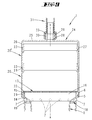
- An inhalation device 1 is shown and described, in particular for exercising respiration, more particularly for producing a hypoxic and hypercapnic effect.
- the inhalation device 1 has an overall pot-like design.
- a pot-shaped or vessel-like outer part 2 is provided.
- the outer part 2 of the illustrated embodiment in this case has a vertical height h, which corresponds to about 1.3 times the average free inner diameter d of the outer part 2.
- the circumferential outer sub-wall 3 extends from the outer-part base 4 in a conically widening manner, including an acute angle to a vertical plane of 1 ° to 3 °.
- Both the outer part wall 3 and the surface configured and aligned transversely to the vertical axis x outer part base 4 are continuously closed designed.
- the outer part bottom 4 is suitable for placing the inhalation device 1 on a surface over it.
- the outer part wall 3 is penetrated by Heileinlass- or air outlet 7. These are realized in the illustrated embodiment as bores, this more preferably with an opening diameter of 8 mm.
- the air inlet or air outlet openings 7 are arranged uniformly spaced from one another over the circumference of the outer part 2.
- first section 8 of a line section 9 is added.
- This inner vessel-like first section 8 extends concentrically with the outer part 2, leaving one in a vertical section according to FIG FIG. 6
- the Operaabiteswandung 11 extends with respect to a vertical section parallel to the outer part wall 3, this further with appropriate spacing, which distance a preferably one-eighth to one-tenth of the mean inner diameter dimension of the outer part 2 corresponds, resulting in a further average Inner diameter d ', which corresponds to about 7/8 to 9/10 of the average outer diameter inside diameter d.
- the bottom 12 of the section 1 is distanced by the distance a to the facing surface of the outer part bottom 4.
- the bottom 12 has bore-like passage openings 13, in each case preferably with a diameter of 1 mm to 3 mm.
- the passage openings 13 are here approximately uniformly distributed over the floor 12 evenly distributed.
- the collar 15 closes in the region of its free end approximately with the free end of the outer edge part 5 from.
- a splash guard 17 which covers the vertically upward-pointing partial section opening 16 is also provided. This is designed like a grid and extends within a transverse to the vertical axis x directed plane.
- the splash guard 17 is in the illustrated embodiment on the free edge of the partial section side collar 15.
- annular splash guard 18 is arranged below the air inlet or air outlet openings 7, the intermediate space 10 crossing, here lies on a radially inwardly retracted support portion 19 of the outer part wall 3.
- the splash guard 17 extends from the radially inner side of the outer part wall 3 to the radially outer side of the
- Another component of the inhalation device 1 is a second, variable partial section 20, which forms the line section 9 together with the first partial section 8 arranged in the outer part 2.
- This second section 20 is generally substantially tubular, with an inner diameter d ", the exceeds the inner diameter of the first section 8 in the region of the collar 15 by about twice the wall thickness.
- the second portion 20 is releasably secured to the outer part 2, this with radial overreach of the vertically lower portion of the second portion 20 via the outer edge part 5.
- the corresponding portion of the second portion 20 is provided for receiving the outer edge of the annular edge bead 6 with a corresponding circumferential groove 21 ,
- the second section 20 is clipped on the outer part 2 according to this embodiment.
- the second section 20 is supported via an inwardly directed radial projection 22 on the associated end face of the outer part edge 5, this rand wornem, encircling encroachment of the spray guard provided here 17.
- the latter and the first section 8 are on the radial projection 22nd secured against displacement in the extension direction of the vertical axis x.
- annular bead 23 which surrounds the annular bead 6 of the outer part 2, is formed circumferentially on the outside of the wall.
- the second section 20 and thus the entire line section 9 is covered by a cover part 24.
- This first has a substantially parallel to the outer part bottom 4 extending ceiling 25, which merges peripherally edge side in a tube-section-shaped cover wall 26.
- the latter is directed in assignment position down in the direction of the outer part bottom 4, so that overall represents a pot-like configuration of the cover member 24 in overhead position.
- the cover wall 26 is adapted in terms of its inner diameter adapted to the outer diameter of the reduced diameter, the annular bead 23 supporting portion of the second section 20, wherein radially inward around corresponding to the interaction with the annular bead 23, a circumferential groove 27 is provided. Also in this regard, a determination of the cover part 24 is achieved according to verclipsung on the second portion 20, which can be canceled by the user without tools.
- a through-flow opening 28 is provided in the middle of the ceiling 25, centrally receiving the vertical axis x.
- This has a circular-disk-shaped cross-section and is on the upper side, that is, the cover wall 26 facing away surrounded by a circular cylindrical connection portion 29.
- the latter has a male thread 30 on the outer wall side.
- a closure cap (not shown) can be screwed onto the connection section 29.
- connection section 31 is assigned to the connection section 29.
- This is preferably a flexible, tube-like section which, facing away from the connection section 29, carries an oral and / or nasal adapter 32.
- the connecting portion 31 has an inner diameter d '", which preferably corresponds to 0.1 to 0.2 times the inner diameter d to d" of the outer part 2 and sections 8 and 20 and is by means of a, having an internal thread union nut 33rd flow-tight connected to the connection portion 29.
- the outer part 2, the first and second part section 8, 20 and the cover part 24 made of a plastic, in particular hard plastic, further in particular in the course of a plastic injection process, more particularly the reconnectenteilwandung 3, optionally transparent only in a lower portion is designed.
- the flexible hose-like connecting portion 31 and the mouth and nose adapter 32 and the union nut 33 is in a preferred embodiment to plastic injection molded parts.
- the inhalation device 1 is partially filled with water 34.
- the thereby adjusting filter region 35 is assigned to the bottom region of the intermediate space 10.
- the filling level w of the water 34 is in this case selected so that the level is above the bottom 12 of the first section 8, the water 34 corresponding to the bottom-side passage openings 13 passing into the interior of the first section 8 extends.
- a short-circuit between the intermediate space 10 and the interior of the first section 8 or of the line section 9 is prevented.
- an economisation of the respiration and a training of the ventilation musculature is made possible by using the inhalation device 1.
- the inhalation device 1 serves to produce a hypoxic and hypercapnic effect.
- the inhalation device 1 is used in such a way that is regularly inhaled and exhaled through the mouth and / or nose adapter 32.
- the thereby adjusting air flows are in the FIGS. 7 (Inhale) and 8 (exhale).
- alveolar dead space (essentially the line section 9) is used to simulate the oxygen supply under altitude conditions. Adjusted to the volume of the line section 9, the breathing training is simulated in a certain height to sea level, wherein in the course of inhaling and exhaling carbon dioxide is bound by the water reservoir in the filter area 35. In order to simulate the oxygen supply at different height conditions, the alveolar dead space can be enlarged or reduced in stages, correspondingly adapting the volume of the line section 9.
- the inhalation device 1 has differently high second sections which can be used according to the desired height effect, optionally in any desired combination to achieve so different volume of the line section 9. All provided second sections are designed compatible, so that an optional combination is made possible, this further with respective fixing to the outer part 2 and latching of the lid part 24th
- second sections may be present, which have a relatively small vertical height, for example, a vertical height of 10 mm to 20 mm, with all the second sections are designed the same.
- the volume of the conduit section 9 is variably adjustable.
- the second section can also be designed telescopically, with an outer part and an inner part, which are guided into one another pushed or pulled apart, for each variable volume adjustment.
- a mounting possibility for example Verclipsung for receiving a timer is provided on the outer part 2, which serves to structure the breathing rhythm.
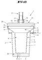
- a carbon dioxide removal region 36 is provided in addition to the filter region 35.
- This carbon dioxide removal region 36 is described in detail by an annular arrangement of a bed 37 of corresponding carbon dioxide removal agents, in the embodiment of soda lime granules, formed.
- This bed is preferably received in a basket part 38.
- the basket part 38 is further preferably formed annularly and moreover preferably arranged in a first section 8. It is in the embodiment of Fig. 10 arranged so that a bottom portion 39 of the basket member 38 above the filter portion 35, but with a small distance thereto, is located.
- it also depends on the filling level of the fluid, in particular of the water in the filter area 35. However, it is provided that as far as possible, the fluid does not extend to the bottom area 39.
- the basket area 38 can be closed by a cover part 40. So that the bed can not escape. But the cover part as well as the bottom part are preferably preferably flowed through, so for example. Grid or mesh-like, formed. The same also applies to the inner wall 41st
- the carbon dioxide removal region 36 has a total diameter f overall. With regard to these diameters, the preferred conditions described further above result.
- the air inlet and outlet openings 7 are further preferred in this embodiment, but this is also independent of the said horizontal design and / or the step-like transition of importance, of a setting part 43 overcame.
- the adjusting member 43 can by means of a downwardly and / or example. Side projecting, externally accessible Einstellvorsprung 44 be operable.
- the preferably circular ring-shaped adjusting member 43 can eino with a certain frictional resistance in the groove-like recess 45 preferably formed for this purpose.
- the setting can, for example, be provided by the fact that the air inlet and outlet openings are formed in the circumferential direction extending slot-like.
- a similar slot-like configuration may be formed in the adjustment member 43.
- By completely covering the slots a maximum passage can be achieved, and a minimum throughput can be achieved by using the greatest possible clearance. It can be provided that a minimum opening can not be undershot. It is also preferred that in the circumferential direction either the slots lie on different diameter ranges or are formed with such a distance given in the circumferential direction, that the corresponding Abschieberung is made possible.
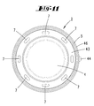
- Said elongated hole formation is in the plan view according to Fig. 11 again in more detail visible. Visible is the setting part 43, in a setting in which the slot openings in complete coverage to the underside provided in the outer part 2 corresponding slot openings is.
- the cover member 24, which is further preferred in this embodiment alone, is moreover preferably screwable to the outer part 2 in the region 46.
- an external thread can be formed on the outer part 2 in this region 46 and an internal thread on the cover part 24.
- the lid part 24 is formed with a, preferably cylindrical, receiving area 47, in which, in this embodiment, the bed 37 of carbon dioxide removal means is arranged is.
- a partial area t does not coincide with a free inner cross section of the lid part 24 with respect to the largest diameter of the carbon dioxide removal area, insofar as there is no or only little flow in the course of breathing.
- the bottom region 39 is preferably completely or essentially completely for covering the flow-through region of the splash guard 17, which is also preferably provided here.
- the inner diameter e is greater than a (largest) inner diameter of the inner part 8, regardless of the fact that the inner part 8 conically, widening upwards, is designed.
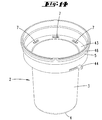
- the embodiment of the Fig. 12 essentially also further preferably consists only of the illustrated three parts, the cover part 24 with integrated receptacle of the carbon dioxide removal agent and the nested parts provided at the bottom part outer part 2 and the first section. 8
- the cover part 24 has only a very small vertical extent here. Outside the overlap area to the outer part 2 or to the first partial section 8, the vertical extent corresponds to only 1/20 to 1/3 of the vertical height of the outer part 2 or of the first partial section 8 until the start of the connecting section.
- the cover part 24 is here correspondingly designed without installation, in particular without a carbon dioxide removal agent. However, a splash guard may be provided.
- Fig. 14 In reference to Fig. 14 is the configuration of the outer part 2 and in particular also of the Einstellvorsprungs 44 of the embodiment of Fig. 10 to 13 to be recognized in further detail.
Landscapes
- Health & Medical Sciences (AREA)
- Pulmonology (AREA)
- General Health & Medical Sciences (AREA)
- Physical Education & Sports Medicine (AREA)
- Respiratory Apparatuses And Protective Means (AREA)
Priority Applications (1)
| Application Number | Priority Date | Filing Date | Title |
|---|---|---|---|
| EP12152281.7A EP2620186A1 (fr) | 2012-01-24 | 2012-01-24 | Appareil d'inhalation |
Applications Claiming Priority (1)
| Application Number | Priority Date | Filing Date | Title |
|---|---|---|---|
| EP12152281.7A EP2620186A1 (fr) | 2012-01-24 | 2012-01-24 | Appareil d'inhalation |
Publications (1)
| Publication Number | Publication Date |
|---|---|
| EP2620186A1 true EP2620186A1 (fr) | 2013-07-31 |
Family
ID=45509334
Family Applications (1)
| Application Number | Title | Priority Date | Filing Date |
|---|---|---|---|
| EP12152281.7A Withdrawn EP2620186A1 (fr) | 2012-01-24 | 2012-01-24 | Appareil d'inhalation |
Country Status (1)
| Country | Link |
|---|---|
| EP (1) | EP2620186A1 (fr) |
Citations (6)
| Publication number | Priority date | Publication date | Assignee | Title |
|---|---|---|---|---|
| US4114616A (en) * | 1976-06-07 | 1978-09-19 | Peter Nelson Brawn | Positive reinforcement respiratory inhalation device |
| WO1996019265A1 (fr) * | 1994-09-05 | 1996-06-27 | Ottestad Nils T | Procede et equipement d'apport d'air a faible niveau d'oxygene |
| CH687296A5 (fr) * | 1994-03-17 | 1996-11-15 | Guillermina Lugon | Dispositif pour exercices respiratoires. |
| US5755640A (en) * | 1996-12-04 | 1998-05-26 | Frolov; Vladimir F. | Endogenic breathing trainer |
| CN2510106Y (zh) * | 2001-12-25 | 2002-09-11 | 黑龙江省哈工大中俄科学技术合作有限公司 | 呼吸锻炼器 |
| US20020162560A1 (en) * | 1999-03-22 | 2002-11-07 | Rogacki Zenon Anthony | "X-Salizer" An exerciser for the lungs |
-
2012
- 2012-01-24 EP EP12152281.7A patent/EP2620186A1/fr not_active Withdrawn
Patent Citations (6)
| Publication number | Priority date | Publication date | Assignee | Title |
|---|---|---|---|---|
| US4114616A (en) * | 1976-06-07 | 1978-09-19 | Peter Nelson Brawn | Positive reinforcement respiratory inhalation device |
| CH687296A5 (fr) * | 1994-03-17 | 1996-11-15 | Guillermina Lugon | Dispositif pour exercices respiratoires. |
| WO1996019265A1 (fr) * | 1994-09-05 | 1996-06-27 | Ottestad Nils T | Procede et equipement d'apport d'air a faible niveau d'oxygene |
| US5755640A (en) * | 1996-12-04 | 1998-05-26 | Frolov; Vladimir F. | Endogenic breathing trainer |
| US20020162560A1 (en) * | 1999-03-22 | 2002-11-07 | Rogacki Zenon Anthony | "X-Salizer" An exerciser for the lungs |
| CN2510106Y (zh) * | 2001-12-25 | 2002-09-11 | 黑龙江省哈工大中俄科学技术合作有限公司 | 呼吸锻炼器 |
Similar Documents
| Publication | Publication Date | Title |
|---|---|---|
| DE2038618C3 (de) | Handbetätigtes Druck-Atmungsgerät | |
| DE69633306T2 (de) | Beatmungskreis für einen zerstäuber | |
| DE2938857C2 (de) | Sprühgerät | |
| DE60114393T2 (de) | Aerosolspender mit einer möglichkeit für positiven ausatemdruck | |
| DE2915683C2 (de) | Zweiwegeventil für den Anschluß eines Patienten an ein Atmungsgerät | |
| DE69523657T2 (de) | Vorrichtung zum Aufrechterhalten eines positiven Ausatemdruckes | |
| DE4011873B4 (de) | Hilfsgerät zur Verwendung mit einem Dosier-Aerosolgerät | |
| DE19902847C1 (de) | Medikamentenvernebler zur Inhalationsbehandlung mit kombiniertem Ein-/Ausatmungsventil | |
| DE2302110A1 (de) | Anaesthesievorrichtung | |
| DE2749160C2 (de) | Einstellbares Gerät für Atemübungen | |
| DE3043377A1 (de) | Zerstaeuber | |
| EP2489413A1 (fr) | Appareil de thérapie | |
| EP0610350A1 (fr) | Nebuliseur manuel pour la pulverisation de liquides therapeutiques. | |
| DE1491715A1 (de) | Inhalationsvorrichtung | |
| DE1766693B1 (de) | Inhalationsgeraet | |
| DE102010036625A1 (de) | Inhalationsgerät | |
| DE867143C (de) | Geraet zum Erzeugen von Gas-Dampf-Gemischen, besonders fuer Betaeubungszwecke | |
| EP2730293A1 (fr) | Filtre à gaz avev cuivre destiné à éliminer les bactéries et virus d'un volume de gaz | |
| EP2620186A1 (fr) | Appareil d'inhalation | |
| DE2434421A1 (de) | Vorrichtung zum verabreichen von pulvern | |
| DE1491849B1 (de) | Atmungsgeraet | |
| DE3827636A1 (de) | Atemtherapiegeraet | |
| DE3608933C2 (fr) | ||
| DE202015008332U1 (de) | Ansaugvorrichtung zur Nutzung von Bienenstockluft | |
| DE19903795B4 (de) | Atemtrainingsgerät zur Verbesserung der Vitalkapazität |
Legal Events
| Date | Code | Title | Description |
|---|---|---|---|
| PUAI | Public reference made under article 153(3) epc to a published international application that has entered the european phase |
Free format text: ORIGINAL CODE: 0009012 |
|
| AK | Designated contracting states |
Kind code of ref document: A1 Designated state(s): AL AT BE BG CH CY CZ DE DK EE ES FI FR GB GR HR HU IE IS IT LI LT LU LV MC MK MT NL NO PL PT RO RS SE SI SK SM TR |
|
| AX | Request for extension of the european patent |
Extension state: BA ME |
|
| STAA | Information on the status of an ep patent application or granted ep patent |
Free format text: STATUS: THE APPLICATION IS DEEMED TO BE WITHDRAWN |
|
| 18D | Application deemed to be withdrawn |
Effective date: 20140201 |