EP2620202A1 - Procédé et appareil de surveillance de condition de filtre à air - Google Patents
Procédé et appareil de surveillance de condition de filtre à air Download PDFInfo
- Publication number
- EP2620202A1 EP2620202A1 EP12153017.4A EP12153017A EP2620202A1 EP 2620202 A1 EP2620202 A1 EP 2620202A1 EP 12153017 A EP12153017 A EP 12153017A EP 2620202 A1 EP2620202 A1 EP 2620202A1
- Authority
- EP
- European Patent Office
- Prior art keywords
- dirt
- basis
- present
- fan
- determining
- Prior art date
- Legal status (The legal status is an assumption and is not a legal conclusion. Google has not performed a legal analysis and makes no representation as to the accuracy of the status listed.)
- Granted
Links
Images


Classifications
-
- B—PERFORMING OPERATIONS; TRANSPORTING
- B01—PHYSICAL OR CHEMICAL PROCESSES OR APPARATUS IN GENERAL
- B01D—SEPARATION
- B01D46/00—Filters or filtering processes specially modified for separating dispersed particles from gases or vapours
- B01D46/0084—Filters or filtering processes specially modified for separating dispersed particles from gases or vapours provided with safety means
- B01D46/0086—Filter condition indicators
-
- B—PERFORMING OPERATIONS; TRANSPORTING
- B01—PHYSICAL OR CHEMICAL PROCESSES OR APPARATUS IN GENERAL
- B01D—SEPARATION
- B01D46/00—Filters or filtering processes specially modified for separating dispersed particles from gases or vapours
- B01D46/42—Auxiliary equipment or operation thereof
- B01D46/44—Auxiliary equipment or operation thereof controlling filtration
- B01D46/444—Auxiliary equipment or operation thereof controlling filtration by flow measuring
-
- G—PHYSICS
- G01—MEASURING; TESTING
- G01N—INVESTIGATING OR ANALYSING MATERIALS BY DETERMINING THEIR CHEMICAL OR PHYSICAL PROPERTIES
- G01N15/00—Investigating characteristics of particles; Investigating permeability, pore-volume or surface-area of porous materials
- G01N15/08—Investigating permeability, pore-volume, or surface area of porous materials
- G01N15/082—Investigating permeability by forcing a fluid through a sample
-
- F—MECHANICAL ENGINEERING; LIGHTING; HEATING; WEAPONS; BLASTING
- F04—POSITIVE - DISPLACEMENT MACHINES FOR LIQUIDS; PUMPS FOR LIQUIDS OR ELASTIC FLUIDS
- F04D—NON-POSITIVE-DISPLACEMENT PUMPS
- F04D27/00—Control, e.g. regulation, of pumps, pumping installations or pumping systems specially adapted for elastic fluids
- F04D27/001—Testing thereof; Determination or simulation of flow characteristics; Stall or surge detection, e.g. condition monitoring
-
- F—MECHANICAL ENGINEERING; LIGHTING; HEATING; WEAPONS; BLASTING
- F24—HEATING; RANGES; VENTILATING
- F24F—AIR-CONDITIONING; AIR-HUMIDIFICATION; VENTILATION; USE OF AIR CURRENTS FOR SCREENING
- F24F11/00—Control or safety arrangements
- F24F11/70—Control systems characterised by their outputs; Constructional details thereof
- F24F11/72—Control systems characterised by their outputs; Constructional details thereof for controlling the supply of treated air, e.g. its pressure
- F24F11/74—Control systems characterised by their outputs; Constructional details thereof for controlling the supply of treated air, e.g. its pressure for controlling air flow rate or air velocity
- F24F11/77—Control systems characterised by their outputs; Constructional details thereof for controlling the supply of treated air, e.g. its pressure for controlling air flow rate or air velocity by controlling the speed of ventilators
-
- F—MECHANICAL ENGINEERING; LIGHTING; HEATING; WEAPONS; BLASTING
- F24—HEATING; RANGES; VENTILATING
- F24F—AIR-CONDITIONING; AIR-HUMIDIFICATION; VENTILATION; USE OF AIR CURRENTS FOR SCREENING
- F24F11/00—Control or safety arrangements
- F24F11/70—Control systems characterised by their outputs; Constructional details thereof
- F24F11/72—Control systems characterised by their outputs; Constructional details thereof for controlling the supply of treated air, e.g. its pressure
- F24F11/79—Control systems characterised by their outputs; Constructional details thereof for controlling the supply of treated air, e.g. its pressure for controlling the direction of the supplied air
-
- F—MECHANICAL ENGINEERING; LIGHTING; HEATING; WEAPONS; BLASTING
- F24—HEATING; RANGES; VENTILATING
- F24F—AIR-CONDITIONING; AIR-HUMIDIFICATION; VENTILATION; USE OF AIR CURRENTS FOR SCREENING
- F24F3/00—Air-conditioning systems in which conditioned primary air is supplied from one or more central stations to distributing units in the rooms or spaces where it may receive secondary treatment; Apparatus specially designed for such systems
- F24F3/12—Air-conditioning systems in which conditioned primary air is supplied from one or more central stations to distributing units in the rooms or spaces where it may receive secondary treatment; Apparatus specially designed for such systems characterised by the treatment of the air otherwise than by heating and cooling
- F24F3/16—Air-conditioning systems in which conditioned primary air is supplied from one or more central stations to distributing units in the rooms or spaces where it may receive secondary treatment; Apparatus specially designed for such systems characterised by the treatment of the air otherwise than by heating and cooling by purification, e.g. by filtering; by sterilisation; by ozonisation
- F24F3/167—Clean rooms, i.e. enclosed spaces in which a uniform flow of filtered air is distributed
-
- H—ELECTRICITY
- H10—SEMICONDUCTOR DEVICES; ELECTRIC SOLID-STATE DEVICES NOT OTHERWISE PROVIDED FOR
- H10P—GENERIC PROCESSES OR APPARATUS FOR THE MANUFACTURE OR TREATMENT OF DEVICES COVERED BY CLASS H10
- H10P72/00—Handling or holding of wafers, substrates or devices during manufacture or treatment thereof
- H10P72/06—Apparatus for monitoring, sorting, marking, testing or measuring
- H10P72/0604—Process monitoring, e.g. flow or thickness monitoring
-
- Y—GENERAL TAGGING OF NEW TECHNOLOGICAL DEVELOPMENTS; GENERAL TAGGING OF CROSS-SECTIONAL TECHNOLOGIES SPANNING OVER SEVERAL SECTIONS OF THE IPC; TECHNICAL SUBJECTS COVERED BY FORMER USPC CROSS-REFERENCE ART COLLECTIONS [XRACs] AND DIGESTS
- Y02—TECHNOLOGIES OR APPLICATIONS FOR MITIGATION OR ADAPTATION AGAINST CLIMATE CHANGE
- Y02B—CLIMATE CHANGE MITIGATION TECHNOLOGIES RELATED TO BUILDINGS, e.g. HOUSING, HOUSE APPLIANCES OR RELATED END-USER APPLICATIONS
- Y02B30/00—Energy efficient heating, ventilation or air conditioning [HVAC]
- Y02B30/70—Efficient control or regulation technologies, e.g. for control of refrigerant flow, motor or heating
Definitions
- the invention relates to air filter condition monitoring, and particularly to accurately estimating accumulation of dirt in a filter.
- Fans and blowers are widely used in ventilation applications. They consume a large share of all electrical energy used in industry and in service sector. Majority of life-cycle costs of a fan system can be energy costs.
- the fan system is typically equipped with an air filter, for instance, to maintain performance of a heat exchanger.
- the filter can cause an additional pressure drop in the ventilation system, thus, decreasing the efficiency of the fan system.
- the efficiency can, for instance, be represented by the specific fan power SFP (kW/m 3 /s) which represents power consumption as a function of the flow rate.
- SFP kW/m 3 /s
- an initial pressure drop may, for instance, be approximately 50 to 100 Pa when the final pressure at the time of filter change is 200 to 250 Pa.
- air filters are responsible for a large portion of total pressure drop in ventilation systems.
- condition monitoring of an air filter may be carried out by measuring a pressure difference over the air filter.
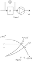
- Figure 1 illustrates an exemplary ventilation fan 10 with an air filter 11. The condition of the air filter is monitored by a pressure difference measurement 12. An increasing pressure difference indicates accumulation of dirt in the air filter 11.
- An object of the present invention is to provide a method and an apparatus for alleviating the above disadvantages.
- the objects of the invention are achieved by a method and an apparatus which are characterized by what is stated in the independent claims.
- the preferred embodiments of the invention are disclosed in the dependent claims.
- Accumulation of dirt on an air filter in a ventilation system comprising the filter and a fan can be accurately detected under different operating conditions by using the disclosed method.
- Amount of dirt in the filter can be estimated on the basis of the effect the dirt has on the operating point of the fan.
- the operating point can be estimated on the basis of characteristics curves and power of the fan.
- the power can be estimated on the basis of a mechanical torque and a rotational speed of the fan.
- a filter pressure loss induced by the dirt can be estimated.
- a specific fan power representing power consumption in respect of a flow rate through the fan can also be calculated on the basis of the operating point.
- Yet another alternative is to calculate a power loss induced by the dirt accumulating on the filter on the basis of the operating point.
- the disclosed method is able to accurately detect accumulation of dirt even if the fan system operates under different operating conditions.
- the accumulation of dirt can be estimated without cost-increasing pressure sensors.
- the following paragraphs disclose a method and apparatus for monitoring accumulation of dirt on an air filter of a ventilation system comprising an air filter and a fan controlled by a frequency converter. Amount of dirt in the filter can be estimated on the basis of the effect the dirt has on the operating point of the fan.
- the accumulated dirt can be considered to influence the operating point through its effect on a process curve of the ventilation system.
- the process curve describes the pressure difference (system losses) p over the system as a function of the flow rate Q through the system.
- the operating point of a fan system is located at the intersection of a Qp -characteristics curve of the fan and the process curve.
- the Qp- characteristics curve represents a relation between flow rate and pressure at a certain rotational speed.
- the dynamic resistance factor increases as dirt accumulates on an air filter. A change in the dynamic resistance causes a change in the process curve, and, as a consequence, the location of the intersection the Qp -characteristics curve and the process curve. In other words, the operating point shifts.
- Figure 2 illustrates an effect accumulating dirt has on the process curve of an exemplary fan system.
- an initial value A for the operating point of the fan system is illustrated at the intersection of the Qp- characteristics curve at the used rotational speed and the initial process curve with an initial dynamic resistance factor k 0 .
- a flow rate Q 0 produces a pressure difference p 0 .
- the dynamic resistance factor increases to value k 0 + k dirt .
- the rotational speed is assumed to remain the same, the operating point moves to the new intersection B of the process curve and the characteristics curve.
- increase k dirt in the dynamic resistance causes the operation point to move so that the flow rate decreases (to value Q 1 ) and the pressure difference increases (to value p 1 ).
- the operating point of a fan can be estimated by using characteristics curves of the fan and the power of the fan.
- the power P est can be estimated on the basis of the present mechanical torque and the rotational speed of the fan.
- P est 2 ⁇ ⁇ ⁇ n est 60 ⁇ T est , where n est is an estimated rotational speed and T est is an estimated torque. These estimates may be available from the frequency converter.
- the characteristics curves may comprise the Q p-characteristics curve and a QP -characteristics curve which represents a relation between flow rate and power.
- the Q P-characteristics curve and the Q p-characteristics curve may both be single curves representing the fan characteristics at a certain rotational speed, or one or both of them may be sets of curves representing the fan characteristics at a plurality of rotational speeds.
- the fan may well operate on other rotational speed than what is given in the characteristics curves.
- Figures 3a and 3b illustrate exemplary characteristics curves.
- curves at nominal rotational speed are illustrated using a solid line.
- Curves calculated using the affinity laws are illustrated with a dashed line.
- a flow rate through the filter and the fan may be estimated on the basis of the mechanical power, the rotational speed, and a Q P-characteristics curve.
- Figure 3a shows a Q P-characteristics curve from which the flow rate can be determined.
- Determining the operating point may also comprise estimating a pressure difference over the filter system on the basis of the estimated flow rate, the rotational speed, and a Qp -characteristics curve.
- the pressure difference can, for instance, be determined by using the Qp -characteristics curve in Figure 3b and the determined flow rate.
- the operating point can then be used to calculate values for some operating parameters of the fan system, such as the dynamic resistance of the fan system or a specific fan power.
- the air filter condition can be monitored without additional sensors by calculating an effect the movement of the operating point has on the operating parameter.
- the dynamic resistance or the specific fan power consumption can by themselves serve as an indicator for accumulation of dirt.
- a filter pressure loss induced by the dirt can further be estimated on the basis of a change in the dynamic resistance.
- a power loss induced by the dirt accumulating on the filter can be estimated on the basis of the dynamic resistance.
- the estimates can, for instance, be normalized to express values in relation to a nominal flow rate of the fan.
- the disclosed method and apparatus may, for instance, operate as described in the following paragraphs.
- Characteristics curves of the fan and the initial operating conditions are first determined in order to be able to detect a change in operating conditions.
- An initial value for the operating parameter can be determined and stored so that it can serve as a reference value representing a clean filter.
- the operating parameter can, for instance, be the dynamic resistance of the fan system or the specific fan power consumption.
- the initial value for the operating parameter can, for instance, be determined on the basis of an estimated initial operating point.
- the initial operating point can be estimated using the above disclosed means.
- the present operating point can then be determined.
- the present torque and rotational speed of the fan can first be determined.
- a mechanical power of the fan can be estimated on the basis of the torque and the rotational speed.
- the present operating point can then be estimated on the basis of the characteristics curves, the mechanical power, and the present rotational speed. For instance, a present flow rate through the filter and the fan may be estimated on the basis of the mechanical power, the rotational speed, and a QP -characteristics curve.
- a present pressure difference over the filter system may also be estimated on the basis of the estimated flow rate, the rotational speed, and a Qp -characteristics curve.
- the present value for the operating parameter can then be determined on the basis of the present operating point. Finally, accumulation of dirt on the air filter can be determined on the basis of the initial and present values of the operating parameter.
- Figure 4 illustrates an exemplary embodiment of a ventilation system 40 comprising an air filter 41 and a fan 42 controlled by a frequency converter 43.
- air travels through the air filter 41 and the fan 42.
- An apparatus is used for estimating accumulation of dirt on the air filter 41 on the basis of the effect the dirt has on the operating point of the fan 42.
- the apparatus is implemented in the frequency converter 43. However, in some embodiments, the apparatus may also be a separate device.
- the characteristics curves Q p and QP are determined by storing their values in the memory of the frequency converter 43.
- the frequency converter 43 comprises means configured to determine an initial value for the operating parameter.
- an estimated torque n est and an estimated rotational speed T est are available from the frequency converter 43, and the frequency converter 43 comprises means configured to determine an estimate of a mechanical power of the fan on the basis of the torque and the rotational speed and means configured to determine a present operating point on the basis of the characteristics curves, the mechanical power, and the rotational speed.
- the frequency converter 43 further comprises means configured to determine the present value for the operating parameter on the basis of the present operating point, and to determine accumulation of dirt on the air filter on the basis of the initial and present values of the operating parameter. If the frequency converter 43 determines that the amount of dirt has exceeded an allowable level, it sends an alert.
- the specific fan power consumption is used as the operating parameter. Determining the present operating point comprises a previously disclosed step of estimating the flow rate.
- Accumulation of dirt on the air filter can be determined by calculating a difference between the initial specific fan power consumption and the present specific fan power. The calculated difference can be compared to a set limit, and the accumulation of dirt can finally be determined on the basis of the comparison result. For example, if the value of the SFP exceeds the set limit, the method or apparatus can detect that a certain level of dirt has accumulated in the filter and inform the maintenance personnel.
- the operating parameter represents the dynamic resistance.
- the embodiment performs the previously disclosed steps for estimating the flow rate and the pressure difference.
- the present value for the operating parameter can then be determined by estimating the dynamic resistance on the basis of the estimated flow rate Q est and pressure difference p est .
- determining accumulation of dirt on the air filter can comprise calculating a change in the dynamic resistance induced by the dirt on the basis of the initial dynamic resistance and the present dynamic resistance, wherein the initial dynamic resistance represents the system resistance in a system with a clean filter.
- the calculated change can be compared to a set limit, and accumulation of dirt can be directly determined on the basis of the comparison result.
- the dynamic resistance difference k dirt represents the difference between the initial and present dynamic resistance induced by the dirt.
- the estimated pressure loss p d , dirt can be compared with a set limit, and accumulation of dirt can be determined on the basis of the comparison result. For instance, if the calculated pressure loss exceeds 150 Pa, the method or apparatus can inform maintenance personnel that the filter should be cleaned or changed.
- a power loss P loss,dirt induced by the dirt at a nominal rotational speed n 0 is calculated on the basis of the dynamic resistance difference k dirt induced by the dirt.
- the power loss can then be compared with a set limit, and the accumulation of dirt can be determined on the basis of the comparison result.
- Figure 5 illustrates measurement results.
- An actual process curve of the system with a clean filter is illustrated using a dashed line.
- Small crosses show estimated operating points with a clean filter.
- An actual process curve of the system with a dirty filter is illustrated using a solid line.
- Small circles show estimated operating points with a dirty filter.
- Table 1 shows the system dynamic resistance and pressure loss at different rotational speeds.
- the pressure loss was calculated for a nominal flow of 1.5 m 3 /s.
- the estimated dynamic resistance clearly changed responsive to the rotational speed even though the actual dynamic resistance stayed the same.
- the pressure loss is directly dependent on the dynamic resistance, so the pressure loss estimates were not the same at different rotational speeds but changed together with the dynamic resistance.
- the estimated dynamic resistances of the clean filter and the dirty remained comparable with each other.
- the disclosed method can thus be used for estimating accumulation of dirt by comparing the two dynamic resistances. Between a clear filter and a dirty filter, a clear change in the dynamic resistance and pressure loss can be observed in Table 1.
- Table 2 shows the estimated specific fan power SFP 0 . Accumulation of dirt caused a significant change in the estimated specific fan power SFP 0 at every rotational speed of Table 2.
- Table 2 Rotational speed (rpm) 600 750 900 1050 1200 1350 1500 1650 1800 Measured SFP 0 clean 2.2 2.3 2.4 2.4 2.4 2.5 2.4 2.6 2.6 SFP 0 dirty 2.6 2.8 3.0 3.1 3.1 3.2 3.3 3.5 3.8 ⁇ SFP 0 0.4 0.5 0.6 0.7 0.7 0.7 0.9 1.1 1.2
- the specific fan power of a clean filter at 1800 rpm was the same as the specific fan power of the dirty filter at 600 rpm.
- the different values in the estimated specific fan powers were, again, caused by the inaccuracy in estimating the flow rate.
- the characteristics curves and the estimation of the dynamic resistance can be divided into separate rotational speed zones.
- the characteristic curves can be represented by two sets of curves.
- the curves in each set of curves may, for instance, be less than 10% of their nominal rotational speed apart from their adjacent curves.
- the curve in a set of characteristics curves having the closest matching rotational speed can first be selected and then the affinity laws together with the actual rotational speed can be used for calculating the flow rate.
- the increase on the power loss is apparent at every rotational speed, and, thus, it can directly be used as an indicator of dirt in the filter.
Landscapes
- Chemical & Material Sciences (AREA)
- Chemical Kinetics & Catalysis (AREA)
- Biochemistry (AREA)
- Health & Medical Sciences (AREA)
- Life Sciences & Earth Sciences (AREA)
- Analytical Chemistry (AREA)
- Physics & Mathematics (AREA)
- General Health & Medical Sciences (AREA)
- General Physics & Mathematics (AREA)
- Immunology (AREA)
- Pathology (AREA)
- Dispersion Chemistry (AREA)
- Air Conditioning Control Device (AREA)
- Control Of Positive-Displacement Air Blowers (AREA)
- Filtering Of Dispersed Particles In Gases (AREA)
Priority Applications (3)
| Application Number | Priority Date | Filing Date | Title |
|---|---|---|---|
| EP12153017.4A EP2620202B1 (fr) | 2012-01-30 | 2012-01-30 | Procédé et appareil de surveillance de condition de filtre à air |
| US13/749,403 US9200995B2 (en) | 2012-01-30 | 2013-01-24 | Method and apparatus for monitoring air filter condition |
| CN201310034763.3A CN103223275B (zh) | 2012-01-30 | 2013-01-29 | 用于监视空气过滤器状态的方法以及设备 |
Applications Claiming Priority (1)
| Application Number | Priority Date | Filing Date | Title |
|---|---|---|---|
| EP12153017.4A EP2620202B1 (fr) | 2012-01-30 | 2012-01-30 | Procédé et appareil de surveillance de condition de filtre à air |
Publications (3)
| Publication Number | Publication Date |
|---|---|
| EP2620202A1 true EP2620202A1 (fr) | 2013-07-31 |
| EP2620202A9 EP2620202A9 (fr) | 2013-09-11 |
| EP2620202B1 EP2620202B1 (fr) | 2014-10-29 |
Family
ID=45562117
Family Applications (1)
| Application Number | Title | Priority Date | Filing Date |
|---|---|---|---|
| EP12153017.4A Active EP2620202B1 (fr) | 2012-01-30 | 2012-01-30 | Procédé et appareil de surveillance de condition de filtre à air |
Country Status (3)
| Country | Link |
|---|---|
| US (1) | US9200995B2 (fr) |
| EP (1) | EP2620202B1 (fr) |
| CN (1) | CN103223275B (fr) |
Cited By (4)
| Publication number | Priority date | Publication date | Assignee | Title |
|---|---|---|---|---|
| EP2960484A1 (fr) * | 2014-06-27 | 2015-12-30 | FPT Motorenforschung AG | Système pour détecter un état de filtre à air, en particulier pour moteurs à combustion interne |
| EP3858459A1 (fr) * | 2020-02-03 | 2021-08-04 | Piovan S.P.A. | Procédé et appareil de filtration |
| WO2021252437A1 (fr) * | 2020-06-08 | 2021-12-16 | Vitality Ventures HK Company Limited | Procédé de prédiction de durée de vie de filtre et procédé de détection de type de filtre |
| EP3927977A1 (fr) * | 2019-08-17 | 2021-12-29 | Ziehl-Abegg Se | Procédé de détermination quantitative d'une grandeur réelle dépendante de l'état de fonctionnement d'un ventilateur, en particulier d'un changement de pression ou d'une augmentation de pression, et ventilateur |
Families Citing this family (20)
| Publication number | Priority date | Publication date | Assignee | Title |
|---|---|---|---|---|
| CN104165830A (zh) * | 2013-05-16 | 2014-11-26 | 鸿富锦精密工业(深圳)有限公司 | 服务器粉尘监测系统和方法 |
| CN104833051A (zh) * | 2015-04-28 | 2015-08-12 | 广东美的制冷设备有限公司 | 滤网积尘程度检测方法和装置、空气调节设备 |
| CN104833050B (zh) * | 2015-04-28 | 2017-12-22 | 广东美的制冷设备有限公司 | 空气调节器及其过滤网积尘程度的检测装置、方法 |
| US10302325B1 (en) * | 2016-04-25 | 2019-05-28 | American Air Filter Company, Inc. | Air filter operation and use modification according to identify a filter resistance of an air handling unit |
| US20180031290A1 (en) * | 2016-07-28 | 2018-02-01 | Hamilton Sundstrand Corporation | Vapor cycle refrigeration system filter life estimation |
| JP7035011B2 (ja) | 2016-08-08 | 2022-03-14 | スリーエム イノベイティブ プロパティズ カンパニー | 空気フィルタの状態感知 |
| US10933713B2 (en) * | 2016-12-27 | 2021-03-02 | Cnh Industrial America Llc | Airflow control system of a work vehicle |
| DE102017101695A1 (de) | 2017-01-30 | 2018-08-02 | Ebm-Papst Mulfingen Gmbh & Co. Kg | Vorrichtung und ein Verfahren zur Detektion einer Filterverstopfung |
| CN107514740A (zh) * | 2017-07-24 | 2017-12-26 | 珠海格力电器股份有限公司 | 过滤式机组的过滤器寿命判断方法及过滤式机组 |
| CN110241592B (zh) * | 2018-03-09 | 2022-12-27 | 青岛海尔洗涤电器有限公司 | 一种衣物处理设备控制方法及衣物处理设备 |
| US11676047B1 (en) | 2018-10-25 | 2023-06-13 | 3M Innovative Properties Company | Air quality data servicing |
| US11841022B2 (en) | 2020-01-06 | 2023-12-12 | Regal Beloit America, Inc. | Control system for electric fluid moving apparatus |
| US10731889B2 (en) * | 2019-01-08 | 2020-08-04 | Regal Beloit America, Inc. | Motor controller for electric blowers |
| CN111878969B (zh) * | 2020-05-25 | 2022-03-01 | 宁波奥克斯电气股份有限公司 | 一种滤网脏堵检测控制方法、装置、空调及可读存储介质 |
| DE102020118251A1 (de) | 2020-07-10 | 2022-01-13 | Ebm-Papst Mulfingen Gmbh & Co. Kg | Verfahren und Ventilatorsystem zur Ermittlung des Zustands eines Filters in einer Ventilatoreinheit |
| CN113486953B (zh) * | 2021-07-06 | 2024-10-15 | 茵梦达(上海)电气传动设备有限公司 | 变频器滤网更换时间的预测方法、装置及计算机可读介质 |
| CN114136530B (zh) * | 2021-11-23 | 2023-10-13 | 中国铁道科学研究院集团有限公司 | 确定变流器进出口空气压力差的方法及装置 |
| EP4197617A1 (fr) * | 2021-12-20 | 2023-06-21 | Versuni Holding B.V. | Nettoyage de filtre d'un dispositif de traitement d'air |
| US11708986B1 (en) * | 2022-07-12 | 2023-07-25 | Intellytic Ventures Ltd | Smart IoT energy saving sound wave air filter system and use for air purifiers and a method of air filtration thereof |
| WO2025061629A1 (fr) * | 2023-09-19 | 2025-03-27 | Deltrian International Sa | Procédé de détermination d'un indicateur de décision pour la sélection d'un filtre à air optimal et procédé de maintenance prédictive du filtre |
Citations (7)
| Publication number | Priority date | Publication date | Assignee | Title |
|---|---|---|---|---|
| US4786295A (en) * | 1987-10-01 | 1988-11-22 | Gpac, Inc. | Filtration device for airborne contaminants |
| US6448896B1 (en) * | 2001-08-24 | 2002-09-10 | Carrier Corporation | Air filter monitor for HVAC units |
| US6582295B1 (en) * | 1999-06-30 | 2003-06-24 | Valeo Climatisation | Method of detecting clogging of an air filter and ventilation system employing such a method |
| US20050188842A1 (en) * | 2004-02-26 | 2005-09-01 | Chia-Chang Hsieh | Method for detecting the cleanliness of a filter |
| US20050247194A1 (en) * | 2004-05-06 | 2005-11-10 | Pengju Kang | Technique for detecting and predicting air filter condition |
| DE102005023371A1 (de) * | 2005-05-20 | 2006-11-30 | Siemens Ag | Verfahren und Anordnung zur Bestimmung eines Austauschkriteriums für ein Luftfilter |
| EP1800919A2 (fr) * | 2005-12-26 | 2007-06-27 | Sanden Corporation | Dispositif de filtrage d'air et systèmes de climatisation pour véhicule et machine de construction utilisant cette machine |
Family Cites Families (11)
| Publication number | Priority date | Publication date | Assignee | Title |
|---|---|---|---|---|
| EP0479609A3 (en) * | 1990-10-05 | 1993-01-20 | Hitachi, Ltd. | Vacuum cleaner and control method thereof |
| DE19726547A1 (de) * | 1997-06-23 | 1999-01-28 | Babcock Bsh Gmbh | Verfahren zur Bestimmung des Betriebspunktes eines Ventilators und Ventilator |
| SE523865C2 (sv) * | 2000-05-02 | 2004-05-25 | Bengt Steneby | Ventilationsapparat för zonvis ventilation innefattande värmeväxlare för till- och frånluft samt sensorer för att bestämma luftflödenas relativa hastighetsavvikelse i resp kanal |
| DE50111285D1 (de) * | 2000-08-30 | 2006-11-30 | Ebm Papst St Georgen Gmbh & Co | Verfahren zum regeln des stromes in einer gleichstrommaschine für einen lüfter |
| WO2002019510A1 (fr) * | 2000-08-30 | 2002-03-07 | Papst-Motoren Gmbh & Co. Kg | Generatrice a courant continu avec dispositif de limitation de courant regulable |
| JP4038352B2 (ja) * | 2001-08-24 | 2008-01-23 | 株式会社日立産機システム | クリーンルーム |
| JP4523803B2 (ja) * | 2004-06-30 | 2010-08-11 | 富士通株式会社 | ファンシステム、ファン装置、及びファン装置の制御方法 |
| US8739564B2 (en) * | 2008-03-18 | 2014-06-03 | GM Global Technology Operations LLC | Controlling temperature of vehicle devices using a variable speed fan |
| DE102008041325A1 (de) * | 2008-08-19 | 2010-02-25 | Robert Bosch Gmbh | Elektromotorbaugruppe, Verfahren zum Betreiben eines Elektromotors sowie Motorsteuereinrichtung |
| JP5409544B2 (ja) * | 2010-08-04 | 2014-02-05 | 三菱電機株式会社 | 空気調和機の室内機、及び空気調和機 |
| ES2643743T3 (es) * | 2013-04-30 | 2017-11-24 | Gidelmar, S.A. | Método y sistema de ajuste automático del funcionamiento de un ventilador, y programa de ordenador que implementa el método |
-
2012
- 2012-01-30 EP EP12153017.4A patent/EP2620202B1/fr active Active
-
2013
- 2013-01-24 US US13/749,403 patent/US9200995B2/en active Active
- 2013-01-29 CN CN201310034763.3A patent/CN103223275B/zh active Active
Patent Citations (7)
| Publication number | Priority date | Publication date | Assignee | Title |
|---|---|---|---|---|
| US4786295A (en) * | 1987-10-01 | 1988-11-22 | Gpac, Inc. | Filtration device for airborne contaminants |
| US6582295B1 (en) * | 1999-06-30 | 2003-06-24 | Valeo Climatisation | Method of detecting clogging of an air filter and ventilation system employing such a method |
| US6448896B1 (en) * | 2001-08-24 | 2002-09-10 | Carrier Corporation | Air filter monitor for HVAC units |
| US20050188842A1 (en) * | 2004-02-26 | 2005-09-01 | Chia-Chang Hsieh | Method for detecting the cleanliness of a filter |
| US20050247194A1 (en) * | 2004-05-06 | 2005-11-10 | Pengju Kang | Technique for detecting and predicting air filter condition |
| DE102005023371A1 (de) * | 2005-05-20 | 2006-11-30 | Siemens Ag | Verfahren und Anordnung zur Bestimmung eines Austauschkriteriums für ein Luftfilter |
| EP1800919A2 (fr) * | 2005-12-26 | 2007-06-27 | Sanden Corporation | Dispositif de filtrage d'air et systèmes de climatisation pour véhicule et machine de construction utilisant cette machine |
Non-Patent Citations (1)
| Title |
|---|
| RECOMMENDATION CONCERNING CALCULATING LIFE CYCLE COST FOR AIR FILTERS, EU- ROVENT, September 2005 (2005-09-01) |
Cited By (5)
| Publication number | Priority date | Publication date | Assignee | Title |
|---|---|---|---|---|
| EP2960484A1 (fr) * | 2014-06-27 | 2015-12-30 | FPT Motorenforschung AG | Système pour détecter un état de filtre à air, en particulier pour moteurs à combustion interne |
| US10126203B2 (en) | 2014-06-27 | 2018-11-13 | Fpt Motorenforschung Ag | System for detecting an air filter condition, in particular for combustion engine |
| EP3927977A1 (fr) * | 2019-08-17 | 2021-12-29 | Ziehl-Abegg Se | Procédé de détermination quantitative d'une grandeur réelle dépendante de l'état de fonctionnement d'un ventilateur, en particulier d'un changement de pression ou d'une augmentation de pression, et ventilateur |
| EP3858459A1 (fr) * | 2020-02-03 | 2021-08-04 | Piovan S.P.A. | Procédé et appareil de filtration |
| WO2021252437A1 (fr) * | 2020-06-08 | 2021-12-16 | Vitality Ventures HK Company Limited | Procédé de prédiction de durée de vie de filtre et procédé de détection de type de filtre |
Also Published As
| Publication number | Publication date |
|---|---|
| EP2620202A9 (fr) | 2013-09-11 |
| CN103223275B (zh) | 2015-11-25 |
| CN103223275A (zh) | 2013-07-31 |
| US9200995B2 (en) | 2015-12-01 |
| EP2620202B1 (fr) | 2014-10-29 |
| US20130197826A1 (en) | 2013-08-01 |
Similar Documents
| Publication | Publication Date | Title |
|---|---|---|
| EP2620202B1 (fr) | Procédé et appareil de surveillance de condition de filtre à air | |
| US10066631B2 (en) | Direct power control for constant airflow control | |
| US9732976B2 (en) | Direct power control for constant airflow control with advanced motor system modeling | |
| EP3109573B1 (fr) | Cartographie croisée de composants dans un système de réfrigération | |
| KR101815408B1 (ko) | 팬 모터의 풍량 측정 방법 | |
| US20100204945A1 (en) | System and Method for Detecting Fluid Delivery System Conditions Based on Motor Parameters | |
| KR102376355B1 (ko) | 필터의 교체주기 간 수명의 최적화 방법 및 환기 시스템의 모니터링 시스템 | |
| CN105359045A (zh) | 用于估计电动马达的使用寿命的装置 | |
| KR20120074179A (ko) | 전동기의 예방 보전 장치 | |
| EP2799789B1 (fr) | Procédé et système permettant de régler automatiquement le fonctionnement d'un ventilateur et programme informatique mettant en 'uvre ledit procédé | |
| RU2432591C2 (ru) | Способ управления для охлаждения технической установки | |
| CN107560097A (zh) | 空调设备的模块温度传感器检测方法和装置 | |
| EP2565465B1 (fr) | Procédé et appareil pour déterminer le changement de masse d'une roue de ventilateur | |
| US8186230B1 (en) | System and method for airflow sensing and monitoring | |
| CN110701727A (zh) | 用于检测hvac系统中故障的方法和系统以及存储器 | |
| CN101033744B (zh) | 不使用传统传感器的泵保护方法和设备 | |
| CN107192099A (zh) | 空调及其积尘判断方法和积尘判断装置以及积尘判断系统 | |
| CN106050638A (zh) | 一种压缩机运行范围的评估方法及装置 | |
| EP2505848B1 (fr) | Détection de décollement dans des ventilateurs au moyen d'un convertisseur de fréquence | |
| JP2002319426A (ja) | 燃料電池システム用の冷却液の品質を管理する方法 | |
| WO2013159458A1 (fr) | Moteur et procédé de commande à volume d'air constant pour système de ventilateur de climatisation | |
| CN101499692A (zh) | 旋转电机及发电系统 | |
| JP6381282B2 (ja) | 異常検出装置及びプログラム | |
| Tamminen et al. | Sensorless flow rate estimation in frequency-converter-driven fans | |
| Pöyhönen et al. | Variable-speed-drive-based estimation of the pressure drop caused by filter fouling in fan systems |
Legal Events
| Date | Code | Title | Description |
|---|---|---|---|
| PUAI | Public reference made under article 153(3) epc to a published international application that has entered the european phase |
Free format text: ORIGINAL CODE: 0009012 |
|
| AK | Designated contracting states |
Kind code of ref document: A1 Designated state(s): AL AT BE BG CH CY CZ DE DK EE ES FI FR GB GR HR HU IE IS IT LI LT LU LV MC MK MT NL NO PL PT RO RS SE SI SK SM TR |
|
| AX | Request for extension of the european patent |
Extension state: BA ME |
|
| 17P | Request for examination filed |
Effective date: 20140130 |
|
| RBV | Designated contracting states (corrected) |
Designated state(s): AL AT BE BG CH CY CZ DE DK EE ES FI FR GB GR HR HU IE IS IT LI LT LU LV MC MK MT NL NO PL PT RO RS SE SI SK SM TR |
|
| GRAP | Despatch of communication of intention to grant a patent |
Free format text: ORIGINAL CODE: EPIDOSNIGR1 |
|
| INTG | Intention to grant announced |
Effective date: 20140612 |
|
| GRAS | Grant fee paid |
Free format text: ORIGINAL CODE: EPIDOSNIGR3 |
|
| GRAA | (expected) grant |
Free format text: ORIGINAL CODE: 0009210 |
|
| RIN1 | Information on inventor provided before grant (corrected) |
Inventor name: TAMMINEN, JUSSI Inventor name: AHOLA, JERO Inventor name: AHONEN, TERO |
|
| AK | Designated contracting states |
Kind code of ref document: B1 Designated state(s): AL AT BE BG CH CY CZ DE DK EE ES FI FR GB GR HR HU IE IS IT LI LT LU LV MC MK MT NL NO PL PT RO RS SE SI SK SM TR |
|
| REG | Reference to a national code |
Ref country code: GB Ref legal event code: FG4D |
|
| REG | Reference to a national code |
Ref country code: CH Ref legal event code: EP |
|
| REG | Reference to a national code |
Ref country code: AT Ref legal event code: REF Ref document number: 693269 Country of ref document: AT Kind code of ref document: T Effective date: 20141115 |
|
| REG | Reference to a national code |
Ref country code: IE Ref legal event code: FG4D |
|
| REG | Reference to a national code |
Ref country code: DE Ref legal event code: R096 Ref document number: 602012003528 Country of ref document: DE Effective date: 20141211 |
|
| REG | Reference to a national code |
Ref country code: AT Ref legal event code: MK05 Ref document number: 693269 Country of ref document: AT Kind code of ref document: T Effective date: 20141029 |
|
| REG | Reference to a national code |
Ref country code: NL Ref legal event code: VDEP Effective date: 20141029 |
|
| REG | Reference to a national code |
Ref country code: LT Ref legal event code: MG4D |
|
| PG25 | Lapsed in a contracting state [announced via postgrant information from national office to epo] |
Ref country code: PT Free format text: LAPSE BECAUSE OF FAILURE TO SUBMIT A TRANSLATION OF THE DESCRIPTION OR TO PAY THE FEE WITHIN THE PRESCRIBED TIME-LIMIT Effective date: 20150302 Ref country code: IS Free format text: LAPSE BECAUSE OF FAILURE TO SUBMIT A TRANSLATION OF THE DESCRIPTION OR TO PAY THE FEE WITHIN THE PRESCRIBED TIME-LIMIT Effective date: 20150228 Ref country code: ES Free format text: LAPSE BECAUSE OF FAILURE TO SUBMIT A TRANSLATION OF THE DESCRIPTION OR TO PAY THE FEE WITHIN THE PRESCRIBED TIME-LIMIT Effective date: 20141029 Ref country code: NL Free format text: LAPSE BECAUSE OF FAILURE TO SUBMIT A TRANSLATION OF THE DESCRIPTION OR TO PAY THE FEE WITHIN THE PRESCRIBED TIME-LIMIT Effective date: 20141029 Ref country code: NO Free format text: LAPSE BECAUSE OF FAILURE TO SUBMIT A TRANSLATION OF THE DESCRIPTION OR TO PAY THE FEE WITHIN THE PRESCRIBED TIME-LIMIT Effective date: 20150129 Ref country code: LT Free format text: LAPSE BECAUSE OF FAILURE TO SUBMIT A TRANSLATION OF THE DESCRIPTION OR TO PAY THE FEE WITHIN THE PRESCRIBED TIME-LIMIT Effective date: 20141029 |
|
| PG25 | Lapsed in a contracting state [announced via postgrant information from national office to epo] |
Ref country code: CY Free format text: LAPSE BECAUSE OF FAILURE TO SUBMIT A TRANSLATION OF THE DESCRIPTION OR TO PAY THE FEE WITHIN THE PRESCRIBED TIME-LIMIT Effective date: 20141029 Ref country code: PL Free format text: LAPSE BECAUSE OF FAILURE TO SUBMIT A TRANSLATION OF THE DESCRIPTION OR TO PAY THE FEE WITHIN THE PRESCRIBED TIME-LIMIT Effective date: 20141029 Ref country code: GR Free format text: LAPSE BECAUSE OF FAILURE TO SUBMIT A TRANSLATION OF THE DESCRIPTION OR TO PAY THE FEE WITHIN THE PRESCRIBED TIME-LIMIT Effective date: 20150130 Ref country code: HR Free format text: LAPSE BECAUSE OF FAILURE TO SUBMIT A TRANSLATION OF THE DESCRIPTION OR TO PAY THE FEE WITHIN THE PRESCRIBED TIME-LIMIT Effective date: 20141029 Ref country code: RS Free format text: LAPSE BECAUSE OF FAILURE TO SUBMIT A TRANSLATION OF THE DESCRIPTION OR TO PAY THE FEE WITHIN THE PRESCRIBED TIME-LIMIT Effective date: 20141029 Ref country code: LV Free format text: LAPSE BECAUSE OF FAILURE TO SUBMIT A TRANSLATION OF THE DESCRIPTION OR TO PAY THE FEE WITHIN THE PRESCRIBED TIME-LIMIT Effective date: 20141029 Ref country code: AT Free format text: LAPSE BECAUSE OF FAILURE TO SUBMIT A TRANSLATION OF THE DESCRIPTION OR TO PAY THE FEE WITHIN THE PRESCRIBED TIME-LIMIT Effective date: 20141029 Ref country code: SE Free format text: LAPSE BECAUSE OF FAILURE TO SUBMIT A TRANSLATION OF THE DESCRIPTION OR TO PAY THE FEE WITHIN THE PRESCRIBED TIME-LIMIT Effective date: 20141029 |
|
| REG | Reference to a national code |
Ref country code: DE Ref legal event code: R097 Ref document number: 602012003528 Country of ref document: DE |
|
| PG25 | Lapsed in a contracting state [announced via postgrant information from national office to epo] |
Ref country code: RO Free format text: LAPSE BECAUSE OF FAILURE TO SUBMIT A TRANSLATION OF THE DESCRIPTION OR TO PAY THE FEE WITHIN THE PRESCRIBED TIME-LIMIT Effective date: 20141029 Ref country code: EE Free format text: LAPSE BECAUSE OF FAILURE TO SUBMIT A TRANSLATION OF THE DESCRIPTION OR TO PAY THE FEE WITHIN THE PRESCRIBED TIME-LIMIT Effective date: 20141029 Ref country code: CZ Free format text: LAPSE BECAUSE OF FAILURE TO SUBMIT A TRANSLATION OF THE DESCRIPTION OR TO PAY THE FEE WITHIN THE PRESCRIBED TIME-LIMIT Effective date: 20141029 Ref country code: SK Free format text: LAPSE BECAUSE OF FAILURE TO SUBMIT A TRANSLATION OF THE DESCRIPTION OR TO PAY THE FEE WITHIN THE PRESCRIBED TIME-LIMIT Effective date: 20141029 Ref country code: DK Free format text: LAPSE BECAUSE OF FAILURE TO SUBMIT A TRANSLATION OF THE DESCRIPTION OR TO PAY THE FEE WITHIN THE PRESCRIBED TIME-LIMIT Effective date: 20141029 |
|
| REG | Reference to a national code |
Ref country code: CH Ref legal event code: PL |
|
| PG25 | Lapsed in a contracting state [announced via postgrant information from national office to epo] |
Ref country code: LU Free format text: LAPSE BECAUSE OF FAILURE TO SUBMIT A TRANSLATION OF THE DESCRIPTION OR TO PAY THE FEE WITHIN THE PRESCRIBED TIME-LIMIT Effective date: 20150130 |
|
| PLBE | No opposition filed within time limit |
Free format text: ORIGINAL CODE: 0009261 |
|
| STAA | Information on the status of an ep patent application or granted ep patent |
Free format text: STATUS: NO OPPOSITION FILED WITHIN TIME LIMIT |
|
| PG25 | Lapsed in a contracting state [announced via postgrant information from national office to epo] |
Ref country code: MC Free format text: LAPSE BECAUSE OF FAILURE TO SUBMIT A TRANSLATION OF THE DESCRIPTION OR TO PAY THE FEE WITHIN THE PRESCRIBED TIME-LIMIT Effective date: 20141029 |
|
| 26N | No opposition filed |
Effective date: 20150730 |
|
| PG25 | Lapsed in a contracting state [announced via postgrant information from national office to epo] |
Ref country code: CH Free format text: LAPSE BECAUSE OF NON-PAYMENT OF DUE FEES Effective date: 20150131 Ref country code: LI Free format text: LAPSE BECAUSE OF NON-PAYMENT OF DUE FEES Effective date: 20150131 |
|
| REG | Reference to a national code |
Ref country code: IE Ref legal event code: MM4A |
|
| REG | Reference to a national code |
Ref country code: FR Ref legal event code: PLFP Year of fee payment: 5 |
|
| PG25 | Lapsed in a contracting state [announced via postgrant information from national office to epo] |
Ref country code: IE Free format text: LAPSE BECAUSE OF NON-PAYMENT OF DUE FEES Effective date: 20150130 |
|
| PG25 | Lapsed in a contracting state [announced via postgrant information from national office to epo] |
Ref country code: SI Free format text: LAPSE BECAUSE OF FAILURE TO SUBMIT A TRANSLATION OF THE DESCRIPTION OR TO PAY THE FEE WITHIN THE PRESCRIBED TIME-LIMIT Effective date: 20141029 |
|
| PG25 | Lapsed in a contracting state [announced via postgrant information from national office to epo] |
Ref country code: MT Free format text: LAPSE BECAUSE OF FAILURE TO SUBMIT A TRANSLATION OF THE DESCRIPTION OR TO PAY THE FEE WITHIN THE PRESCRIBED TIME-LIMIT Effective date: 20141029 |
|
| REG | Reference to a national code |
Ref country code: FR Ref legal event code: PLFP Year of fee payment: 6 |
|
| PG25 | Lapsed in a contracting state [announced via postgrant information from national office to epo] |
Ref country code: SM Free format text: LAPSE BECAUSE OF FAILURE TO SUBMIT A TRANSLATION OF THE DESCRIPTION OR TO PAY THE FEE WITHIN THE PRESCRIBED TIME-LIMIT Effective date: 20141029 Ref country code: HU Free format text: LAPSE BECAUSE OF FAILURE TO SUBMIT A TRANSLATION OF THE DESCRIPTION OR TO PAY THE FEE WITHIN THE PRESCRIBED TIME-LIMIT; INVALID AB INITIO Effective date: 20120130 Ref country code: BG Free format text: LAPSE BECAUSE OF FAILURE TO SUBMIT A TRANSLATION OF THE DESCRIPTION OR TO PAY THE FEE WITHIN THE PRESCRIBED TIME-LIMIT Effective date: 20141029 |
|
| PG25 | Lapsed in a contracting state [announced via postgrant information from national office to epo] |
Ref country code: TR Free format text: LAPSE BECAUSE OF FAILURE TO SUBMIT A TRANSLATION OF THE DESCRIPTION OR TO PAY THE FEE WITHIN THE PRESCRIBED TIME-LIMIT Effective date: 20141029 |
|
| PG25 | Lapsed in a contracting state [announced via postgrant information from national office to epo] |
Ref country code: BE Free format text: LAPSE BECAUSE OF FAILURE TO SUBMIT A TRANSLATION OF THE DESCRIPTION OR TO PAY THE FEE WITHIN THE PRESCRIBED TIME-LIMIT Effective date: 20141029 |
|
| REG | Reference to a national code |
Ref country code: FR Ref legal event code: PLFP Year of fee payment: 7 |
|
| PG25 | Lapsed in a contracting state [announced via postgrant information from national office to epo] |
Ref country code: MK Free format text: LAPSE BECAUSE OF FAILURE TO SUBMIT A TRANSLATION OF THE DESCRIPTION OR TO PAY THE FEE WITHIN THE PRESCRIBED TIME-LIMIT Effective date: 20141029 |
|
| REG | Reference to a national code |
Ref country code: GB Ref legal event code: 732E Free format text: REGISTERED BETWEEN 20180823 AND 20180829 |
|
| REG | Reference to a national code |
Ref country code: DE Ref legal event code: R081 Ref document number: 602012003528 Country of ref document: DE Owner name: ABB SCHWEIZ AG, CH Free format text: FORMER OWNER: ABB OY, HELSINKI, FI |
|
| PG25 | Lapsed in a contracting state [announced via postgrant information from national office to epo] |
Ref country code: AL Free format text: LAPSE BECAUSE OF FAILURE TO SUBMIT A TRANSLATION OF THE DESCRIPTION OR TO PAY THE FEE WITHIN THE PRESCRIBED TIME-LIMIT Effective date: 20141029 |
|
| PGFP | Annual fee paid to national office [announced via postgrant information from national office to epo] |
Ref country code: GB Payment date: 20260123 Year of fee payment: 15 |
|
| PGFP | Annual fee paid to national office [announced via postgrant information from national office to epo] |
Ref country code: DE Payment date: 20260121 Year of fee payment: 15 |
|
| PGFP | Annual fee paid to national office [announced via postgrant information from national office to epo] |
Ref country code: IT Payment date: 20260126 Year of fee payment: 15 Ref country code: FI Payment date: 20260129 Year of fee payment: 15 |
|
| PGFP | Annual fee paid to national office [announced via postgrant information from national office to epo] |
Ref country code: FR Payment date: 20260123 Year of fee payment: 15 |