EP2620204A2 - Système de filtre - Google Patents
Système de filtre Download PDFInfo
- Publication number
- EP2620204A2 EP2620204A2 EP13152650.1A EP13152650A EP2620204A2 EP 2620204 A2 EP2620204 A2 EP 2620204A2 EP 13152650 A EP13152650 A EP 13152650A EP 2620204 A2 EP2620204 A2 EP 2620204A2
- Authority
- EP
- European Patent Office
- Prior art keywords
- filter
- layers
- dimensionally stable
- filter layers
- porous body
- Prior art date
- Legal status (The legal status is an assumption and is not a legal conclusion. Google has not performed a legal analysis and makes no representation as to the accuracy of the status listed.)
- Withdrawn
Links
Images

Classifications
-
- B—PERFORMING OPERATIONS; TRANSPORTING
- B01—PHYSICAL OR CHEMICAL PROCESSES OR APPARATUS IN GENERAL
- B01D—SEPARATION
- B01D46/00—Filters or filtering processes specially modified for separating dispersed particles from gases or vapours
- B01D46/52—Particle separators, e.g. dust precipitators, using filters embodying folded corrugated or wound sheet material
- B01D46/521—Particle separators, e.g. dust precipitators, using filters embodying folded corrugated or wound sheet material using folded, pleated material
- B01D46/523—Particle separators, e.g. dust precipitators, using filters embodying folded corrugated or wound sheet material using folded, pleated material with means for maintaining spacing between the pleats or folds
-
- B—PERFORMING OPERATIONS; TRANSPORTING
- B01—PHYSICAL OR CHEMICAL PROCESSES OR APPARATUS IN GENERAL
- B01D—SEPARATION
- B01D2201/00—Details relating to filtering apparatus
- B01D2201/12—Pleated filters
- B01D2201/127—Pleated filters with means for keeping the spacing between the pleats
Definitions
- the invention relates to a filter system comprising at least two filter layers which overlap at least in regions, wherein the filter layers consist of at least one filter layer which comprises fiber material.
- Filter systems of the aforementioned type have filter layers, which consist of one or more filter layers of fiber material of the same or different type or consistency, in which the filtering or separation of solid or liquid particles or suspended matter from streams takes place.
- Such fiber filter layers often have a very fine Fasergewirk on.
- the material flow to be filtered or purified is passed through the filter layers, and while the flow passes through the filter layers, the particles or suspended particles remain suspended in the filter layers.
- the subject invention is preferably directed to those filtering techniques where the filter layers of the filter cartridge have very densely packed fiber filaments and correspondingly small pores and apertures.
- Most of the existing filter layers made of fiber filter layers are made very thin, so that one speaks of filter papers.
- the pores and openings of the filter layers of the filter layers are increasingly filled or closed by the filtrate, so that the pressure drop across the filter layers increases progressively. If this pressure drop exceeds a predefined limit, the filter system or the filter insert containing the filter layers must be changed. In order to achieve the longest possible service life for the filter or the filter insert, a large absorption capacity of the filter layers is required. This is realized by the use of large filter surfaces, which is to be understood as the entire upstream surface of the filter layers of the filter system.
- a filter system with at least two (but usually a variety of) filter layers produced.
- the filter layers can eg in the form of bellows in be integrated cylindrical holding or insert baskets.
- By folding a single filter layer or a composite of filter layers creates a variety of filter layers that partially overlap.
- Such filter layers are also referred to as filter pleat layers which consist of a filter layer or a composite of filter layers.
- the problem inherent in the filter systems described above is often that the thin-layer filter layers usually do not have sufficient inherent rigidity and therefore must either be stiffened by resins or supported by perforated rigid plastic sheets, metal sheets or mesh, thus increasing the pressure increasing with increasing service life the filter surface does not result in that adjacent filter layers or filter pleat layers are brought into contact in the flow direction, whereby a large part of the filter area is lost for the flow.
- the present proposal for solution is based on the object to solve the support of the filter layers in an alternative manner, which in contrast to the prior art and small filter layer distances in filter pleat layers and wide wrinkles and small distances between the filter pleat layers can be used and high permissible Pressure differences across the filter layer, the channel width between the individual filter surfaces are not reduced, so that overall the obstruction of the material flow remains very low.
- the invention is to solve the problem that bellows with very small pleats and extreme ratios of pleat width realized to pleat spacing and consequently very large filter surfaces within the, usually limited, available space or housing volume can be accommodated.
- a filter system comprising at least two filter layers which overlap at least regionally, wherein the filter layers comprise at least one filter layer comprising fiber material, by introducing at least one dimensionally stable porous body between the filter layers in the overlapping region, which is of open-pore design is.
- Filter layers of a fiber material are not dimensionally stable when pressurized by the material to be filtered and, as already stated in the prior art, are held by support elements, so that the filter layers are not pressed against each other under the pressure effect of the material flow.
- Open-pored in this context means that the pores communicate with each other and with the environment and are therefore permeable to fluids.
- the filter so that the dimensionally stable porous body only slightly or not at all increases the pressure drop across the filter system, while maintaining the structure of the filter layers.
- the filter layers mentioned and the dimensionally stable or porous body (s) together also form a so-called fine filter or a part of a fine filter.
- the dimensionally stable porous body is designed such that the pressure loss when pressurized with the medium to be filtered in integrating the dimensionally stable porous body not more than 10%, preferably not more than 5% compared to the filter system without the dimensionally stable porous body. With this measure, the pressure drop is no longer determined by the dimensionally stable porous body, but by the filter layers.
- the average pore size of the dimensionally stable porous body is at least 100%, preferably 100-500%, larger than the mean pore size of the pores of the fiber material of the filter layer or the composite of the filter layers of the filter layer.
- Mean pore size is understood to be the arithmetic mean of the pore diameters.
- the dimensionally stable porous body located upstream of the filter layer has an inhomogeneous porosity along the flow direction of the medium to be filtered, the average pore size at the upstream boundary surface of the dimensionally stable porous body preferably having a mean pore size of 300 ⁇ m. 400% of the pore size of the filter layer and at the downstream boundary surface has a mean pore size of 120 to 160% of the pore size of the filter layer.
- the pressure drop can be optimized for the filter performance of the filter layers out and at the same time a deep-acting pre-separation can be achieved.
- the dimensionally stable, porous body located downstream can have a constant mean pore size, preferably of at least 200% of the mean pore size of the filter layers.
- the decrease of the pore size from the upstream boundary surface to the downstream boundary surface is continuous, preferably linear.
- a plurality of filter layers are formed by folding a filter layer or a composite and filter layers into filter fold layers. These are, for example, so-called bellows (Faltenbalggeometrien).
- the filter layer or the composite of filter layers forms several filter layers. A classic variant would be that the filter layer is designed as a bellows.
- the fold layers can be formed from an endless filter layer or an endless composite of filter layers.
- a plurality of filter layers and / or a plurality of composites may also be formed on filter layers which form at least two filter layers.
- the filter layers are constructed in a layered substantially flat plate structure and the flow and outflow tangent to the direction of the plate structure, wherein the flow direction of the material flow before the filter layer to the flow direction after the filter layer an angular offset of at least 30 °, preferably greater than 60 °, wherein the filter layers are held by dimensionally stable open-pore body at a constant distance.
- the filter layers are aligned substantially parallel to the flow direction of the material flow, wherein the width of the dimensionally stable open-pored body is about twice to four times the value of the filter layer spacing.
- Filters can be divided due to their design. For this one uses the so-called filter characteristic.
- the filter pleat spacing A is equal to the filter pad spacing.
- the filter characteristic K has a value greater than 10, preferably greater than 20. This has the advantage of a high filter performance with a large filter surface at the same time very compact design.
- a pre-filter can be provided, which is arranged in the flow direction upstream of the filter layers.
- a pre-filter increases the service life of the fine filter.
- the pre-filter is arranged on the front side to fold edges at the inlet to the filter layers.
- the filter layers are aligned substantially perpendicularly within a filter housing.
- At least two dimensionally stable porous bodies at least in the direction of flow of the material flow relative to one another sections have a coverage area, wherein the at least two dimensionally stable porous body are separated by a filter layer.
- the orientation of the dimensionally stable porous body is selected so that they are arranged with the largest surface area substantially parallel to or along the flow direction of the material flow.
- the invention is based on the finding that, instead of the support surface used in the prior art, a dimensionally stable porous body with open pores is used as a spacer between the folder layers, for example in bellows.
- a dimensionally stable porous body consist for example of plastics, ceramics or metal and are commercially available relatively inexpensively in a variety of structures and designs.
- dimensionally stable porous bodies are used for the proposed approach whose cavities or pores are open to a very high percentage (greater than 90%) and whose solids are only max. about 10% of the volume.
- the pressure loss during flow through the foam body is very low despite sufficiently high compression stiffness. In this way, the flow of material can be removed through this dimensionally stable porous body toward the filter layer or from the filter layer, without the total pressure drop across the filter system thereby appreciably increasing.
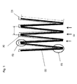
- Fig. 1 shows a section of a typical filter system in the form of a fine filter according to the prior art.
- a filter layer 1 is folded and thus forms a total of eight filter layers 2 - more precisely filter pleated layers 2 - which have a pleat width B.
- the stream S of the medium to be filtered is indicated by the arrows.
- On the downstream side of the filter layers 2 is a support grid 3, on which rest the filter layers 2 and which supports the filter layers 2 in pressure action.
- the filter fold spacing A shows the distance between two filter layers 2 or Filterfalterlagen 2 on.
- the highest possible values for the filter characteristic (K) are sought.
- the thickness s of the support grid 3 can also lead to a significant obstruction of the flow path, moreover, prove stiff support grid 3 in the production of filter layers 2 in the form of bellows follower bellows as complicating.
- the filter characteristic (K) can therefore not exceed a certain, concept or execution-related limit in Stützblech- or support grid embodiments.
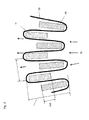
- Fig. 2 an inventive filter system is shown in the form of a fine filter. It should be noted that the same reference numerals in all figures refer to the same components, so it is disregarded that in each individual figure, all components are described again.
- a filter layer 1 is similar to Fig. 1 stripe-shaped to filter layers 2 folded. Instead of the individual filter layer 1, this may also consist of a composite of filter layers 1, if this is desired or advantageous for the filter performance.
- the filter layer 1 (or the composite of filter layers 1) could be formed endless, resulting in a cylindrical jacket-shaped configuration of the filter layers in the form of a bellows would result.
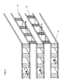
- Between the filter layers 2 are dimensionally stable porous body 7, 8 arranged in strip form, which ensure the mutual spacing of opposing filter layers 2. For an optimal filter effect, it is preferably provided that the dimensionally stable porous bodies 7, 8 have an overlapping area 14 at least in sections.
- a dimensionally stable porous body 7 is arranged offset in relation to another dimensionally stable porous body 8 and at least partially disposed over the entire area of the first dimensionally stable porous body 7.
- the cover 14 extends substantially parallel to or along the flow direction of the flow S.
- the stream S flows through both the filter layers 2 of the filter layer 1 and the dimensionally stable porous body 7, 8, wherein the dimensionally stable porous body 7, 8
- the orientation of the dimensionally stable porous body 7, 8 is selected so that it has the largest surface area in the Are arranged substantially parallel to or along the flow direction of the stream S.
- the filter fold width B can thus be very large and the filter fold spacing A can be selected to be very small, without the risk that the filter layers 2 come to bear under pressure or the distance between the filter layers 2 is unduly low.
- the design of the dimensionally stable porous body 7, 8 leaves both the geometry as well as the structure and the material many freedoms that can be advantageously used for special applications.
- the structure of the dimensionally stable porous body 7, 8 can be selected such that a prefilter effect is achieved and the surface load of the filter layer 1 is thereby reduced.
- This can e.g. be achieved in that the inflow-side dimensionally stable porous body 7, 8 has a special and advantageously variable porosity.
- an average porosity of the dimensionally stable porous body 7, 8 has proven to be greater than the mean porosity of the filter layer 1 by about 100-500%.
- the dimensionally stable porous bodies 7, 8 on the outflow side of the fine filter have, in contrast to the inflow-side dimensionally stable porous bodies 7, 8 primarily the function of keeping distance of the pleat surfaces or filter layers 2, so here is the most important selection criterion for the dimensionally stable porous body 7, 8 therein is to ensure a sufficiently high stiffness with minimal pressure loss.
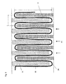
- Fig. 3 is an embodiment of a filter system according to the invention based on strip-shaped or plate-shaped dimensionally stable porous bodies 7, 8 shown. It can be seen that in this way very wide folds (large filter fold width B) and thus very large filter surfaces in a small space can be realized.
- the proposed method allows an extremely stable, mutual support of the filter layers 2 of the bellows.
- filter systems designed in this manner are also suitable for cleaning by backwashing when the filtrate is solids.
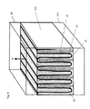
- Fig. 4 is a possible embodiment of the example of Fig. 3 exemplified.
- a planar filter arrangement is shown in a cuboid filter box.
- the flow of the filter layers 2 of the filter layer 1 is carried out conveniently perpendicular to the fold edges 6.
- the front side of the filter box is closed, for example by (not shown) casting compounds. It is already visually obvious that a maximum filter area can be accommodated within the housing volume.
- Fig. 5 discloses a preferred embodiment of a filter system in the form of a fine filter.
- the support elements consist of dimensionally stable porous bodies 7, 8 for flat filter layers 2 in, for example, box-shaped filter design.
- the support elements consist here of strips of dimensionally stable porous bodies 7, 8, which are placed crosswise to the filter layers 2 of the adjacent planes and which are spaced apart.
- the flow directions of the material flow within the filter planes are different for inflowing and outflowing regions, wherein the angle between the flow directions is preferably greater than 30 °.
- the flow losses can be further reduced in this way, as well as the required amount of dimensionally stable porous bodies 7, 8. Thereby, the efficiency of the proposed solution method can be further increased or the production costs are reduced.
- FIG. 6 an exemplary filter system based on the present proposed solution is shown, wherein the box-shaped fine filter area 13 in which the fine filter layers 2 and fine filter layers 1 are stacked flat preceded by a pre-filter 12 whose fiber filaments are packed less densely than in the fine filter layers 1 and where therefore only larger particles are deposited with higher efficiency.
- a plurality of filter layers 1 are arranged parallel to filter layers 2 and also aligned parallel to the lateral housing walls 15 and perpendicular to the upper housing wall 16.
- the pre-filter 12 is housed in or at the end of the inlet box 11. Through this, the material flow to be filtered is performed before it is passed with correspondingly lower filtrate load on the fold edges 6 of the fine filter pack.
Landscapes
- Chemical & Material Sciences (AREA)
- Chemical Kinetics & Catalysis (AREA)
- Filtering Materials (AREA)
- Filtering Of Dispersed Particles In Gases (AREA)
Applications Claiming Priority (1)
| Application Number | Priority Date | Filing Date | Title |
|---|---|---|---|
| AT1082012A AT511606B1 (de) | 2012-01-27 | 2012-01-27 | Filtersystem |
Publications (2)
| Publication Number | Publication Date |
|---|---|
| EP2620204A2 true EP2620204A2 (fr) | 2013-07-31 |
| EP2620204A3 EP2620204A3 (fr) | 2013-08-28 |
Family
ID=47623946
Family Applications (1)
| Application Number | Title | Priority Date | Filing Date |
|---|---|---|---|
| EP13152650.1A Withdrawn EP2620204A3 (fr) | 2012-01-27 | 2013-01-25 | Système de filtre |
Country Status (2)
| Country | Link |
|---|---|
| EP (1) | EP2620204A3 (fr) |
| AT (1) | AT511606B1 (fr) |
Family Cites Families (8)
| Publication number | Priority date | Publication date | Assignee | Title |
|---|---|---|---|---|
| DE1761318A1 (de) * | 1968-05-03 | 1972-03-23 | Delbag Luftfilter Gmbh | Abstandshalter fuer Filterpacks |
| DE3150392A1 (de) * | 1981-12-16 | 1983-06-23 | Delbag-Luftfilter Gmbh, 1000 Berlin | Kompaktes universal-grossflaechenfiltersystem nach dembaukastenprinzip zur luftreinigung |
| DE4115404A1 (de) * | 1991-05-10 | 1992-11-12 | Mgf Gutsche & Co Gmbh Betriebs | Verfahren zum herstellen eines filtermediums und danach hergestelltes filtermedium |
| DE19931307B4 (de) * | 1999-07-07 | 2006-06-14 | Daimlerchrysler Ag | Vorrichtung zum Filtern eines Rußpartikel transportierenden Abgases |
| DE10349352B3 (de) * | 2003-10-19 | 2005-01-13 | Trippe, Gustav, Dr. | Reinigungsaggregat für Abgase aus Brennkraftmaschinen |
| DE102004001717A1 (de) * | 2004-01-13 | 2005-08-04 | Robert Bosch Gmbh | Filtereinrichtung, insbesondere für ein Abgassystem einer Brennkraftmaschine |
| DE102005054273A1 (de) * | 2005-11-11 | 2007-05-16 | Freudenberg Carl Kg | Filterelement mit Ausnehmungs- und/oder Durchgangsbereichen |
| JP4634313B2 (ja) * | 2006-01-31 | 2011-02-16 | 三菱重工業株式会社 | ガス浄化装置 |
-
2012
- 2012-01-27 AT AT1082012A patent/AT511606B1/de not_active IP Right Cessation
-
2013
- 2013-01-25 EP EP13152650.1A patent/EP2620204A3/fr not_active Withdrawn
Also Published As
| Publication number | Publication date |
|---|---|
| AT511606A4 (de) | 2013-01-15 |
| AT511606B1 (de) | 2013-01-15 |
| EP2620204A3 (fr) | 2013-08-28 |
Similar Documents
| Publication | Publication Date | Title |
|---|---|---|
| DE102004000050B4 (de) | Filterelement, insbesondere Innenraumfilter, zur stirnseitigen Anströmung | |
| DE102008020478B4 (de) | Filtermodul und Filtereinheit | |
| EP2387446B1 (fr) | Filtre combiné | |
| DE102015002672A1 (de) | Filtermedium und Filterelement mit einem Filtermedium | |
| DE102010045500A1 (de) | Filterflächenteil | |
| EP2700438B1 (fr) | Dispositif de filtre | |
| EP3129118B1 (fr) | Dispositif de filtration | |
| EP0045516B1 (fr) | Insertion de filtre pour filtre d'adsorption de gaz, en particulier pour la purification de l'air | |
| DE2444224C3 (de) | Trennvorrichtung | |
| DE2256489A1 (de) | Filterbeutel | |
| DE69206891T2 (de) | Filter | |
| EP3698861A1 (fr) | Dispositif filtrant | |
| DE10020108C2 (de) | Mehrstufige Filteranlage | |
| AT511606B1 (de) | Filtersystem | |
| DE69103022T2 (de) | Filter. | |
| DE102014008699B4 (de) | Filterelement mit prismatischer Grundform und Filter | |
| WO2017137335A1 (fr) | Corps de milieu séparateur destiné à être utilisé dans un séparateur | |
| DE10102100A1 (de) | Filterelement mit zick-zack-förmig ausgebildetem Filtermaterial | |
| AT512535B1 (de) | Filtereinrichtung | |
| AT512190B1 (de) | Vorrichtung zur abscheidung von stoffen | |
| DE102016106699A1 (de) | Filterelement | |
| EP4520423B1 (fr) | Module de filtration | |
| DE10044579A1 (de) | Rohrförmiges Filterelement | |
| EP3750614A1 (fr) | Filtre à tôles de séparation à contre-plis | |
| DE102024108406A1 (de) | Oversprayfiltermedium |
Legal Events
| Date | Code | Title | Description |
|---|---|---|---|
| PUAL | Search report despatched |
Free format text: ORIGINAL CODE: 0009013 |
|
| PUAI | Public reference made under article 153(3) epc to a published international application that has entered the european phase |
Free format text: ORIGINAL CODE: 0009012 |
|
| AK | Designated contracting states |
Kind code of ref document: A2 Designated state(s): AL AT BE BG CH CY CZ DE DK EE ES FI FR GB GR HR HU IE IS IT LI LT LU LV MC MK MT NL NO PL PT RO RS SE SI SK SM TR |
|
| AX | Request for extension of the european patent |
Extension state: BA ME |
|
| AK | Designated contracting states |
Kind code of ref document: A3 Designated state(s): AL AT BE BG CH CY CZ DE DK EE ES FI FR GB GR HR HU IE IS IT LI LT LU LV MC MK MT NL NO PL PT RO RS SE SI SK SM TR |
|
| AX | Request for extension of the european patent |
Extension state: BA ME |
|
| RIC1 | Information provided on ipc code assigned before grant |
Ipc: B01D 46/52 20060101AFI20130724BHEP |
|
| 17P | Request for examination filed |
Effective date: 20140228 |
|
| RBV | Designated contracting states (corrected) |
Designated state(s): AL AT BE BG CH CY CZ DE DK EE ES FI FR GB GR HR HU IE IS IT LI LT LU LV MC MK MT NL NO PL PT RO RS SE SI SK SM TR |
|
| 17Q | First examination report despatched |
Effective date: 20151207 |
|
| STAA | Information on the status of an ep patent application or granted ep patent |
Free format text: STATUS: THE APPLICATION IS DEEMED TO BE WITHDRAWN |
|
| 18D | Application deemed to be withdrawn |
Effective date: 20160618 |