EP2620236A2 - Lingotière de passage pour la coulée d'une barre, notamment avec profilés de blooms ou de billettes - Google Patents
Lingotière de passage pour la coulée d'une barre, notamment avec profilés de blooms ou de billettes Download PDFInfo
- Publication number
- EP2620236A2 EP2620236A2 EP12196675.8A EP12196675A EP2620236A2 EP 2620236 A2 EP2620236 A2 EP 2620236A2 EP 12196675 A EP12196675 A EP 12196675A EP 2620236 A2 EP2620236 A2 EP 2620236A2
- Authority
- EP
- European Patent Office
- Prior art keywords
- inner tube
- continuous casting
- casting mold
- sleeve
- cooling
- Prior art date
- Legal status (The legal status is an assumption and is not a legal conclusion. Google has not performed a legal analysis and makes no representation as to the accuracy of the status listed.)
- Withdrawn
Links
- 238000009749 continuous casting Methods 0.000 title claims abstract description 48
- 238000001816 cooling Methods 0.000 claims abstract description 77
- 239000012809 cooling fluid Substances 0.000 claims abstract description 20
- 238000005304 joining Methods 0.000 claims abstract description 6
- 230000005499 meniscus Effects 0.000 claims abstract description 5
- 229910000831 Steel Inorganic materials 0.000 claims description 6
- 239000010959 steel Substances 0.000 claims description 6
- RYGMFSIKBFXOCR-UHFFFAOYSA-N Copper Chemical compound [Cu] RYGMFSIKBFXOCR-UHFFFAOYSA-N 0.000 claims description 4
- 229910052802 copper Inorganic materials 0.000 claims description 4
- 239000010949 copper Substances 0.000 claims description 4
- 239000007788 liquid Substances 0.000 claims description 4
- 229910000881 Cu alloy Inorganic materials 0.000 claims description 2
- 239000002184 metal Substances 0.000 claims description 2
- 229910052751 metal Inorganic materials 0.000 claims description 2
- 239000012530 fluid Substances 0.000 abstract description 5
- 229910001338 liquidmetal Inorganic materials 0.000 abstract 1
- XLYOFNOQVPJJNP-UHFFFAOYSA-N water Substances O XLYOFNOQVPJJNP-UHFFFAOYSA-N 0.000 description 10
- 238000005266 casting Methods 0.000 description 9
- 238000009826 distribution Methods 0.000 description 7
- 238000004026 adhesive bonding Methods 0.000 description 3
- 230000008901 benefit Effects 0.000 description 3
- 239000000498 cooling water Substances 0.000 description 3
- 238000005476 soldering Methods 0.000 description 3
- 238000003466 welding Methods 0.000 description 3
- 230000010355 oscillation Effects 0.000 description 2
- 239000011195 cermet Substances 0.000 description 1
- 230000008859 change Effects 0.000 description 1
- 239000011248 coating agent Substances 0.000 description 1
- 238000000576 coating method Methods 0.000 description 1
- 239000002131 composite material Substances 0.000 description 1
- 230000000694 effects Effects 0.000 description 1
- 230000017525 heat dissipation Effects 0.000 description 1
- 238000009434 installation Methods 0.000 description 1
- 238000012423 maintenance Methods 0.000 description 1
- 238000004519 manufacturing process Methods 0.000 description 1
- 239000000463 material Substances 0.000 description 1
- 239000000155 melt Substances 0.000 description 1
- 238000003801 milling Methods 0.000 description 1
- 230000004048 modification Effects 0.000 description 1
- 238000012986 modification Methods 0.000 description 1
- 230000009467 reduction Effects 0.000 description 1
- 230000007704 transition Effects 0.000 description 1
Images




Classifications
-
- B—PERFORMING OPERATIONS; TRANSPORTING
- B22—CASTING; POWDER METALLURGY
- B22D—CASTING OF METALS; CASTING OF OTHER SUBSTANCES BY THE SAME PROCESSES OR DEVICES
- B22D11/00—Continuous casting of metals, i.e. casting in indefinite lengths
- B22D11/04—Continuous casting of metals, i.e. casting in indefinite lengths into open-ended moulds
- B22D11/055—Cooling the moulds
-
- B—PERFORMING OPERATIONS; TRANSPORTING
- B22—CASTING; POWDER METALLURGY
- B22D—CASTING OF METALS; CASTING OF OTHER SUBSTANCES BY THE SAME PROCESSES OR DEVICES
- B22D11/00—Continuous casting of metals, i.e. casting in indefinite lengths
- B22D11/04—Continuous casting of metals, i.e. casting in indefinite lengths into open-ended moulds
- B22D11/041—Continuous casting of metals, i.e. casting in indefinite lengths into open-ended moulds for vertical casting
-
- B—PERFORMING OPERATIONS; TRANSPORTING
- B22—CASTING; POWDER METALLURGY
- B22D—CASTING OF METALS; CASTING OF OTHER SUBSTANCES BY THE SAME PROCESSES OR DEVICES
- B22D11/00—Continuous casting of metals, i.e. casting in indefinite lengths
- B22D11/04—Continuous casting of metals, i.e. casting in indefinite lengths into open-ended moulds
-
- B—PERFORMING OPERATIONS; TRANSPORTING
- B22—CASTING; POWDER METALLURGY
- B22D—CASTING OF METALS; CASTING OF OTHER SUBSTANCES BY THE SAME PROCESSES OR DEVICES
- B22D11/00—Continuous casting of metals, i.e. casting in indefinite lengths
- B22D11/04—Continuous casting of metals, i.e. casting in indefinite lengths into open-ended moulds
- B22D11/043—Curved moulds
Definitions
- From the GB 2 177 331 A is a continuous casting mold for a strand with billet or billet profile known, wherein the inner tube has a plurality of cooling slots in the longitudinal direction of the mold.
- the disadvantage of this is that the rigidity of the inner tube is reduced due to the cooling slots and the cooling fluid that can flow between the inner tube and the outer tube, the cooling slots flows through insufficiently.
- the desired effect of the cooling slots namely to increase the cooling performance of the mold by bringing the cooling fluid to the molten steel in the mold cavity, is achieved only to an insufficient degree.
- the font can not be removed.
- From the DE 10 2005 059 712 A1 is a continuous mold with an inner tube and a plurality of water baffles known.
- the inner tube has a plurality of cooling slots in the longitudinal direction of the mold, whereby the heat removal from the melt is increased. By the Wasserleitbleche a sufficient flow through the cooling slots is ensured.
- a disadvantage of this solution is that the rigidity of the structural unit, consisting of the slotted inner tube and the sleeve, is greatly reduced compared to an unslotted inner tube.
- the object of the invention is to overcome the disadvantages of the prior art and to provide a continuous casting mold, which allows a higher cooling capacity and in which the mold has a high rigidity.
- the cuff which completely encloses the inner tube in a normal plane to the longitudinal axis, and the cuff by joining (eg by gluing, soldering or Welding) is connected to the inner tube, the inner tube, so that the structural unit, consisting of the slotted inner tube and the sleeve, at least not significantly lower stiffness.
- the structural unit consisting of the slotted inner tube and the sleeve, at least not significantly lower stiffness.
- the casting speed can be increased, so that it is possible to further increase the casting speed in a continuous casting machine.
- the length of the cooling slots which is typically in the range of the meniscus of the liquid steel, preferably extends over 20% to 100% of the total length of the inner tube.
- the cuff is split, with one part of the cuff against another part of the cuff Cuff is formed braced.
- the clamping force for example via the biasing force or the tightening torque of a screw, which braces one part against another part of the sleeve, can be easily adjusted.
- the assembly or disassembly of the sleeve is simplified with the inner tube.
- the continuous casting mold on the lower end face has a connection for introducing the cooling fluid into the cooling jacket and on the upper end side has a connection for carrying out the cooling fluid from the cooling jacket.
- This embodiment has the advantage over lateral connections that the cooling fluid flows through the mold along the entire longitudinal extent.
- the inner tube Since the inner circumferential surface of the inner tube is exposed to high temperature loads and to increase the heat dissipation through the inner tube, it is advantageous if the inner tube of a copper alloy (optionally with a coating of a hard, high temperature resistant material, see, for example http: // en. wikipedia.org / wiki / cermet ).
- the cuff be detachable, e.g. is connected to the inner tube via at least one connecting element such as a screw connection.
- the inner tube it is of course also possible for the inner tube to be non-releasably connected to the cuff, e.g. by soldering, welding or gluing.
- the collar In order to redirect the flow of cooling fluid safely from the cooling jacket into the cooling slots, it is advantageous for the collar to be sealed on its outer circumferential surface (For example, a so-called O-ring). This prevents leakage of the cooling fluid between the sleeve and the outer tube.
- a split cuff it is advantageous to make the cuff split in a plane passing through the longitudinal axis of the inner tube.
- the continuous casting mold according to the invention is equally applicable to straight tube molds, i. when the inner tube and the outer tube have a straight longitudinal axis, as well as for curved tube molds, i. when the inner tube and the outer tube have a bent longitudinal axis.
- cooling slots it is advantageous if all the cooling slots in a normal plane to the longitudinal axis have a first flow-through surface, when the cooling jacket between the inner tube and the outer tube (ie outside the length range of the inner tube having cooling slots) in a normal plane to Longitudinal axis has a second through-flowable surface, wherein the first flow-through surface is between 50 and 200% of the second permeable surface.
- the hydraulic diameter of the cooling slots substantially equal to the hydraulic diameter of the cooling jacket.
- cooling slots not from the inner tube but from the sleeve.
- the advantage of this is that a smooth inner tube (without cooling slots) can be used. In general, however, it is easier to use the slots, e.g. by milling, to produce from the outer surface of the inner tube.
- the inner tube is preferably made in one piece.
- Such molds are referred to as tube molds.
- the inner tube is preferably formed from a plurality of copper cassette plates.
- the copper cassette plates are flat; often these are - e.g. in molds for thin slabs - curved.
- the meniscus is arranged in the longitudinal region (i.e., in the region of the inner tube with the cooling slots).
- Fig. 1 shows a perspective view of a continuous casting mold 1 according to the invention, which is suitable for the continuous casting of a strand with billet or billet profile of molten steel.
- straight molds were always shown, but the invention is by no means limited thereto and can be applied without restriction even with a bent mold.
- the continuous casting mold 1 has a straight inner tube 2, which has a mold cavity with a billet or pre-block profile which is open on both sides along the longitudinal axis 3.
- the cooling slots 5 in the inner tube 2 and the sleeve 7 are in Fig. 1 covered by the outer tube 8 so that they are not shown.
- the inner tube 2 is divided into its four quadrants, the dividing planes each extending through the longitudinal axis 3.
- the cuff 7 is off Fig. 1 and an undivided variant of the inner tube 2 is shown.
- the inner tube 2 has a plurality of cooling slots 5, which extend parallel to the longitudinal axis 3 over a longitudinal region 6 of the inner tube 2.
- the in Fig. 5 illustrated mold cavity 4 of the mold has a square cross-section of 130 x 130 mm.
- the cooling slots have a width of 10 mm and a depth of 8 mm to the bottom.
- the distance between two cooling slots 5 is 18 mm.
- the thickness of the inner tube is not constant over the longitudinal axis 3 and is between 13 and 15 mm; in the region of the cooling slots 5, the inner tube has a thickness of 13 mm, so that the minimum distance between the mold cavity and the cooling slot is about 5 mm.
- the illustrated sleeve 7 is constructed in one piece and has at the operating temperature he mold between the inner circumferential surface of the sleeve 7 and the outer surface of the inner tube 2 a press fit, so that the weakened by the cooling slots 5 inner tube 2 is supported on the sleeve 7.
- Fig. 3 shows the outer tube 8 of Fig. 1 in a separate presentation. As can be seen in the upper area, the outer tube 8 has a smooth inner circumferential surface.
- Fig. 4 shows an elevation view Fig. 2 .
- Fig. 5 shows an elevation and a floor plan to the continuous mold 1.
- Fig. 6 shows a first sectional view of the continuous mold 1 along the section line BB of Fig. 5 ,
- the inner tube 2 is formed of four quadrants.
- the cooling jacket since most of the cooling fluid water is used, also called water jacket.
- the streamable Surface between the inner tube 2 and the outer tube 8 is approximately 2700 mm 2 here .
- Fig. 7 is a section along the section line CC shown. It can be seen that, on the one hand, the sleeve 7 encloses the inner tube 2 with the cooling slots 5. On the other hand, the sleeve 7 is enclosed by the outer tube 8, so that these three components 2,7,8 mutually support.
- the cooling slots By performing the cooling slots with a semicircular base, excessive notch stresses in the inner tube 2 are avoided.
- the sum of the flow-through surfaces of the cooling slots 5 between the inner tube 2 and the outer tube 8 is approximately 2200 mm 2 here .
- the Fig. 8 shows a section along the section line DD of Fig. 5 .
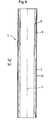
- FIG. 9 shows a longitudinal section along the section line EE of Fig. 7
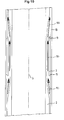
- a detail about this is in the FIG. 10 represents enlarged, from which it is apparent how the cooling fluid flows through the cooling jacket substantially from bottom to top, ie opposite to the casting direction which runs vertically from top to bottom.
- the cooling fluid extends vertically upwards until it is deflected by the sleeve 7 into the cooling slots 5.
- the cooling slots 5 In the longitudinal region of the inner tube 2, the cooling slots 5, the fluid flows again substantially vertically upwards, until it again after completion of the sleeve in the original cooling jacket between the inner tube 2 and outer tube 8 is deflected.
- the flow directions of the fluid are shown by arrows 10 in this figure.
- FIGS. 11 to 13 show a half of a machine head for a continuous casting machine for casting a billet or Vorblockstrangs comprising a cooled continuous casting mold 1 which is detachably connected to a lifting table 16, a stationary support structure 15 and an oscillation device for oscillating the lifting table 16 with the mold 1 relative to the support structure 15th ,
- the inner tube 2 of the continuous mold 1 has along at least 90% of the total length of the inner tube 2 cooling slots 5, so that the cooling capacity of the mold is increased due to the small wall thickness between the bottom of the cooling slots 5 and the liquid steel in the mold cavity 4.
- the inner tube 2 is connected at operating temperature of the mold 1 by a press or shrink fit with the sleeve 7.
- the inner tube 2, the sleeve 7, and the outer tube 8 with the water distribution spaces 11a, 11b form an insert (also "cartridge"), which can be easily and quickly replaced.
- the insert is connected to the lifting table 16, which is oscillatable relative to the support structure 15 via at least one articulation lever 14 with an oscillation drive, not shown (for example a hydraulic cylinder, an eccentric shaft, an electric linear drive, etc.).
- an oscillation drive for example a hydraulic cylinder, an eccentric shaft, an electric linear drive, etc.
- the flow direction of a cooling fluid is in FIG. 12 shown in more detail.
- the cooling fluid flows via a flexible connection (not shown) (eg a hose) from the stationary support structure 15 into the water distribution space 11a. From there, the fluid flows in the cooling jacket between the outer tube 8 and the sleeve 7 downwards (arrow 10) and is deflected at the lower end of the mold. After that flows through the cooling water in the cooling slots 5 between the inner tube 2 and the sleeve 7 against the extension direction of the strand upwards (see also Fig. 13 showing the arrangement of the inner tube 2, the sleeve 7 and the outer tube 8) and enters the water distribution chamber 11b at the upper end of the mold 1 after a further deflection. From there, the heated cooling water is discharged from the water distribution space 11b in a manner analogous to introduction into the water distribution space 11a.
- the exploded view in FIG. 14 shows that the above-mentioned insert 17, consisting of the inner tube 2, the sleeve 7, the outer tube 8 and the water distribution chambers 11a, 11b, can be easily removed during mold change or maintenance.
- the insert is removed upwards.
- After installation of a new insert 17 this is fixed with the flange 12 on the lifting table 16, so that the casting operation can be resumed after a short break.
- the inner tube 2 with the cooling slots 5 can be pressed out of the cuff in the workshop and a new inner tube 2 can be used.
Landscapes
- Engineering & Computer Science (AREA)
- Mechanical Engineering (AREA)
- Continuous Casting (AREA)
Applications Claiming Priority (1)
| Application Number | Priority Date | Filing Date | Title |
|---|---|---|---|
| ATA50014/2012A AT512433B1 (de) | 2012-01-30 | 2012-01-30 | Durchlaufkokille zum stranggiessen eines strangs mit knüppel- oder vorblockprofil |
Publications (2)
| Publication Number | Publication Date |
|---|---|
| EP2620236A2 true EP2620236A2 (fr) | 2013-07-31 |
| EP2620236A3 EP2620236A3 (fr) | 2017-07-19 |
Family
ID=47357991
Family Applications (1)
| Application Number | Title | Priority Date | Filing Date |
|---|---|---|---|
| EP12196675.8A Withdrawn EP2620236A3 (fr) | 2012-01-30 | 2012-12-12 | Lingotière de passage pour la coulée d'une barre, notamment avec profilés de blooms ou de billettes |
Country Status (3)
| Country | Link |
|---|---|
| EP (1) | EP2620236A3 (fr) |
| CN (1) | CN103223476B (fr) |
| AT (1) | AT512433B1 (fr) |
Cited By (2)
| Publication number | Priority date | Publication date | Assignee | Title |
|---|---|---|---|---|
| WO2016178153A1 (fr) * | 2015-05-05 | 2016-11-10 | Danieli & C. Officine Meccaniche S.P.A. | Lingotière pour la coulée continue |
| CN109604545A (zh) * | 2018-12-17 | 2019-04-12 | 阳春新钢铁有限责任公司 | 一种对角剖分式冷却水套 |
Families Citing this family (1)
| Publication number | Priority date | Publication date | Assignee | Title |
|---|---|---|---|---|
| CN109093084B (zh) * | 2018-09-29 | 2020-03-31 | 东北大学 | 一种连铸薄板坯的生产方法 |
Family Cites Families (13)
| Publication number | Priority date | Publication date | Assignee | Title |
|---|---|---|---|---|
| FR2423285A1 (fr) * | 1978-04-17 | 1979-11-16 | Siderurgie Fse Inst Rech | Chemise de refroidissement pour lingotiere de coulee continue des metaux |
| DE3411359A1 (de) * | 1984-03-28 | 1985-10-31 | Mannesmann AG, 4000 Düsseldorf | Stranggiesskokille fuer rund- bzw. knueppelquerschnitte, insbesondere fuer das vergiessen von fluessigem stahl |
| FI852493L (fi) * | 1985-06-24 | 1986-12-25 | Outokumpu Oy | Kokill. |
| CH685432A5 (de) * | 1992-06-11 | 1995-07-14 | Concast Standard Ag | Kokille zum Stranggiessen von Metall, insbesondere von Stahl in Knüppel- und Vorblockquerschnitte. |
| LU88393A1 (fr) * | 1993-08-20 | 1995-03-01 | Wurth Paul Sa | Lingotière de coulée continue |
| US5771958A (en) * | 1995-09-14 | 1998-06-30 | Ag Industries, Inc. | Mold for continuous casting system |
| DE19859040A1 (de) * | 1998-12-21 | 2000-06-29 | Km Europa Metal Ag | Kokillenrohr und Verfahren zum Rekalibrieren eines Kokillenrohrs |
| JP3930761B2 (ja) * | 2002-04-17 | 2007-06-13 | 株式会社神戸製鋼所 | チューブ方式連続鋳造用鋳型 |
| JP4202718B2 (ja) * | 2002-10-28 | 2008-12-24 | 株式会社神戸製鋼所 | 溶融金属の連続鋳造用高周波電磁界鋳造鋳型 |
| EP1468760B1 (fr) * | 2003-04-16 | 2005-05-25 | Concast Ag | Lingotière tubalaire pour la coulée continue |
| DE102006001812A1 (de) * | 2005-12-05 | 2007-06-06 | Km Europa Metal Ag | Kokille zum Stranggießen von Metall |
| DE102005059712A1 (de) * | 2005-12-12 | 2007-06-21 | Km Europa Metal Ag | Kokille |
| PL2014393T3 (pl) * | 2007-06-04 | 2012-09-28 | Concast Ag | Krystalizator do ciągłego odlewania kęsisk kwadratowych, kęsisk płaskich lub kęsów |
-
2012
- 2012-01-30 AT ATA50014/2012A patent/AT512433B1/de not_active IP Right Cessation
- 2012-12-12 EP EP12196675.8A patent/EP2620236A3/fr not_active Withdrawn
-
2013
- 2013-01-30 CN CN201310035431.7A patent/CN103223476B/zh not_active Expired - Fee Related
Non-Patent Citations (1)
| Title |
|---|
| None * |
Cited By (2)
| Publication number | Priority date | Publication date | Assignee | Title |
|---|---|---|---|---|
| WO2016178153A1 (fr) * | 2015-05-05 | 2016-11-10 | Danieli & C. Officine Meccaniche S.P.A. | Lingotière pour la coulée continue |
| CN109604545A (zh) * | 2018-12-17 | 2019-04-12 | 阳春新钢铁有限责任公司 | 一种对角剖分式冷却水套 |
Also Published As
| Publication number | Publication date |
|---|---|
| CN103223476B (zh) | 2016-03-02 |
| EP2620236A3 (fr) | 2017-07-19 |
| AT512433B1 (de) | 2017-08-15 |
| CN103223476A (zh) | 2013-07-31 |
| AT512433A1 (de) | 2013-08-15 |
Similar Documents
| Publication | Publication Date | Title |
|---|---|---|
| EP2014393B1 (fr) | Lingotière destinée à la coulée de blooms, de brames ou de billettes | |
| DE19834289B4 (de) | Doppelwalzengießen | |
| DE102012215018A1 (de) | Gehäuse für eine elektrische Maschine mit mäanderförmigem Kühlkanal und Leitgeometrien | |
| EP2479875B1 (fr) | Boîtier à liquide refroidi doté d'une flasque pour machine électrique | |
| DE1458123B1 (de) | Verfahren zum kontinuierlichen Herstellen von mehreren profilierten Strängen und Anlage zur Durchführung dieses Verfahrens | |
| DE2914385C2 (fr) | ||
| WO2011066981A2 (fr) | Corps coulé à double paroi pour un moteur électrique refroidi par liquide | |
| DE10160135A1 (de) | Kokillenrohr zum Stranggießen von Metallen | |
| EP2620236A2 (fr) | Lingotière de passage pour la coulée d'une barre, notamment avec profilés de blooms ou de billettes | |
| DE19541049A1 (de) | Gießwalze | |
| AT517139B1 (de) | Gestützte Rohrkokille für Knüppel- und Vorblockanlagen | |
| DE102013010460B4 (de) | Vorrichtung zur Einflussnahme auf den Abströmbereich einer Rohrträgerplatte eines Rohrbündel-Wärmeaustauschers | |
| EP2900401B1 (fr) | Rouleau de guidage de barres refroidi, à plusieurs paliers | |
| CH685332A5 (de) | Stranggiesskokille. | |
| DE2717558C2 (fr) | ||
| WO2020025358A1 (fr) | Refroidissement d'une machine électrique | |
| EP1795281B1 (fr) | Lingotière pour coulée continue | |
| EP3130414B1 (fr) | Installation metallurgique de fusion, comprenant une lingotiere | |
| DE2616487A1 (de) | Verfahren und vorrichtung zum kontinuierlichen giessen eines stahlstranges in form einer rechteckfoermigen bramme | |
| EP1685916B1 (fr) | Panneau d'interconnexion | |
| AT405253B (de) | Stranggiesskokille | |
| DE2828895A1 (de) | Metallurgischer behaelter | |
| WO2011095193A1 (fr) | Dispositif d'injection de gaz | |
| AT522037B1 (de) | Kokilleneinheit zum Stranggießen von Metallprodukten sowie Stranggießanlage | |
| EP4686515A1 (fr) | Lingotière pour installation de coulée continue et installation de coulée continue |
Legal Events
| Date | Code | Title | Description |
|---|---|---|---|
| PUAI | Public reference made under article 153(3) epc to a published international application that has entered the european phase |
Free format text: ORIGINAL CODE: 0009012 |
|
| AK | Designated contracting states |
Kind code of ref document: A2 Designated state(s): AL AT BE BG CH CY CZ DE DK EE ES FI FR GB GR HR HU IE IS IT LI LT LU LV MC MK MT NL NO PL PT RO RS SE SI SK SM TR |
|
| AX | Request for extension of the european patent |
Extension state: BA ME |
|
| RAP1 | Party data changed (applicant data changed or rights of an application transferred) |
Owner name: PRIMETALS TECHNOLOGIES AUSTRIA GMBH |
|
| PUAL | Search report despatched |
Free format text: ORIGINAL CODE: 0009013 |
|
| AK | Designated contracting states |
Kind code of ref document: A3 Designated state(s): AL AT BE BG CH CY CZ DE DK EE ES FI FR GB GR HR HU IE IS IT LI LT LU LV MC MK MT NL NO PL PT RO RS SE SI SK SM TR |
|
| AX | Request for extension of the european patent |
Extension state: BA ME |
|
| RIC1 | Information provided on ipc code assigned before grant |
Ipc: B22D 11/041 20060101AFI20170609BHEP Ipc: B22D 11/055 20060101ALI20170609BHEP Ipc: B22D 11/043 20060101ALI20170609BHEP |
|
| STAA | Information on the status of an ep patent application or granted ep patent |
Free format text: STATUS: REQUEST FOR EXAMINATION WAS MADE |
|
| 17P | Request for examination filed |
Effective date: 20180119 |
|
| RBV | Designated contracting states (corrected) |
Designated state(s): AL AT BE BG CH CY CZ DE DK EE ES FI FR GB GR HR HU IE IS IT LI LT LU LV MC MK MT NL NO PL PT RO RS SE SI SK SM TR |
|
| STAA | Information on the status of an ep patent application or granted ep patent |
Free format text: STATUS: EXAMINATION IS IN PROGRESS |
|
| 17Q | First examination report despatched |
Effective date: 20180507 |
|
| GRAP | Despatch of communication of intention to grant a patent |
Free format text: ORIGINAL CODE: EPIDOSNIGR1 |
|
| STAA | Information on the status of an ep patent application or granted ep patent |
Free format text: STATUS: GRANT OF PATENT IS INTENDED |
|
| INTG | Intention to grant announced |
Effective date: 20201221 |
|
| STAA | Information on the status of an ep patent application or granted ep patent |
Free format text: STATUS: THE APPLICATION IS DEEMED TO BE WITHDRAWN |
|
| 18D | Application deemed to be withdrawn |
Effective date: 20210501 |