EP2620380A1 - Récipient repliable avec une porte - Google Patents
Récipient repliable avec une porte Download PDFInfo
- Publication number
- EP2620380A1 EP2620380A1 EP13152902.6A EP13152902A EP2620380A1 EP 2620380 A1 EP2620380 A1 EP 2620380A1 EP 13152902 A EP13152902 A EP 13152902A EP 2620380 A1 EP2620380 A1 EP 2620380A1
- Authority
- EP
- European Patent Office
- Prior art keywords
- door
- wall
- collapsible container
- opening
- base
- Prior art date
- Legal status (The legal status is an assumption and is not a legal conclusion. Google has not performed a legal analysis and makes no representation as to the accuracy of the status listed.)
- Withdrawn
Links
- 238000009423 ventilation Methods 0.000 description 3
- 241000220223 Fragaria Species 0.000 description 2
- 238000007689 inspection Methods 0.000 description 2
- 235000021012 strawberries Nutrition 0.000 description 2
- 239000000853 adhesive Substances 0.000 description 1
- 230000001070 adhesive effect Effects 0.000 description 1
- 235000021022 fresh fruits Nutrition 0.000 description 1
- 230000002787 reinforcement Effects 0.000 description 1
- 230000000717 retained effect Effects 0.000 description 1
- 238000003466 welding Methods 0.000 description 1
Images
























Classifications
-
- B—PERFORMING OPERATIONS; TRANSPORTING
- B65—CONVEYING; PACKING; STORING; HANDLING THIN OR FILAMENTARY MATERIAL
- B65D—CONTAINERS FOR STORAGE OR TRANSPORT OF ARTICLES OR MATERIALS, e.g. BAGS, BARRELS, BOTTLES, BOXES, CANS, CARTONS, CRATES, DRUMS, JARS, TANKS, HOPPERS, FORWARDING CONTAINERS; ACCESSORIES, CLOSURES, OR FITTINGS THEREFOR; PACKAGING ELEMENTS; PACKAGES
- B65D21/00—Nestable, stackable or joinable containers; Containers of variable capacity
- B65D21/02—Containers specially shaped, or provided with fittings or attachments, to facilitate nesting, stacking, or joining together
- B65D21/0209—Containers specially shaped, or provided with fittings or attachments, to facilitate nesting, stacking, or joining together stackable or joined together one-upon-the-other in the upright or upside-down position
-
- B—PERFORMING OPERATIONS; TRANSPORTING
- B65—CONVEYING; PACKING; STORING; HANDLING THIN OR FILAMENTARY MATERIAL
- B65D—CONTAINERS FOR STORAGE OR TRANSPORT OF ARTICLES OR MATERIALS, e.g. BAGS, BARRELS, BOTTLES, BOXES, CANS, CARTONS, CRATES, DRUMS, JARS, TANKS, HOPPERS, FORWARDING CONTAINERS; ACCESSORIES, CLOSURES, OR FITTINGS THEREFOR; PACKAGING ELEMENTS; PACKAGES
- B65D11/00—Containers having bodies formed by interconnecting or uniting two or more rigid, or substantially rigid, components made wholly or mainly of plastics material
- B65D11/18—Containers having bodies formed by interconnecting or uniting two or more rigid, or substantially rigid, components made wholly or mainly of plastics material collapsible, i.e. with walls hinged together or detachably connected
- B65D11/1833—Containers having bodies formed by interconnecting or uniting two or more rigid, or substantially rigid, components made wholly or mainly of plastics material collapsible, i.e. with walls hinged together or detachably connected whereby all side walls are hingedly connected to the base panel
-
- B—PERFORMING OPERATIONS; TRANSPORTING
- B65—CONVEYING; PACKING; STORING; HANDLING THIN OR FILAMENTARY MATERIAL
- B65D—CONTAINERS FOR STORAGE OR TRANSPORT OF ARTICLES OR MATERIALS, e.g. BAGS, BARRELS, BOTTLES, BOXES, CANS, CARTONS, CRATES, DRUMS, JARS, TANKS, HOPPERS, FORWARDING CONTAINERS; ACCESSORIES, CLOSURES, OR FITTINGS THEREFOR; PACKAGING ELEMENTS; PACKAGES
- B65D11/00—Containers having bodies formed by interconnecting or uniting two or more rigid, or substantially rigid, components made wholly or mainly of plastics material
- B65D11/20—Details of walls made of plastics material
-
- B—PERFORMING OPERATIONS; TRANSPORTING
- B65—CONVEYING; PACKING; STORING; HANDLING THIN OR FILAMENTARY MATERIAL
- B65D—CONTAINERS FOR STORAGE OR TRANSPORT OF ARTICLES OR MATERIALS, e.g. BAGS, BARRELS, BOTTLES, BOXES, CANS, CARTONS, CRATES, DRUMS, JARS, TANKS, HOPPERS, FORWARDING CONTAINERS; ACCESSORIES, CLOSURES, OR FITTINGS THEREFOR; PACKAGING ELEMENTS; PACKAGES
- B65D21/00—Nestable, stackable or joinable containers; Containers of variable capacity
- B65D21/02—Containers specially shaped, or provided with fittings or attachments, to facilitate nesting, stacking, or joining together
- B65D21/0209—Containers specially shaped, or provided with fittings or attachments, to facilitate nesting, stacking, or joining together stackable or joined together one-upon-the-other in the upright or upside-down position
- B65D21/0212—Containers presenting local stacking elements protruding from the upper or lower edge of a side wall, e.g. handles, lugs, ribs, grooves
-
- B—PERFORMING OPERATIONS; TRANSPORTING
- B65—CONVEYING; PACKING; STORING; HANDLING THIN OR FILAMENTARY MATERIAL
- B65D—CONTAINERS FOR STORAGE OR TRANSPORT OF ARTICLES OR MATERIALS, e.g. BAGS, BARRELS, BOTTLES, BOXES, CANS, CARTONS, CRATES, DRUMS, JARS, TANKS, HOPPERS, FORWARDING CONTAINERS; ACCESSORIES, CLOSURES, OR FITTINGS THEREFOR; PACKAGING ELEMENTS; PACKAGES
- B65D25/00—Details of other kinds or types of rigid or semi-rigid containers
- B65D25/005—Side walls formed with an aperture or a movable portion arranged to allow removal or insertion of contents
-
- B—PERFORMING OPERATIONS; TRANSPORTING
- B65—CONVEYING; PACKING; STORING; HANDLING THIN OR FILAMENTARY MATERIAL
- B65D—CONTAINERS FOR STORAGE OR TRANSPORT OF ARTICLES OR MATERIALS, e.g. BAGS, BARRELS, BOTTLES, BOXES, CANS, CARTONS, CRATES, DRUMS, JARS, TANKS, HOPPERS, FORWARDING CONTAINERS; ACCESSORIES, CLOSURES, OR FITTINGS THEREFOR; PACKAGING ELEMENTS; PACKAGES
- B65D25/00—Details of other kinds or types of rigid or semi-rigid containers
- B65D25/28—Handles
- B65D25/30—Hand holes
Definitions
- the present invention relates generally to a collapsible crate and more particularly to a collapsible crate providing access to the interior when the crate is stacked.
- Fresh produce such as strawberries, is sometimes shipped in corrugated cardboard boxes.
- the produce may be shipped in plastic clamshell containers, a plurality of which are placed in each cardboard box. The boxes are then stacked for shipping.
- the boxes may be randomly inspected by cutting a hole in a wall of the one of the boxes so that one or more of the plastic clamshell containers can be removed for inspection of the produce.
- the inspection is not limited to the boxes at the top of the stack.
- the inspector may randomly cut a hole in the side of a box anywhere in the stack.
- a container includes a base and a plurality of walls.
- a first wall includes an opening therethrough.
- a first door selectively covers the opening through the first wall.
- the first door is slidable between an open, retracted position away from the opening and a closed position covering the opening.
- the door is pivotably connected to the side wall.
- the container is a collapsible container, such that the walls are pivotable between an upright position and a collapsed position on the base.
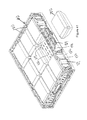
- FIG. 1 shows a crate 10 according to one embodiment of the present invention.
- the crate 10 includes a base 12, front wall 14, rear wall 15 and end walls 16.
- the base 12 includes an upper panel 18 having ventilation openings therethrough, side hinge members 20 to which the front and rear walls 14, 15 are hingeably connected and end upstanding portions 22 to which the end walls 16 are hingeably connected.
- the front wall 14 includes a pair of slidable doors 24, 25 to facilitate access to the interior of the crate 10 when other crates 10 (not shown) are stacked thereon.
- the front wall 14 includes outer wall portions 26 with a rail portion 34 therebetween defining an opening therebelow.
- the doors 24, 25 are slidably mounted in the opening below the rail portion 34.
- Handle openings 36 are formed through the doors 24, 25 to facilitate opening and closing the doors 24, 25.
- Teeth 38 may be formed at lower edges of the doors 24, 25 to discourage use of the doors 24, 25 as handles for lifting the crate 10.
- a downwardly sloped portion 28 of the base 12 is positioned below the doors 24, 25.
- an exterior surface of the front wall 14 includes a recess 40 adjacent a projecting portion 42.
- the interior surface of the end wall 16 includes a projecting portion 44 adjacent a recess 46 and a latch 48. These are aligned such that the projecting portion 44 and latch 48 of the end wall 16 will be received in the recess 40 on the front wall 14 and such that the projecting portion 42 will be received in the recess 46 of the end wall 16, as shown in Figure 3 .
- the crate 10 can be collapsed for efficient shipping and storage when empty.
- the front wall 14 and rear wall 15 are pivoted onto the base 12, and the end walls 16 are pivoted onto the front wall 14 and rear wall 15.
- the doors 24, 25 on the front wall 14 can be open or closed in the collapsed position.
- Figure 5 shows the crate 10 in the use position with the walls in the upright assembled position.
- the doors 24, 25 are open, i.e. they are slid away from one another adjacent the outer wall portions 26 of the front wall 14. This provides the opening below the rail 34 through which the interior of the crate 10 can be accessed.
- the downwardly sloped portion 28 of the base 12 partially defines the opening below the rail 34.
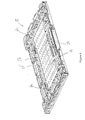
- Figure 6 is an exterior perspective view of the front wall 14 with the doors 24, 25 closed.
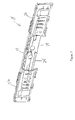
- Figure 7 is an interior perspective view of the front wall 14 of Figure 6 .
- Figure 8 is an exploded exterior perspective view of the front wall 14 and Figure 9 is the interior perspective view of Figure 8 .
- the front wall 14 includes the outer wall portions 26 integrally molded as a single piece of plastic with the rail portion 34 therebetween defining an opening therebelow.
- Outer covers 50 each include an attachment portion 52 and a cover portion 54.
- the cover portions 54 are between the attachment portions 52 and offset toward the exterior relative to the attachment portions 52.
- a post 56 projects rearwardly from each cover portion 54.
- Each door 24, 25 includes a lower portion 58 from which the teeth 38 descend.
- Each door 24, 25 includes a middle slot 60 above the lower portion 58 opening outward (i.e. away from the other door).
- An upper portion 62 extends above each middle slot 60 and is connected to the lower portion 58 by portions surrounding the handle openings 36.
- Alternating teeth 64 project upward from the upper portion 62.
- Latch members 66 protrude from the inner edges of the doors 24, 25.
- Each outer wall portion 26 includes an interlocking ridge portion 68, 70, respectively, protruding toward the exterior.
- attachment portions 52 and the posts 56 provide attachment surfaces for connecting the outer covers 50 to the outer wall portions 26, such as by vibration welding, adhesive, etc.
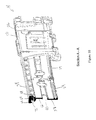
- Figure 10 is a section view taken along line A-A of Figure 6 , through door 24.
- the rail 34 includes a downwardly projecting T-shaped rail portion 72.
- the teeth 64 of the door 24 project upward and then inward toward one another, such that they interlock with the T-shaped rail portion 72. This retains the door 24, especially as it slides to the closed position.
- the lower portion 58 of the door 24 is offset toward the interior relative to the upper portion 62.
- Figure 11 is a section view taken along line B-B of Figure 6 , through door 25.
- the teeth 64 of the door 25 project upward and then inward toward one another, such that they interlock with the T-shaped rail portion 72. This retains the door 25, especially as it slides to the closed position.
- the post 56 is received in the middle slot 60 of the door 25, so that the door 25 can slide open and closed.
- the lower portion 58 of the door 24 is offset toward the exterior relative to the upper portion 62.
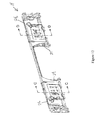
- Figure 12 is a perspective view of the front wall 14 with the doors 24, 25 in the open position, i.e. slid away from one another and substantially received between the outer wall portions 26 and the outer covers 50.
- Figure 13 is a section view taken along line C-C of Figure 12 , through the door 24.
- the post 56 is slidably received in the middle slot 60 of the door 24.
- the interlocking ridge 68 engages the upper portion 62 of the door 24 (which is offset toward the exterior).
- Figure 14 is a section view taken along line D-D of Figure 12 , through the door 25.
- the post 56 is slidably received in the middle slot 60 of the door 25.
- the interlocking ridge 70 engages the lower portion 58 of the door 25 (which is offset toward the exterior).
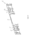
- Figure 15 is an exterior perspective view of the front wall 14 with the outer covers 50 removed and the doors 24, 25 closed.
- Figure 16 is an exterior perspective view of the front wall 14 with the outer covers 50 removed and the doors 24, 25 open. As is probably most apparent from Figures 15 and 16 , the doors 24, 25 move about an arc from the closed position ( Figure 15 ) down to the open position ( Figure 16 ).
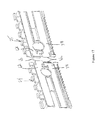
- Figure 17 is an enlarged exterior perspective view of the doors 24, 25 in a position close to engaging one another.
- the latches 66 are offset one another, because the upper portion 62 of the door 24 is offset toward the exterior, while the upper portion 62 of the door 25 is offset toward the interior.
- the lower portion 58 of the door 25 is offset toward the exterior while the lower portion 58 of the door 24 is offset toward the interior.
- the latches 66 include ribs projecting toward one another.
- the latches 66 can pass next to one another, with the ribs engaging one another to help keep the doors 24, 25 closed.
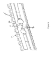
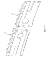
- Figure 19 is an interior perspective view corresponding to Figure 17 .
- Figure 20 is an interior perspective view corresponding to Figure 18 .
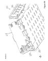
- Figure 21 is a perspective view of the crate 10 with a plurality of containers 100 stored therein.
- the containers 100 are retained in the crate 10 by the doors 24, 25.
- the side upstanding portion 20 includes an opening therethrough aligned with the sloped portion 28 of the base 12 and aligned with the opening in the front wall 14 between the outer wall portions 26.
- the doors 24, 25 can be slid away from each other into the outer wall portions 26.
- a container 100 can then be removed from the crate 10 through the opening in the front wall 14, as shown in Figures 23-24 .
- the remainder of the containers 100 can also be removed, one at a time, through the opening in the front wall 14.
- the sloped portion 28 of the base 12 helps fit the containers 100 below the rail 34.
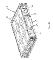
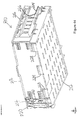
- a collapsible crate 110 according to a second embodiment is shown in Figures 29-41 .
- the crate 110 includes a base 112 to which side walls 114, 115 and end walls 116 are pivotably connected.
- the base 112 includes an upper panel 118 having ventilation openings therethrough, side upstanding portions 120 to which the side walls 114, 115 are hingeably connected and end upstanding portions 122 to which the end walls 116 are hingeably connected.
- the side wall 114 (the "front" wall) includes a door 124 that can be selectively opened to access the interior of the crate 110 through the side wall 114.
- a door 124 that can be selectively opened to access the interior of the crate 110 through the side wall 114.
- doors 124 could also be provided in the side wall 115 and/or end walls 116.
- the door 124 is positioned between outer wall portions 126 of the side wall 114.
- the outer wall portions 126 are connected by a rail 128 extending therebetween.
- the rail 128 defines an upper edge of the side wall 114.
- the door 124 is pivotably connected to the rail 128.
- Figure 30 is an exploded view of the side wall 114.
- the outer wall portions 126 are integrally molded as a single piece of plastic with the rail 128 and a support bar 134, which both extend between the outer wall portions 126.
- Hinge pins 130 are formed below each outer wall portion 126 for pivotably connecting to the side upstanding portions 120 of the base 112 ( Figure 29 ).
- An opening is defined between the outer wall portions 126.
- An interlocking portion 132 projects into the opening from each outer wall portion 126.
- the door 124 includes hinge members 136 that can snap-fit and pivotably connect to the rail 128.
- the door 124 further includes a handle portion 140 having outer tabs 142.
- the handle 140 and tabs 142 can be flexed relative to the remainder of the door 124, such that the tabs 142 can be selectively removed from interlocking with the interlocking portions 132 so that the door 124 can be opened.
- the side walls 114, 115 and end walls 116 can be pivoted to a collapsed position on the base 112 when the crate 110 is empty.
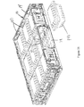
- Figure 32 shows the crate 110 loaded with a plurality of containers 180.
- the containers 180 are plastic "clam shell” containers 180, such as might contain fresh fruit, such as strawberries (the containers 180 would have many openings for ventilation).
- Figure 33 shows the crate 110 and containers 180 with the door 124 pivoted to an open position.
- the containers 180 can be removed from the crate 110 through the opening in the side wall 114.
- Figure 34 shows the side wall 114 with the door 124 in the closed position, with the tabs 142 snapped behind and interlocked with the interlocking portions 132 of the side wall 114.
- the door 124 has been partially opened, after releasing the tabs 142 from the interlocking portions 132, such as by lifting the handle 140.
- Other types of latches could be used instead of the tabs 142 and interlocking portions 132.
- the door 124 is pivoted to the open position, such that the container 180 can be removed from the crate 110 through the side wall 114.
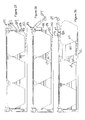
- Figures 37-39 are section views taken through the side wall 114, which correspond to Figures 34-36 , respectively.
- the base 112 includes the upper panel 118 upon which the containers 180 are supported.
- the upper panel 118 includes a sloped portion 148, which slopes downward within the base 112, leading to the door 124. As shown in Figures 39 and 39 , the sloped portion 148 provides sufficient clearance for the container 180 to be removed from the crate 110 below the rail 128.
- the base 112 could be provided with a panel 118 that is positioned lower, with a drag rail protruding downward therefrom for reinforcement, where the drag rail would be received within the walls (nested) of a similar crate on which it was stacked, such that the stacking height would not be increased.
- Figure 40 is a perspective view of the crate 110 with one of the containers 180 being removed through the opening in the side wall 114, below the open door 124. After the first container 180 is removed, as shown in Figure 41 , the remainder of the containers 180 can also be removed through the opening in the side wall 114. As can be seen in Figure 41 , the side upstanding portion 120 includes an opening therethrough aligned with the sloped portion 148 of the base 112 and aligned with the opening in the side wall 114 between the outer wall portions 126.
- a plurality of the crates 110 loaded with containers 180 can be stacked on one another. While stacked, the door 124 of any of the crates 110 can be opened and containers 180 can be removed from the crate 110 without having to remove the crates 110 stacked thereon. Empty crates 110 would then be collapsed as shown in Figure 31 to reduce volume as they are returned to the warehouse or distribution point to be reused with additional containers 180.
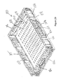
- a collapsible crate 210 according to a third embodiment of the present invention is shown in Figures 42-52 .
- the crate 210 includes a base 212, with side walls 214 and end walls 216 hingeably connected thereto.
- Each of the side walls 214 includes a first portion 218 (or door 218) and a second portion 220 selectively connected together.
- Latches 222 mounted on the first portion 218 selectively connect the first portion 218 to the second portion 220 and to the end wall 216.
- Each end wall 216 may include a handle opening 224 formed therein.
- Each end wall 216 is hingeably connected to an upstanding end portion 226, which may be integrally molded with the base 212.
- the first portion 218 and second portion 220 may each be approximately half the length of the side wall 214, or as shown in Figure 43 , the first portion 218 may be slightly shorter.
- the first portion 218 and the second portion 220 may each include a locating tab 230 projecting upwardly therefrom for interlocking with the base 212 of an identical crate 210 stacked thereon.
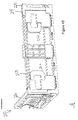
- Figure 44 is an interior perspective view of one of the corners of the crate 210.
- the first portion 218 is pivotably connected to the base 212 via hinge connectors 228.
- Each hinge connector 228 is pivotably connected at a lower end to the base 212 and pivotably and slidably connected at an upper end to the first portion 218.
- the latches 222 are shown connecting the first portion 218 to the second portion 220.
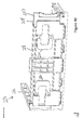
- Figure 45 is an exterior view of the corner of Figure 44 with the latches 222 in the latched position. Large, simple, sliding latches 222 that each connect at two vertically spaced points are shown, but other types of latches could also be used.
- Figure 46 shows the corner of Figure 44 with the latches moved to the unlatched position.
- the bottom of the first portion 218 can be pivoted out from the base 212 without significantly moving the upper edge of the first portion 218 upward.
- the bottom of the first portion 218 can be pivoted outward even when there is an identical crate stacked on the crate 210 to release the tab 230 from below the base 212 of the crate 210 stacked thereon.
- the hinge connectors 228 pivot and slide relative to the lower end of the first portion 218 and simply pivot relative to the base 212.
- Figure 48 the upper end of the first portion 218 of the side wall 214 can be directly moved outward (if no other crate is stacked on the crate 210).
- Figure 49 is an interior view of the first portion 218 being opened.
- the first portion 218 of the side wall 214 can also be pivoted outward to where it is flat on the floor.
- the hinge connectors 228 also make it possible for the side walls 214 to fold inward flat onto the base 212.
Landscapes
- Engineering & Computer Science (AREA)
- Mechanical Engineering (AREA)
- Rigid Containers With Two Or More Constituent Elements (AREA)
Applications Claiming Priority (3)
| Application Number | Priority Date | Filing Date | Title |
|---|---|---|---|
| US201261591842P | 2012-01-27 | 2012-01-27 | |
| US201261649214P | 2012-05-18 | 2012-05-18 | |
| US201261732907P | 2012-12-03 | 2012-12-03 |
Publications (1)
| Publication Number | Publication Date |
|---|---|
| EP2620380A1 true EP2620380A1 (fr) | 2013-07-31 |
Family
ID=47747358
Family Applications (1)
| Application Number | Title | Priority Date | Filing Date |
|---|---|---|---|
| EP13152902.6A Withdrawn EP2620380A1 (fr) | 2012-01-27 | 2013-01-28 | Récipient repliable avec une porte |
Country Status (4)
| Country | Link |
|---|---|
| US (2) | US10370145B2 (fr) |
| EP (1) | EP2620380A1 (fr) |
| CA (1) | CA2803726A1 (fr) |
| MX (1) | MX2013001129A (fr) |
Cited By (1)
| Publication number | Priority date | Publication date | Assignee | Title |
|---|---|---|---|---|
| CN109835570A (zh) * | 2019-02-27 | 2019-06-04 | 上海鸿研物流技术有限公司 | 可折叠容器 |
Families Citing this family (13)
| Publication number | Priority date | Publication date | Assignee | Title |
|---|---|---|---|---|
| JP6468870B2 (ja) * | 2015-02-02 | 2019-02-13 | 三甲株式会社 | 容器 |
| US9687852B2 (en) | 2015-04-14 | 2017-06-27 | Pall Corporation | Support for biocontainer bag |
| WO2017112840A1 (fr) | 2015-12-23 | 2017-06-29 | Arena Packaging, Llc | Contenant d'expédition de fruits et légumes |
| CA2960500A1 (fr) | 2016-03-11 | 2017-09-11 | Rehrig Pacific Company | Caisse ecrasable a apparence de bois |
| US10118727B2 (en) | 2016-09-15 | 2018-11-06 | Arena Packaging, Llc | Container having an access door latching system |
| US10065763B2 (en) | 2016-09-15 | 2018-09-04 | Arena Packaging, Llc | Wall latching system |
| US12448172B2 (en) | 2018-03-05 | 2025-10-21 | Rehrig Pacific Company | Collapsible container |
| US11597557B2 (en) | 2018-10-04 | 2023-03-07 | Rehrig Pacific Company | Reconfigurable beverage crate |
| US12330840B2 (en) * | 2019-02-04 | 2025-06-17 | Rehrig Pacific Company | Collapsible crate with retractable wall |
| WO2022170444A1 (fr) * | 2021-02-15 | 2022-08-18 | Wenco S.A. | Conteneur pour le transport de caisses et palette comprenant lesdits conteneurs |
| CA3172382A1 (fr) | 2021-09-16 | 2023-03-16 | Rehrig Pacific Company | Caisse escamotable hybride |
| JP2024101903A (ja) * | 2023-01-18 | 2024-07-30 | 河淳株式会社 | 陳列ケース |
| JP2024101902A (ja) * | 2023-01-18 | 2024-07-30 | 河淳株式会社 | 折り畳み陳列ケース |
Citations (4)
| Publication number | Priority date | Publication date | Assignee | Title |
|---|---|---|---|---|
| US6601724B1 (en) * | 1999-11-20 | 2003-08-05 | Rehrig Pacific Company | Collapsible merchandizing container |
| GB2449502A (en) * | 2007-05-25 | 2008-11-26 | Linpac Materials Handling Ltd | Collapsible container |
| EP2030903A1 (fr) * | 2007-08-28 | 2009-03-04 | Rehrig Pacific Company | Caisse avec mur démontable |
| DE102008024171A1 (de) * | 2008-05-19 | 2009-12-03 | Georg Utz Holding Ag | Transport- und Lagerbehälter |
Family Cites Families (10)
| Publication number | Priority date | Publication date | Assignee | Title |
|---|---|---|---|---|
| US705045A (en) * | 1901-11-25 | 1902-07-22 | George M Davidson | Hamper. |
| US1779159A (en) * | 1928-04-03 | 1930-10-21 | John E Coe | Tool box |
| GB2340485B (en) * | 1996-03-22 | 2000-08-23 | Mckechnie Uk Ltd | Containers |
| US5785328A (en) * | 1996-05-03 | 1998-07-28 | Star Metal Products, Inc. | Stackable cart assembly |
| US6702135B2 (en) * | 1999-10-27 | 2004-03-09 | Nathan L. Pickler | Universal dumpster |
| US6170689B1 (en) * | 1999-12-16 | 2001-01-09 | Apogee Designs, Ltd. | Collapsible container |
| US6227398B1 (en) * | 2000-01-14 | 2001-05-08 | Seville Classics | Collapsible hamper |
| US6318579B1 (en) * | 2000-07-25 | 2001-11-20 | Lynelle S. Leess | Roll-top trash can |
| WO2009091887A1 (fr) * | 2008-01-15 | 2009-07-23 | Defenshield, Inc. | Orifice d'accès à un panneau défensif |
| US8863971B2 (en) * | 2011-06-29 | 2014-10-21 | Rehrig Pacific Company | Crate with retractable wall |
-
2013
- 2013-01-28 EP EP13152902.6A patent/EP2620380A1/fr not_active Withdrawn
- 2013-01-28 US US13/752,142 patent/US10370145B2/en active Active
- 2013-01-28 MX MX2013001129A patent/MX2013001129A/es unknown
- 2013-01-28 CA CA2803726A patent/CA2803726A1/fr not_active Abandoned
-
2019
- 2019-05-09 US US16/407,864 patent/US12234057B2/en active Active
Patent Citations (4)
| Publication number | Priority date | Publication date | Assignee | Title |
|---|---|---|---|---|
| US6601724B1 (en) * | 1999-11-20 | 2003-08-05 | Rehrig Pacific Company | Collapsible merchandizing container |
| GB2449502A (en) * | 2007-05-25 | 2008-11-26 | Linpac Materials Handling Ltd | Collapsible container |
| EP2030903A1 (fr) * | 2007-08-28 | 2009-03-04 | Rehrig Pacific Company | Caisse avec mur démontable |
| DE102008024171A1 (de) * | 2008-05-19 | 2009-12-03 | Georg Utz Holding Ag | Transport- und Lagerbehälter |
Cited By (4)
| Publication number | Priority date | Publication date | Assignee | Title |
|---|---|---|---|---|
| CN109835570A (zh) * | 2019-02-27 | 2019-06-04 | 上海鸿研物流技术有限公司 | 可折叠容器 |
| EP3932821A4 (fr) * | 2019-02-27 | 2022-12-14 | Shanghai Hongyan Returnable Transit Packagings Co., Ltd. | Contenant pliable |
| US11820549B2 (en) | 2019-02-27 | 2023-11-21 | Horen Cortp Co., Ltd. | Foldable container |
| CN109835570B (zh) * | 2019-02-27 | 2024-02-27 | 上海鸿研物流技术有限公司 | 可折叠容器 |
Also Published As
| Publication number | Publication date |
|---|---|
| US10370145B2 (en) | 2019-08-06 |
| MX2013001129A (es) | 2013-07-26 |
| US20130193153A1 (en) | 2013-08-01 |
| US12234057B2 (en) | 2025-02-25 |
| US20190263561A1 (en) | 2019-08-29 |
| CA2803726A1 (fr) | 2013-07-27 |
Similar Documents
| Publication | Publication Date | Title |
|---|---|---|
| US12234057B2 (en) | Collapsible container with door | |
| US6234385B1 (en) | Side loading storage box | |
| US4192430A (en) | Laterally openable storage and transport box | |
| US4470518A (en) | Security box having a sliding lid | |
| EP2030903B1 (fr) | Caisse avec paroi escamotable | |
| US20100108556A1 (en) | Storage container | |
| US20110042259A1 (en) | Storage container | |
| MX2014011321A (es) | Contenedor con paredes inclinadas, lengüetas de apilamiento y esquinas reforzadas. | |
| US20090314827A1 (en) | Stackable corrugated box | |
| US20240043171A1 (en) | Containers for oil bottles or the like | |
| EP2289811B1 (fr) | Caisse pliable | |
| US20110215105A1 (en) | Transport and storage container | |
| CA2136554C (fr) | Conteneur demontable | |
| US20230257160A1 (en) | Collapsible box and methods of using same | |
| CA2985972A1 (fr) | Contenant ecrasable | |
| EP3994073B1 (fr) | Boîte pour stocker des articles et transporter des articles à la main | |
| US12234083B2 (en) | Collapsible container with slidable retractable wall | |
| JP5820282B2 (ja) | 蓋付き容器 | |
| KR102523660B1 (ko) | 박스용 테두리 부재보강부재와 에셈블리컨테이너 원터치크립이 포함된 박스 | |
| CN101304924A (zh) | 便携式可叠起堆放的塑料多功能容器 | |
| US20040173629A1 (en) | Reusable hinged-lid shipping/storage box | |
| KR200444006Y1 (ko) | 접이식 컨테이너 팔레트 시스템 | |
| EP0701520A1 (fr) | Conteneur a porte dote d'une partie montee sur charnieres et d'un volet coulissant | |
| JP2008239188A (ja) | 折り畳み容器 | |
| JP4575090B2 (ja) | 折り畳み容器 |
Legal Events
| Date | Code | Title | Description |
|---|---|---|---|
| PUAI | Public reference made under article 153(3) epc to a published international application that has entered the european phase |
Free format text: ORIGINAL CODE: 0009012 |
|
| AK | Designated contracting states |
Kind code of ref document: A1 Designated state(s): AL AT BE BG CH CY CZ DE DK EE ES FI FR GB GR HR HU IE IS IT LI LT LU LV MC MK MT NL NO PL PT RO RS SE SI SK SM TR |
|
| AX | Request for extension of the european patent |
Extension state: BA ME |
|
| 17P | Request for examination filed |
Effective date: 20140130 |
|
| RBV | Designated contracting states (corrected) |
Designated state(s): AL AT BE BG CH CY CZ DE DK EE ES FI FR GB GR HR HU IE IS IT LI LT LU LV MC MK MT NL NO PL PT RO RS SE SI SK SM TR |
|
| 17Q | First examination report despatched |
Effective date: 20150629 |
|
| STAA | Information on the status of an ep patent application or granted ep patent |
Free format text: STATUS: THE APPLICATION IS DEEMED TO BE WITHDRAWN |
|
| 18D | Application deemed to be withdrawn |
Effective date: 20170119 |