EP2620548B1 - Engin avec structure de cabine à oscillations découplées et dispositif d'attelage - Google Patents
Engin avec structure de cabine à oscillations découplées et dispositif d'attelage Download PDFInfo
- Publication number
- EP2620548B1 EP2620548B1 EP13000148.0A EP13000148A EP2620548B1 EP 2620548 B1 EP2620548 B1 EP 2620548B1 EP 13000148 A EP13000148 A EP 13000148A EP 2620548 B1 EP2620548 B1 EP 2620548B1
- Authority
- EP
- European Patent Office
- Prior art keywords
- construction machine
- stop
- machine frame
- lifting
- machine
- Prior art date
- Legal status (The legal status is an assumption and is not a legal conclusion. Google has not performed a legal analysis and makes no representation as to the accuracy of the status listed.)
- Active
Links
Images


Classifications
-
- B—PERFORMING OPERATIONS; TRANSPORTING
- B62—LAND VEHICLES FOR TRAVELLING OTHERWISE THAN ON RAILS
- B62D—MOTOR VEHICLES; TRAILERS
- B62D33/00—Superstructures for load-carrying vehicles
- B62D33/06—Drivers' cabs
- B62D33/0604—Cabs insulated against vibrations or noise, e.g. with elastic suspension
-
- B—PERFORMING OPERATIONS; TRANSPORTING
- B62—LAND VEHICLES FOR TRAVELLING OTHERWISE THAN ON RAILS
- B62D—MOTOR VEHICLES; TRAILERS
- B62D33/00—Superstructures for load-carrying vehicles
- B62D33/06—Drivers' cabs
- B62D33/0617—Drivers' cabs for tractors or off-the-road vehicles
- B62D33/0625—Drivers' cabs for tractors or off-the-road vehicles open
-
- E—FIXED CONSTRUCTIONS
- E01—CONSTRUCTION OF ROADS, RAILWAYS, OR BRIDGES
- E01C—CONSTRUCTION OF, OR SURFACES FOR, ROADS, SPORTS GROUNDS, OR THE LIKE; MACHINES OR AUXILIARY TOOLS FOR CONSTRUCTION OR REPAIR
- E01C19/00—Machines, tools or auxiliary devices for preparing or distributing paving materials, for working the placed materials, or for forming, consolidating, or finishing the paving
- E01C19/22—Machines, tools or auxiliary devices for preparing or distributing paving materials, for working the placed materials, or for forming, consolidating, or finishing the paving for consolidating or finishing laid-down unset materials
- E01C19/23—Rollers therefor; Such rollers usable also for compacting soil
-
- E—FIXED CONSTRUCTIONS
- E01—CONSTRUCTION OF ROADS, RAILWAYS, OR BRIDGES
- E01C—CONSTRUCTION OF, OR SURFACES FOR, ROADS, SPORTS GROUNDS, OR THE LIKE; MACHINES OR AUXILIARY TOOLS FOR CONSTRUCTION OR REPAIR
- E01C19/00—Machines, tools or auxiliary devices for preparing or distributing paving materials, for working the placed materials, or for forming, consolidating, or finishing the paving
- E01C19/22—Machines, tools or auxiliary devices for preparing or distributing paving materials, for working the placed materials, or for forming, consolidating, or finishing the paving for consolidating or finishing laid-down unset materials
- E01C19/23—Rollers therefor; Such rollers usable also for compacting soil
- E01C19/28—Vibrated rollers or rollers subjected to impacts, e.g. hammering blows
-
- E—FIXED CONSTRUCTIONS
- E02—HYDRAULIC ENGINEERING; FOUNDATIONS; SOIL SHIFTING
- E02F—DREDGING; SOIL-SHIFTING
- E02F9/00—Component parts of dredgers or soil-shifting machines, not restricted to one of the kinds covered by groups E02F3/00 - E02F7/00
- E02F9/16—Cabins, platforms, or the like, for drivers
- E02F9/166—Cabins, platforms, or the like, for drivers movable, tiltable or pivoting, e.g. movable seats, dampening arrangements of cabins
-
- E—FIXED CONSTRUCTIONS
- E01—CONSTRUCTION OF ROADS, RAILWAYS, OR BRIDGES
- E01C—CONSTRUCTION OF, OR SURFACES FOR, ROADS, SPORTS GROUNDS, OR THE LIKE; MACHINES OR AUXILIARY TOOLS FOR CONSTRUCTION OR REPAIR
- E01C2301/00—Machine characteristics, parts or accessories not otherwise provided for
- E01C2301/30—Cabin details
Definitions
- the invention relates to a construction machine according to the preamble of patent claim 1.
- helm structure comprising, for example, a driver's seat, a steering wheel and other controls for controlling the construction machine
- the control station structure as a whole is mounted on at least one damping element, for example a rubber bearing, on the machine frame.
- a known construction principle provides a control base plate connected to the machine frame via a plurality of damping elements, which carries the other components of the control station structure. The base plate is particularly often stored on a total of four damping elements on the machine frame.
- a vibration damping of the helm structure is particularly relevant in particular in such construction machines, in which at least one vibrating or vibrating working device is present, as is the case for example in tandem rollers with mounted in at least one bandage exciter.
- the vibration decoupling or vibration damping is accordingly designed in such a way that it dampens at least the transmission of the vibrations introduced by the exciter device into the machine for mounting the control station.
- Such vibration damping is disclosed, for example, in the American Patent Application Publication US 2009/0085377 A1 described in more detail.
- Ideal for attaching the hitch is especially the area of the helm structure. This is easily accessible from the outside and is often above or very close to the center of gravity of the construction machine, so that lifting by means of a one-point suspension is possible. A direct lifting of the construction machine on the disconnected control station itself, however, was not possible. A lifting of the construction machine on the control station structure always led to the control station structure pulled up the machine frame via the at least one damping element, so that significant tensile loads of at least one damping element occurred. This ultimately led to an overload up to the destruction of the at least one damping element. Accordingly, for example, the conveyor belt was carried out by the helm structure upwards.
- the articulation of the conveyor belt on the construction machine was carried out directly on the frame of the construction machine and not on the mounted on the machine frame helm structure.
- Especially ideal for attaching the suspension of the steering column of the construction machine is suitable because it is very accessible and also stored at the center of gravity of the construction machine, that it is suitable for a single-point suspension.
- the steering column is also vibration-decoupled in terms of ease of use attached to the control station structure, it was also not possible for the reasons mentioned above, to realize the suspension on the steering column support.
- the invention has for its object to provide a construction machine of the type mentioned, which does not involve the disadvantages associated with the prior art, or at least only in reduced extent.
- an easily accessible and low-wear possibility should be specified to couple a lifting device to a construction machine for lifting and moving the construction machine.
- the essential aspect of the invention is that a possibility is given to raise a generic construction machine via a directly on the control station arranged hitch, without causing the at least one damping element is overloaded.
- the invention is based on the finding that, on the one hand, a certain mobility of the control station structure relative to the frame during operation must be possible in order to achieve effective vibration decoupling. That is, the helm structure must be relatively movable with respect to the frame in working mode in a certain range. On the other hand, this area is generally much smaller than the deflection range of the helm structure relative to the frame (at least in lifting direction of the construction machine), from which irreversible damage to the at least one damping element occurs.
- the invention proposes for this purpose now that a Wegbegrenzungs Surprise is present, which limits the adjustment of the control station relative to the machine frame, and is designed in such a way that it limits the lifting of the construction machine, the load of at least one damping element on the hitch and a direct power flow between the helm structure and the machine frame allows.
- the limiting device is designed such that, at least during a lifting movement of the construction machine, it limits the relative mobility of the overhead structure relative to the machine frame in the lifting direction. As a result, an excessive tensile load of the damping element when lifting the construction machine is prevented.
- the inventive (path) limiting device thus combines several properties. On the one hand, it allows in a limited area a relative movement between the helm structure and the machine frame. In this limited area, the at least one damping element can thus dampen the vibration transmission from the machine frame to the control station structure. In this case, a bearing force transmission from the machine frame to the control gear assembly thus takes place via the at least one damping element.
- the limiting device prevents an excessive tensile load of the damping element in such a way that that now takes place a direct power flow between the machine frame and the helm structure, in particular over parts of the limiting device itself, and thereby overloading of the at least one damping element is prevented.
- the limiting device is designed in such a way that, starting from the stationary position of the construction machine, it permits a relative movement between the control station structure and the machine frame for damping purposes during operation in a certain area and if this area is exceeded, at least in the lifting direction, in particular due to tensile stress the helm structure when lifting the construction machine, which at least bypasses a damping element for transmitting power from the machine frame to the helm structure at least substantially and produces a direct power flow between the machine frame and the helm structure.
- the limiting device thus provides a means for limiting the travel distance between the control station structure and the machine frame at least in lifting direction of the construction machine, wherein the travel limit is formed in such a way that the possible adjustment is smaller than the at least one damping element beyond the usual wear out damaging adjustment due to excessive tensile load.
- the invention allows attachment of the suspension of a construction machine directly on the control station structure, or even directly to the steering column support, which is particularly well suited for lifting the construction machine due to their storage in the center of gravity, although the helm structure and the steering column are arranged vibration-decoupled on the machine frame.
- the limiting device is arranged, for example, at least partially between the machine frame and the control station structure. This positioning of the limiting device is advantageous insofar as it is particularly effective to realize a movement limitation between the machine frame and the control station structure.
- the specific configuration of the restricting device can be varied in a wide range as long as the above-mentioned effects of the restricting device are still obtained.
- the limiting device preferably works purely mechanically, and in principle also non-mechanical steps and / or means are possible, which are also included in the invention.
- the limiting device may include, for example, a, in particular between machine frame and the vibration-decoupled control stand effective effective, form-fitting coupling, the direct power flow between the helm structure and the machine frame over the form-locking coupling and bypassing a when lifting the construction machine on the hitch by inducing a positive connection allows further loading of the damping element.
- a form-locking coupling according to the invention is generally characterized by the fact that it comprises two elements which are releasably engageable in positive engagement, wherein in the form-closed state a direct power transmission from the machine frame to the helm structure (via the form-locking coupling, if this is not itself part of the machine frame and the helm structure ), at least in lifting direction of the construction machine, takes place.
- a lifting force applied to a hitch for example designed as a transport lug, which is attached to the operator's platform can be introduced directly into the machine frame, bypassing the damping elements.
- the form-locking coupling In the normal operating state of the construction machine, the form-locking coupling is not engaged, whereby the control station structure is elastically decoupled from the machine frame in a known manner and occurring vibrations in the machine frame relative to the control station structure are damped by the at least one damping element.
- the central component of the form-locking coupling are thus at least two elements designed for positive locking.
- the positive connection can take place via an intervention of the one element in the other element, as is the case, for example, with appropriately trained claws.
- particularly reliable in terms of function and easy to produce are positive locking elements which are obtained by a suitable stop, against which the other element abuts, at least in one direction of movement, and is thereby prevented from continuing the adjusting movement.
- the form-locking coupling of the construction machine according to the invention thus at least a first stop and at least a second stop or a stop element formed on each other in such a way that the second stop abuts the first stop when lifting the construction machine and a further relative movement of the helm structure to the machine frame prevented in lift direction.
- This type of positive coupling thus acts essentially by a Verstellwegbegrenzung of a stop against the other stop in lifting direction of the construction machine.
- the lifting direction of the construction machine is for the individual elements of the construction machine, in particular the machine frame and the control station structure, that direction in which the respective elements move when lifting the machine, in particular also to one another.
- One stop may be, for example, a passage opening and the other stop may be a stop pin guided through the passage opening.
- the terms stop and stop element are presently essentially functional to understand and designate a total of two when lifting the construction machine abutting each a stop comprehensive elements.
- the form-locking coupling comprises a stop on the control station structure and a stop or counter-stop on the machine frame and strike directly against each other.
- both the control station structure and the machine frame each have a stop which can be functionally coupled to each other via an intermediate element.
- the form-locking coupling further comprises at least the intermediate element, which is designed to abut against both stops when lifting the construction machine and thereby strictly speaking a double positive engagement (stop machine frame to intermediate element and intermediate element to abutment helm structure) allows and in the abutting state, a further relative movement of the helm structure to the machine frame locks.
- the positive locking elements which are arranged on the machine frame and the control station structure, not directly abut each other, but in each case on the intermediate element, which acts as a bridge element between the interlocking elements of the machine frame and the Fahrstand essentials.
- the power flow between the machine frame and the helm structure when lifting the construction machine is carried out when produced positive fit thus on the intermediate element.
- At least one stop of the machine frame and / or the helm structure is integrated into a holding leg projecting from the respective carrying part (the part which carries the holding leg).
- the holding leg connected fixedly to the machine frame or the control station structure is therefore essentially characterized by the fact that it protrudes spatially from the control station frame or from the machine frame and, on the other hand, fulfills a holding function for limitation of the relative movement between the machine frame and the control station structure as part of the form-locking coupling.
- a bolt passage opening is preferably integrated into the holding leg, through which a stop pin is feasible.
- each with a bolt passage opening is arranged both at the control station structure and the machine frame, wherein both bolt through openings are arranged overlapping each other at least in a partial area.
- the latter makes it possible to guide a linearly extended intermediate element, in particular a stop pin, through both bolt through openings.
- a linearly extended intermediate element in particular a stop pin
- the stop pin is further preferably arranged in such a way that its pin axis is perpendicular to the direction of the force of the lifting force, so that in the form-closed state, essentially shear forces are applied to the stop pin.
- the bolt axis is correspondingly preferably in a horizontal plane.
- the diameter of at least one bolt passage opening is preferably larger than the diameter of the stop bolt guided through the bolt passage opening, so that the bolt is mounted in this bolt passage opening limitedly movable (at least in the plane of the bolt passage opening) and only when lifting the construction machine to the edge of the bolt passage opening strikes. By this striking the positive locking is obtained and prevented a further adjustment of the helm structure relative to the machine frame when lifting the construction machine.
- the diameter of the respective bolt passage opening is particularly preferably formed circumferentially larger than the diameter of the stop pin. In this way, a relative movement between the machine frame and the control station structure in particularly many spatial directions and at least from the central position in all directions in the plane of the bolt passage opening is possible, which allows effective vibration damping by the at least one damping element.
- the gap width between the stopper bolt and the inner wall of the bolt passage opening is the decisive factor for determining how far the control gear assembly is movable relative to the machine frame.
- the gap width should in principle be dimensioned so that on the one hand the damping process for vibration isolation is not hindered by the form-fitting coupling and on the other hand the positive engagement occurs in good time before overloading the at least one damping element when lifting the construction machine.
- the gap width is often a few millimeters in practical use and is for example for a tandem roller in the range of 1 to 10 mm ..
- the specific design of the bolt passage opening can be varied in a variety of ways. Ideal, for example, a circular or disc-like design. Often, however, it may be desirable that various relative positions between the machine frame and the operator's cab structure or at least elements of them are possible.
- the use of one or more bolt through holes has proven that have a keyhole-shaped or a dumbbell-shaped contour.
- two RundlochausEnglish are thus connected to each other via a longitudinal slot. In both positions, in which the stop pin is guided through one of the two, ideally the same size, bolt through holes, thus resulting in the same adjustment, within which there is still a damping and no positive engagement.
- a stop pin in the form-locking coupling of Wegbegrenzungs is not mandatory.
- it comprises at least one first stop on the machine frame and at least one second stop on the control station structure, which are formed in the lift direction at least partially overlapping each other.
- at least two superimposed stops are present on the operator's station structure and on the machine frame in such a way that they come into contact with one another when lifting the construction machine, with the stop or the stop element of the machine frame then resting on the abutment of the chassis assembly.
- the form-locking coupling can be further simplified and formed more resilient, moreover, since an intermediate element, such as a stop pin, can be dispensed with here.
- the Wegbegrenzungs adopted and in particular the form-locking coupling has a stop in the form of a through hole, in particular in the machine frame, and a stop element in the form of a stop lug, in particular on the control station structure, wherein the stop lug in the stop opening at least partially substantially transversely to Lifting the construction machine protrudes.
- the stop lug and the passage opening are further preferably formed integrally with the control station structure and the machine frame, whereby on the one hand reduces the number of required components and usually the load capacity of Wegbegrenzungs adopted can be increased.
- the existing stop elements are preferably formed at least in pairs, so that takes place when lifting the construction machine Wegbegrenzungs Rhein and in particular the form-locking coupling the Hebekraftübertragung simultaneously at several points of the form-locking coupling.
- the path limiting device and in particular the form-locking coupling is preferably formed in such a way that when lifting the construction machine, the positive connection automatically or automatically, where it is in principle also possible that the positive coupling is actively actuated by the operator of the construction machine.
- the former has the advantage that the relief effect of the at least one damping element achieved by the form-locking coupling according to the invention is independent of human intervention and thus particularly reliable.
- the form-locking coupling is further preferably formed in such a way that they automatically reach when a fixed maximum adjustment of the helm structure relative to the machine frame engages at least in lifting direction of the construction machine. The maximum adjustment is usefully set in such a way that when it is reached no damage to the at least one damping element occurs.
- the limiting device according to the invention and in particular the form-locking coupling and the direct power flow between the control station frame and the machine frame or the power flow between the control station frame and the machine frame bypassing further loading of the at least one damping element allow the arrangement of at least one towing device, in particular transport lug, on the control station structure or at least in a fixed connection with the control station structure and thus at a connection point which is favorable in terms of accessibility, introduction of force (in particular with regard to the resulting tilting moments) and / or resulting force flow.
- Under a transport tab or the like is understood a machine element to which a tensile force or lifting force can be applied.
- the transport tab z. B.
- a preferred embodiment of the construction machine according to the invention provides that it has only a single transport tab, said single transport tab is arranged on the vibration-decoupled control station structure. Due to the resulting one-point suspension a very simple handling when lifting, loading or the like is possible.
- the towing device in particular the transport tab
- the towing device is arranged on a steering column which belongs to the control station structure.
- the steering column is in this case connected to the base plate of the chassis assembly part on which the steering wheel or other steering device is arranged on the construction machine.
- the steering column is often pillar-like in the vertical direction upwards from the base plate and has in its upper part a steering wheel and / or other control, such as a dashboard, on.
- the transport tab is thus arranged on an already present on the construction machine and exposed positioned component, so that no additional components to be provided on the construction machine according to the invention for attaching the transport tab.
- the towing device in particular the transport tab, can also be adjustably arranged, for example, pivotable and / or hinged, on the control station structure and in particular on the steering column. In this way, the hitch can be removed from the field of view of the operator of the construction machine in the working mode when it is not needed.
- the construction machine is a tandem roller, in particular with an operating weight of up to 6.0 t, preferably of up to 5.0 t.
- Fig. 1 shows a tandem roller 100 as an example of a self-propelled construction machine.
- the tandem roller 100 has a front bandage 101 and a rear bandage 102, which are mounted on a machine frame 103.
- the machine frame 103 comprises two via an articulation 104 with each other connected machine frame segments, wherein the one segment, the front bandage 101 and the other segment, the rear bandage 102 carries.
- the front forward a segment lying further comprises a hood, whereas on the rear segment of the machine frame 103, a driving position structure 106 is arranged.
- the driver's cab structure 106 further includes a towering in the vertical direction steering column 108, at the upper end of a steering wheel and a dashboard are arranged. Further details on the control station structure 106 result in particular Fig. 2 ,
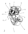
- Fig. 2 illustrates the basic structure of the Fahrstand inconveniences 106 and its storage on the machine frame 103 of the tandem roller 100.
- the supporting element of the Fahrstand incompletes 106 is a bottom or base plate 111, the present case a horizontal foot portion 112 (with a footboard), one vertically offset to the top horizontal seating area 113 and a connecting area 114 obtained in the form of a vertical wall and connecting the areas 112 and 113, wherein the parts 112, 113 and 114 are firmly connected, ideally in one piece, and form the base plate 111 in their entirety.
- On the bottom plate 111 further elements of the chassis assembly are arranged, for example, the not shown seat in the rear and the steering column support 108.
- the steering column support vertically upwards and protrudes in this direction over the foot portion 112.
- a transport tab 115 hitch is arranged on the steering column support 108.
- Fig. 2 shows the transport tab 115 in its downwardly pivoted position.
- the transport tab 115 can be pivoted up in the direction of arrow b.
- the transporting lug 115 has a transport lug 116, through which a corresponding hook, for example connected to a crane, or the like can be threaded.
- the steering column support 108 is fixedly connected to the bottom plate 111 of the helm structure 106.
- the transport lug 116 to form the steering column support 108 stationary.
- the control station superstructure 106 is mounted on the machine frame 103, wherein the bearing is vibration-damped or vibration-decoupled (ie the vibrations occurring on the machine frame 103 are not forwarded one to one but, if at all, damped to the control gear superstructure 106).
- the vibrations developed during operation on the excitation units of the two bandages 101 and 102 are thus, if at all, damped transferred to the base or bottom plate 111 and to the entire further control station structure 106.
- the base plate 111 is provided with a total of four damping elements 117 on the machine frame 103, which is also stepped in this area (in FIG Fig. 2 only the part of the machine frame 103 opposite the bottom plate 111 is shown).
- the damping elements 117 are suitable rubber elements, whose elastic deformability thus makes possible a relative movement of the chassis assembly 106 relative to the machine frame 103 for vibration damping.
- the damping elements 117 ensure during operation of the tandem roller 100 in a certain area an elastic decoupling of the chassis assembly 106 relative to the machine frame 103.
- the towering from the base plate 111 steering column support 108 is welded to the base plate 111.
- the center of gravity of the tandem roller 100 is in Fig. 1 roughly indicated by S and is located in the vertical direction substantially below the transport tab 115.
- the vertical force application line of the lifting force F (or its extension) runs essentially through the center of gravity S of the tandem roller 100, which is why the tandem roller 100 does not tilt during lifting.
- the transport tab 115 is attached to the already existing on the tandem roller 100 and with respect to the point of force of the lifting force F favorable steering column support 108, no additional components for attaching the transport tab 115 are required.
- FIGS. 2 to 7b The basic structure of Wegbegrenzungs leads results in particular further from the FIGS. 2 to 7b , where the FIGS. 2 to 4 and the FIGS. 5 to 7b merely by way of example relate to two different alternative embodiments.
- the form-locking coupling 1 ' is arranged between the control station structure 106 and the machine frame 103, wherein the essential elements of the form-locking coupling 1' in the present embodiment lie almost on a vertical with the center of gravity S and the transport flap 115.
- the form-locking coupling 1 ' is effective only when lifting the tandem roller 100, but then automatically and automatically, allowing a direct flow of force between the Fahrstand integral 106 and the machine frame 103, bypassing the damping elements 117. This ensures that the load on the damping elements 117 during lifting the construction machine is not above its maximum load.
- the intended maximum deflection of the chassis assembly 106 relative to the machine frame 103 is achieved, wherein the tensile load of the damping elements 117 prevailing at this point is maintained even when the form-locking coupling is activated.
- the maximum deflection is determined by the design of the form-locking coupling 1 '.
- this tensile load is much smaller than the lifting force required for lifting the construction machine and therefore negligible.
- the form-fitting coupling 1 'thus takes over the force transmission between the machine frame 103 and Fahrstand essential 106 while avoiding overloading of the damping elements 117.
- the form-fitting coupling 1' prevents corresponding damage to the damping elements 117, which are not designed by design for high tensile forces, and allows In addition, also a substantially deflection-free power flow between the control station structure 106 and the steering column support 108 and the machine frame 103rd
- the stop pin 6 projects beyond in the axial direction of the bolt 6 in the axial direction on both sides outer holding leg 2 on the machine frame 103 and is secured on both sides against displacement in the axial direction (concretely on suitable disc elements 10 and / or screw heads 8 and 9, whose diameter is larger is as the diameter of the bolt through holes 3 of the holding legs. 2
- the Figures 2 . 3 and 4 in each case show the form-fitting coupling 1 'in the uncoupled state, for example, when the tandem roller 100 rests on the ground.
- the stop pin 6 can move freely within the bolt through openings 5, in particular in the vertical direction (and in the present case also in the horizontal direction), and is ultimately secured only against an axial displacement.
- the bolt through hole 5 thus rotates the stopper pin 6 at a distance.
- the stop pin 6 is fixed in the vertical direction and mounted firmly in this guide.
- the position of the undercarriage structure 106 or the bottom plate 111 relative to the machine frame 103 is essentially ensured by the damping elements 117, which elastically hold the control station structure 106 on the machine frame 103 in position.
- the form-fitting coupling 1 ' is formed in such a way that the stop pin 6 extends in the idle state of the stationary construction machine 100 centrally through the bolt passage openings 5. In this way, it is ensured that an attenuation of the chassis assembly 106 relative to the machine frame 103 via the damping elements 117 in both the vertical direction and in and against the working direction is possible.
- the Fahrstand initial 106 is first, at least in the region of the form-locking coupling 1 ', raised in a limited adjustment relative to the machine frame 103. This relative movement takes place until the stop pin 6 abuts against the lower opening edges of the bolt passage openings 5, as indicated by the arrows d in the cross-sectional view Fig. 4 is indicated.
- the edge of the bolt passage opening 5 thus forms in the lifting direction c a first stop 20 with respect to the second or counter-stop 21 formed by the stop pin 6.
- the stop point is in Fig. 4 marked with I.
- the limits of this adjustment range are determined by the distance .DELTA.H of the stop pin 6 to the respective stops on the bolt passage openings 5 in the lifting direction c.
- the narrower ⁇ H the earlier the positive locking occurs and vice versa.
- the lifting force F applied to the transport flap 115 can then be introduced directly into the machine frame 103 via this form-fit, bypassing the damping elements 117.
- the form-fitting coupling 1 'in extreme conditions occurring during operation of the present case designed as a tandem roller 100 construction machine also serve as a tear-off for the helm structure 106. This can be a significant security issue.
- the form-fitting coupling 1 'can also serve as a mechanical stop element which, for example to protect the damping elements 117, limits the maximum travel of the control station structure 106 relative to the machine frame 103, wherein the stopper pin 6 both to the upper edges and to the lower edges of the Bolzen micsö Maschinenmaschine devisen 5 can strike.
- FIG. 4 is a sectional view along the section line AA Fig. 3
- Fig. 4 illustrates in particular the arrangement of the stop pin 6 and its relative position and mode of action as a stop element (second stop 21) to the arranged in the retaining legs 2 and 4 bolt through holes 3 and 5.
- the pin axis of the stop pin 6 extends in the horizontal plane and perpendicular to the lifting direction c.
- the stop pin 6 is passed through the two bolt through holes 3 of the fixedly connected to the machine frame 103 holding leg 2 and the bolt through holes 5 of the fixed to the bottom plate 111 of the chassis assembly 108 holding leg 4 and is on both sides in the axial direction in each case one of the outer sides of the holding leg 2 ago.
- the front side, a bolt head 8 and a screwed onto the stop pin 6 nut 9 is present, which rest against a respective locking washer 10.
- the stop pin 6 is correspondingly easy to disassemble in the form-locking coupling 1 'installed.
- the lock washers 10 are sized so that they are larger in diameter than the bolt through holes 3 and 5, whereby the stopper pin 6 is secured against total axial displacement.
- the bolt longitudinal axis 7 thus extends horizontally and perpendicular to the force application line of the lifting force in lifting direction c.
- Another essential feature of the form-locking coupling 1 ' is that the cylinder outer shell of the stop pin 6 at the in Fig. 4 shown operating position (ie, the tandem roller 100 is on the ground and can or is operated) with the distance .DELTA.H to the edge of the bolt through holes 5 in the radial direction to the pin axis 7 is spaced.
- the distance ⁇ H is obtained in that the diameter of the stop pin 6 is smaller by the amount 2 * ( ⁇ H) than the diameter of the bolt through holes 5, which in the present case have the same dimensions.
- the stopper bolt is in other words not at the bolt through hole 5, so that the control station structure 108 is movable relative to the machine frame 103.
- tandem roller 100 is raised in the lift direction c via the transport flap 115, a relative movement of the driver's station structure 108 relative to the machine frame 103 in the direction c takes place, with the stop pin 6 approaching the respective edge of the bolt passage opening 5 in the direction of arrow d.
- FIGS. 5 to 7b relate to an alternative embodiment of the form-locking coupling 1 ', wherein only the differences will be discussed below and otherwise with respect to the structure and operation of the form-locking coupling 1' and the other elements of the construction machine 100 reference is made to the above statements.
- FIGS. 5 to 7b show the FIGS. 5 to 7b only a part of the construction machine 100 Fig. 1 namely, the machine frame 103 (rear segment) and the control gear frame 106 mounted on the machine frame 103.
- Fig. 5 is a perspective oblique view
- Fig. 6a a sectional view through Fig. 5 along the cutting plane xx (sectional plane in the vertical direction and in the longitudinal direction or in the opposite direction a)
- Fig. 5 is a perspective oblique view
- Fig. 6a a sectional view through Fig. 5 along the cutting plane xx (sectional plane in the vertical direction and in the longitudinal direction or in the opposite direction a)
- FIGS. 6b and 7b are each detail enlargements of the dashed framed area of the FIGS. 6a and 7a , which illustrate in particular the structure and operation of the form-locking coupling 1 'between the control station structure 106 and the machine frame 103.
- the main difference in the structure of the positive coupling 1 ' is that in the FIGS. 5 to 7b embodiment shown does not have a separate stop pin, but alone integrally or integrally with the machine frame 103 and the Fahrstand inconvenience 106 formed elements includes, in particular, the first stop 20 and the second stop 21 of the form-locking coupling 1 'form.
- the machine frame 103 and the operator's station superstructure 106 are designed such that they form the interlocking coupling 1 'together in the mounted state and without additional elements.
- the required stops 20 and 21 of the form-locking coupling 1 ' are each formed integrally and integrally with the control station structure 106 or the machine frame 103.
- the form-fitting coupling 1 ' according to the embodiment in the Figures 5 . 6a . 6b . 7a and 7b comprises on the machine frame 103 two juxtaposed and projecting from the machine frame 103 in the region of the steering column 108 holding leg 2, which open with respect to their top in the forward direction a respectively in a through hole 50 in a front plate 51 of the machine frame 103.
- the retaining legs 2 thus extend in the forward direction a in the horizontal plane from a lying within the machine frame 103 area to the edge of the machine frame 103 and each open at its upper side in the passage opening 50.
- the top 52 of the retaining legs 2 is as supporting surface in more detail below formed manner described.
- Counter-element of the form-locking coupling 1 'on the control station structure 106 to the elements "holding leg 2" and "through hole 50" on the machine frame 103 are the two from the bottom of the Fahrstand essentials 106 downwardly projecting holding or support leg 4. These are each a holding leg 2 overlapping in the vertical direction arranged and have in addition to a contact surface 52 further comprises a stop or engagement nose 53, which is guided in the horizontal plane or substantially transversely to the lifting direction c through the passage opening 50 therethrough. Overall, the two stop lugs 53 thus extend in the manner of two prongs which project through the passage openings 50 in the front plate 51 of the machine frame 103 in the direction of travel a and terminate almost flush with the front plate 51. Fig.
- the through holes 50 are formed in terms of their width (horizontal transversely to the direction of travel a) and height (extension in the vertical direction) greater than the stop lugs 53, so that the stop lugs 53 are moved within a certain range without contact relative to the inner edge of the through holes 50 can. This is desirable, for example, in the working mode of the construction machine, if a vibration decoupling between the control station structure 106 and the machine frame 103 is to be achieved by the damping elements 117.
- the spacing is indicated by ⁇ H.
- FIGS. 6a, 6b . 7a and 7b The operation of this positive coupling 1 'is in a synopsis of FIGS. 6a, 6b . 7a and 7b further described.
- the Figures 6a and 6b correspond to the in Fig. 5 (and in Fig. 1 ) illustrated situation in which the construction machine 100 rests on the ground and can be used in the present case, for example, to compaction work.
- the FIGS. 7a and 7b on the other hand concern the transport situation in which the construction machine is attached via the transport tab 115 to a lifting device, for example to a crane, and thus does not stand up with their bandages on the ground. As already mentioned above, the lifting takes place solely via the transport tab 115 corresponding to a single-point suspension.
- the construction machine is ideally designed in such a way that the machine center of gravity S lies in the perpendicular in the horizontal plane or at least as close to the perpendicular to the transport lug 115 in order to allow the construction machine 100 to rise as easily as possible.
- the slightly inclined in the working position steering column 108 first by the angle ⁇ (in a vertical plane in the direction of a) to the rear or the helm structure including steering column 108 kinks at this angle relative to the machine frame 103 in its center.
- the course of the front of the steering column 108 is made Fig. 7a in Fig. 6a dotted indicated.
- FIGS. 6a / 6b A comparison of Figures 6a / 6b with the Figures 7a / 7b illustrates that the control station structure 106 relative to the machine frame 103 performs a Einknickterrorism in the direction of arrow d.
- the damping elements 117 the front in the direction of travel damping elements are not visible here but in their structure and their arrangement identical to the in Fig. 2 shown embodiment
- the machine frame 103 mounted control station structure 106 in the region of the form-locking coupling 1 'in stop position and is detected in a continuation of the lifting movement in the direction c relative to the machine frame 103.
- this is done to intervene the form-locking coupling 1 ', wherein the control station structure 106 abuts the machine frame 103 several times. This is illustrated in particular by the FIGS. 6b and 7b ,
- the holding leg 4 rotate together with their stop lugs 53 about a horizontal axis of rotation transverse to the direction of work a.
- the stop lug 53 with its upper side forming the stop 21, abuts the stop 20 formed by the underside of the passage opening 50 in the machine frame 103.
- the peculiarity of the present embodiment of the form-locking coupling 1 'lies in the fact that the control gear assembly 106 additionally with its retaining legs 4 to the retaining legs 2, concretely their top 52 abuts, and thus wedged the helm structure 106 relative to the machine frame 103.
- the retaining legs 2 on the machine frame and the retaining legs 4 on the control station structure are thus arranged in pairs in the vertical direction overlapping each other or superimposed, so that the holding leg 2 can be supported on the holding legs 4 when lifting the construction machine 100.
- a total of three stop locations per holding leg pair 2/4 between the control station superstructure 106 and the machine frame 103 are in Fig. 7b with I, II and III indicated.
- the Switzerlandkraftschreib Arthurhausentechnisch from Fahrstand essential 106 in the machine frame 103 is essentially at the stop I.
- At the stop I is the upper edge of the passage opening 50 (stop 20) on the top of the stop lug 53 (stop element 21).
- a holding leg 2 of the machine frame 103 presses with its top against the underside of each holding leg 4 of the helm structure, which is caused by the relative tilting movement of the helm structure 106 in this area relative to the machine frame 103.
- the form-locking coupling 1 automatically disengages.
- the support legs 2 and 4 are, however, spaced from each other by the distance .DELTA.H in the vertical direction, so that a vibration damping of the machine frame 103 is ensured to the Fahrstand essential 106 via the damping elements 117.
- the stop lugs are circumferentially spaced from the inner edge of the passage opening 50 and protrude without contact through the passage opening 50.
Landscapes
- Engineering & Computer Science (AREA)
- Structural Engineering (AREA)
- Civil Engineering (AREA)
- Transportation (AREA)
- Chemical & Material Sciences (AREA)
- Combustion & Propulsion (AREA)
- Mechanical Engineering (AREA)
- Architecture (AREA)
- Mining & Mineral Resources (AREA)
- General Engineering & Computer Science (AREA)
- Body Structure For Vehicles (AREA)
- Jib Cranes (AREA)
- Vibration Prevention Devices (AREA)
Claims (13)
- Engin de chantier (100), en particulier machine pour la construction de routes, comprenant un châssis de machine (103) et une structure (106) de plateforme pour un conducteur qui est à découplage vibratoire en relation avec le châssis (103) de machine grâce à au moins un élément amortisseur (117),
caractérisé en ce que
l'engin de chantier (100) comprend un dispositif d'attelage (115) pour soulever l'engin de chantier (100), le dispositif d'attelage (115) étant situé sur la structure (106) de plateforme pour le conducteur, et un dispositif limiteur de course (1) étant prévu, qui limite la course de déplacement de la plateforme pour le conducteur par rapport au châssis de la machine, et qui est mis en oeuvre de telle sorte que, lorsqu'on soulève l'engin de chantier (100) grâce au dispositif d'attelage (115), il limite la charge sur ledit au moins un élément amortisseur (117), empêche une charge de traction excessive sur ledit au moins un élément amortisseur (117) lorsqu'on soulève l'engin de chantier (100) et permet un flux de forces direct entre la structure (106) de plateforme pour le conducteur et le châssis (103) de machine. - Engin de chantier (100) selon la revendication 1,
caractérisé en ce que
le dispositif limiteur de course comprend une liaison (1') par accouplement de formes, qui est active en particulier entre la structure (106) de plateforme pour le conducteur à découplage vibratoire et le châssis (103) de machine, et qui permet le flux de forces direct entre la structure (106) de plateforme pour le conducteur et le châssis (103) de machine lorsqu'on soulève l'engin de chantier (100) via le dispositif d'attelage (115) par formation d'un accouplement de formes. - Engin de chantier (100) selon la revendication 2,
caractérisé en ce que
la liaison (1') par accouplement de formes comprend au moins une première butée (20) et au moins une deuxième butée (21), qui sont formées l'une par rapport à l'autre de telle sorte que ladite au moins une première butée (20) vient buter contre ladite au moins une deuxième butée (21) lorsqu'on soulève l'engin de chantier (100) et empêche un déplacement relatif de la structure (106) de plateforme pour le conducteur par rapport au châssis (103) de machine dans la direction (c) de levage. - Engin de chantier (100) selon l'une quelconque des revendications 2 ou 3,
caractérisé en ce que
la liaison (1') par accouplement de formes comprend au moins une butée (20) sur la structure (106) de plateforme pour le conducteur et au moins une butée (21) sur le châssis (103) de machine. - Engin de chantier (100) selon l'une quelconque des revendications 2 à 4,
caractérisé en ce que
ladite au moins une deuxième butée (21) est un boulon d'arrêt (6) qui vient en contact avec ladite au moins une première butée (3) lorsqu'on soulève l'engin de construction, avec en particulier un bras de retenue (4) présentant une ouverture (5) de passage pour un boulon et disposé sur la structure (106) de plateforme pour le conducteur, et un bras de retenue (2) présentant une ouverture (3) de passage pour un boulon et disposé recouvrant au moins partiellement le châssis (103) de machine, et en ce que le boulon d'arrêt (6) est guidé à travers les deux ouvertures (3, 5) de passage pour un boulon d'une manière telle qu'il s'appuie contre le bord des deux ouvertures (3, 5) de passage pour un boulon lorsqu'on soulève l'engin de chantier (100). - Engin de chantier (100) selon la revendication 5,
caractérisé en ce que
l'axe (7) du boulon d'arrêt (6) s'étend perpendiculairement à la direction d'une force de levage (F). - Engin de chantier (100) selon l'une quelconque des revendications 1 à 4,
caractérisé en ce que
le dispositif limiteur de course (1), et en particulier la liaison (1') par accouplement de formes, comprend au moins une première butée (20) sur le châssis (103) de machine et au moins une deuxième butée (21) sur la structure (106) de plateforme pour le conducteur, qui sont mises en oeuvre comme se recouvrant au moins partiellement l'une par rapport à l'autre dans la direction de levage. - Engin de chantier (100) selon l'une quelconque des revendications 1 à 4 ou 7,
caractérisé en ce que
le dispositif limiteur de course (1), et en particulier la liaison (1') par accouplement de formes, comprend une première butée (20) prenant la forme d'une ouverture de passage (50), en particulier dans le châssis (103) de machine, et une deuxième butée (21) prenant la forme d'un talon d'arrêt (53), en particulier sur la structure (106) de plateforme pour le conducteur, le talon d'arrêt (53) faisant saillie au moins partiellement dans l'ouverture de passage (50) de manière essentiellement transversale à la direction de levage de l'engin de chantier. - Engin de chantier (100) selon l'une quelconque des revendications précédentes,
caractérisé en ce que
les éléments du dispositif limiteur de course (1), et en particulier de la liaison (1') par accouplement de formes, sont réalisés d'une seule pièce avec la structure (106) de plateforme pour un conducteur et le châssis (103) de machine. - Engin de chantier (100) selon l'une quelconque des revendications précédentes,
caractérisé en ce que
le dispositif limiteur de course (1) comprend au moins une limitation d'inclinaison, qui limite le mouvement d'inclinaison de la structure (106) de plateforme pour un conducteur par rapport au châssis (103) de machine. - Engin de chantier (100) selon l'une quelconque des revendications précédentes,
caractérisé en ce que
le dispositif d'attelage est une manille de transport (115) qui est fixée sur la structure (106) de plateforme pour un conducteur à découplage vibratoire. - Engin de chantier (100) selon l'une quelconque des revendications précédentes,
caractérisé en ce que
il possède au moins l'une des caractéristiques suivantes :(a) le dispositif d'attelage, et en particulier la manille de transport (115), est disposé sur une colonne de support de direction (108) réunie à la structure (106) de plateforme pour le conducteur;(b) la manille de transport (115) est agencée de manière à être pivotante et/ou repliable sur la structure (106) de plateforme pour le conducteur, et en particulier sur la colonne de support de direction (108). - Engin de chantier (100) selon l'une quelconque des revendications précédentes,
caractérisé en ce que
il s'agit d'un rouleau tandem ayant une masse en exploitation allant jusqu'à 6,0 tonnes, et en particulier jusqu'à 5,0 tonnes.
Applications Claiming Priority (1)
| Application Number | Priority Date | Filing Date | Title |
|---|---|---|---|
| DE102012001348A DE102012001348A1 (de) | 2012-01-24 | 2012-01-24 | Baumaschine, insbesondere Straßenbaumaschine, beispielsweise Tandemwalze, mit schwingungsentkoppeltem Fahrstandaufbau und mit einer Anhängeeinrichtung |
Publications (3)
| Publication Number | Publication Date |
|---|---|
| EP2620548A2 EP2620548A2 (fr) | 2013-07-31 |
| EP2620548A3 EP2620548A3 (fr) | 2014-01-08 |
| EP2620548B1 true EP2620548B1 (fr) | 2015-11-04 |
Family
ID=47559271
Family Applications (1)
| Application Number | Title | Priority Date | Filing Date |
|---|---|---|---|
| EP13000148.0A Active EP2620548B1 (fr) | 2012-01-24 | 2013-01-11 | Engin avec structure de cabine à oscillations découplées et dispositif d'attelage |
Country Status (3)
| Country | Link |
|---|---|
| US (1) | US8602679B2 (fr) |
| EP (1) | EP2620548B1 (fr) |
| DE (1) | DE102012001348A1 (fr) |
Families Citing this family (7)
| Publication number | Priority date | Publication date | Assignee | Title |
|---|---|---|---|---|
| DE202012003217U1 (de) * | 2012-03-29 | 2013-07-01 | Joseph Vögele AG | Außensteuerstand für eine Baumaschine |
| CN103993539B (zh) * | 2014-05-26 | 2016-04-13 | 池州腾虎机械科技有限公司 | 压路机激振器间及其与同步同向驱动齿轮箱间的定位结构 |
| GB201601279D0 (en) * | 2016-01-25 | 2016-03-09 | Mccartney Toby | A method of producing a road making material and to a road made therefrom |
| DE102016007170A1 (de) * | 2016-06-13 | 2017-12-14 | Bomag Gmbh | Gummiradwalze |
| CN110593057B (zh) * | 2019-08-26 | 2021-10-01 | 广东博智林机器人有限公司 | 抹平机器人 |
| US11753794B2 (en) | 2020-02-03 | 2023-09-12 | Caterpillar Inc. | Single point lifting structure for a work machine |
| EP4378877A1 (fr) * | 2022-11-29 | 2024-06-05 | Volvo Construction Equipment AB | Ensemble support pour soulever une machine articulée |
Family Cites Families (10)
| Publication number | Priority date | Publication date | Assignee | Title |
|---|---|---|---|---|
| US3213769A (en) * | 1962-01-22 | 1965-10-26 | Smith John William | Machine for spreading and compacting surfacing material |
| US4496265A (en) * | 1983-01-28 | 1985-01-29 | Fragale Joseph V | Compact asphalt laying machine for sidewalks and the like |
| US4643611A (en) * | 1985-04-08 | 1987-02-17 | Wacker Corporation | Vibratory compactor having improved cast base |
| US4964753A (en) * | 1988-06-17 | 1990-10-23 | Stone Construction Equipment, Inc. | Three roll compactor |
| DE9206391U1 (de) * | 1992-05-12 | 1992-08-27 | Karl Schaeff GmbH & Co, Maschinenfabrik, 7183 Langenburg | Arbeitsgerät zum Abbruch oder Aufbau von Mauern |
| US5522670A (en) * | 1995-03-15 | 1996-06-04 | Granite Rock Company | Hitching mechanism |
| JP2002266311A (ja) * | 2001-03-09 | 2002-09-18 | Sakai Heavy Ind Ltd | 転圧機械 |
| US8182024B2 (en) * | 2006-05-31 | 2012-05-22 | Caterpillar Inc. | Structure and a system for connecting a machine cab to a supporting frame |
| JP4996742B2 (ja) * | 2008-04-25 | 2012-08-08 | 株式会社小松製作所 | 作業機械のキャブストッパ装置及びその組付け方法、並びに作業機械のキャブ |
| JP5291596B2 (ja) * | 2009-11-02 | 2013-09-18 | 酒井重工業株式会社 | 締固め機械におけるフードの開閉構造 |
-
2012
- 2012-01-24 DE DE102012001348A patent/DE102012001348A1/de not_active Withdrawn
-
2013
- 2013-01-11 EP EP13000148.0A patent/EP2620548B1/fr active Active
- 2013-01-23 US US13/747,923 patent/US8602679B2/en not_active Expired - Fee Related
Also Published As
| Publication number | Publication date |
|---|---|
| EP2620548A3 (fr) | 2014-01-08 |
| EP2620548A2 (fr) | 2013-07-31 |
| DE102012001348A1 (de) | 2013-07-25 |
| US8602679B2 (en) | 2013-12-10 |
| US20130189033A1 (en) | 2013-07-25 |
Similar Documents
| Publication | Publication Date | Title |
|---|---|---|
| EP2620548B1 (fr) | Engin avec structure de cabine à oscillations découplées et dispositif d'attelage | |
| EP2134600B1 (fr) | Agencement de filet pour une soute, de preference dans un avion | |
| EP2177670B1 (fr) | Châssis porteur pour un appareil de travail mobile | |
| DE102005034463B3 (de) | Lastkraftwagen mit Seilzugkippvorrichtung für das Fahrerhaus | |
| EP1520939A2 (fr) | Chargeur | |
| EP2864548B2 (fr) | Dispositif pour compaction d'un sol | |
| EP2617622A1 (fr) | Dispositif de soutien vertical d'une barre d'attelage | |
| EP0710620B1 (fr) | Tablier de support pour pont élévateur avec plaque support | |
| DE2944289A1 (de) | Hebefahrzeug | |
| EP4039633B1 (fr) | Châssis de véhicule à grue mobile pourvu de pièces amovibles de châssis | |
| DE102005034465B4 (de) | Lastkraftwagen mit Kollisionsrückhaltesystem für das Fahrerhaus | |
| EP2457752B1 (fr) | Dispositif d'embrayage et dispositif d'attelage pour véhicules tracteurs | |
| DE10143716A1 (de) | Mobiles Arbeitsgerät mit Stützträgern und Verfahren zum Betrieb dieses Arbeitsgeräts | |
| WO2019115003A1 (fr) | Machine automotrice de fraisage de sol | |
| EP3995436A1 (fr) | Grue mobile pourvue de ballast de tourelle réglable en hauteur | |
| DE1003604B (de) | Anbauvorrichtung fuer endlose Gleisketten an Ackerschleppern u. dgl. | |
| EP1120376B1 (fr) | Machine de pose de conduites | |
| DE9408196U1 (de) | Schnellwechselvorrichtung | |
| DE1781069A1 (de) | Hubstaplermast mit Fuehrungsrollen und Verfahren zu deren Einbau und Wartung | |
| EP1640309B1 (fr) | Dispositif de levage et arrangement de câble | |
| EP3611083B1 (fr) | Plaque d'accouplement pour une sellette d attelage | |
| DE102022105934B4 (de) | Mobilkran mit einer Gegengewichtsvorrichtung | |
| EP0903076B1 (fr) | Protecteur de collision pour appareil de travail agricole tracté | |
| DE102009013262A1 (de) | Scharniereinrichtung für eine Frontklappe eines Kraftfahrzeugs | |
| AT400946B (de) | Chassis für raupenfahrwerke |
Legal Events
| Date | Code | Title | Description |
|---|---|---|---|
| PUAI | Public reference made under article 153(3) epc to a published international application that has entered the european phase |
Free format text: ORIGINAL CODE: 0009012 |
|
| AK | Designated contracting states |
Kind code of ref document: A2 Designated state(s): AL AT BE BG CH CY CZ DE DK EE ES FI FR GB GR HR HU IE IS IT LI LT LU LV MC MK MT NL NO PL PT RO RS SE SI SK SM TR |
|
| AX | Request for extension of the european patent |
Extension state: BA ME |
|
| RIN1 | Information on inventor provided before grant (corrected) |
Inventor name: ROETSCH, HELMUT Inventor name: HAMMEN, BJOERN Inventor name: BENDER, MATTHIAS |
|
| PUAL | Search report despatched |
Free format text: ORIGINAL CODE: 0009013 |
|
| AK | Designated contracting states |
Kind code of ref document: A3 Designated state(s): AL AT BE BG CH CY CZ DE DK EE ES FI FR GB GR HR HU IE IS IT LI LT LU LV MC MK MT NL NO PL PT RO RS SE SI SK SM TR |
|
| AX | Request for extension of the european patent |
Extension state: BA ME |
|
| RIC1 | Information provided on ipc code assigned before grant |
Ipc: E01C 19/28 20060101AFI20131204BHEP Ipc: B62D 33/06 20060101ALI20131204BHEP Ipc: E02F 9/16 20060101ALI20131204BHEP Ipc: E01C 19/23 20060101ALI20131204BHEP |
|
| 17P | Request for examination filed |
Effective date: 20140702 |
|
| RBV | Designated contracting states (corrected) |
Designated state(s): AL AT BE BG CH CY CZ DE DK EE ES FI FR GB GR HR HU IE IS IT LI LT LU LV MC MK MT NL NO PL PT RO RS SE SI SK SM TR |
|
| GRAP | Despatch of communication of intention to grant a patent |
Free format text: ORIGINAL CODE: EPIDOSNIGR1 |
|
| INTG | Intention to grant announced |
Effective date: 20150623 |
|
| GRAS | Grant fee paid |
Free format text: ORIGINAL CODE: EPIDOSNIGR3 |
|
| GRAA | (expected) grant |
Free format text: ORIGINAL CODE: 0009210 |
|
| AK | Designated contracting states |
Kind code of ref document: B1 Designated state(s): AL AT BE BG CH CY CZ DE DK EE ES FI FR GB GR HR HU IE IS IT LI LT LU LV MC MK MT NL NO PL PT RO RS SE SI SK SM TR |
|
| REG | Reference to a national code |
Ref country code: GB Ref legal event code: FG4D Free format text: NOT ENGLISH |
|
| REG | Reference to a national code |
Ref country code: CH Ref legal event code: EP |
|
| REG | Reference to a national code |
Ref country code: AT Ref legal event code: REF Ref document number: 759279 Country of ref document: AT Kind code of ref document: T Effective date: 20151115 |
|
| REG | Reference to a national code |
Ref country code: IE Ref legal event code: FG4D Free format text: LANGUAGE OF EP DOCUMENT: GERMAN |
|
| REG | Reference to a national code |
Ref country code: DE Ref legal event code: R096 Ref document number: 502013001426 Country of ref document: DE |
|
| REG | Reference to a national code |
Ref country code: NL Ref legal event code: MP Effective date: 20151104 |
|
| REG | Reference to a national code |
Ref country code: LT Ref legal event code: MG4D |
|
| REG | Reference to a national code |
Ref country code: CH Ref legal event code: NV Representative=s name: HEPP WENGER RYFFEL AG, CH |
|
| PG25 | Lapsed in a contracting state [announced via postgrant information from national office to epo] |
Ref country code: LT Free format text: LAPSE BECAUSE OF FAILURE TO SUBMIT A TRANSLATION OF THE DESCRIPTION OR TO PAY THE FEE WITHIN THE PRESCRIBED TIME-LIMIT Effective date: 20151104 Ref country code: NO Free format text: LAPSE BECAUSE OF FAILURE TO SUBMIT A TRANSLATION OF THE DESCRIPTION OR TO PAY THE FEE WITHIN THE PRESCRIBED TIME-LIMIT Effective date: 20160204 Ref country code: IS Free format text: LAPSE BECAUSE OF FAILURE TO SUBMIT A TRANSLATION OF THE DESCRIPTION OR TO PAY THE FEE WITHIN THE PRESCRIBED TIME-LIMIT Effective date: 20160304 Ref country code: IT Free format text: LAPSE BECAUSE OF FAILURE TO SUBMIT A TRANSLATION OF THE DESCRIPTION OR TO PAY THE FEE WITHIN THE PRESCRIBED TIME-LIMIT Effective date: 20151104 Ref country code: ES Free format text: LAPSE BECAUSE OF FAILURE TO SUBMIT A TRANSLATION OF THE DESCRIPTION OR TO PAY THE FEE WITHIN THE PRESCRIBED TIME-LIMIT Effective date: 20151104 Ref country code: NL Free format text: LAPSE BECAUSE OF FAILURE TO SUBMIT A TRANSLATION OF THE DESCRIPTION OR TO PAY THE FEE WITHIN THE PRESCRIBED TIME-LIMIT Effective date: 20151104 Ref country code: HR Free format text: LAPSE BECAUSE OF FAILURE TO SUBMIT A TRANSLATION OF THE DESCRIPTION OR TO PAY THE FEE WITHIN THE PRESCRIBED TIME-LIMIT Effective date: 20151104 |
|
| PG25 | Lapsed in a contracting state [announced via postgrant information from national office to epo] |
Ref country code: PT Free format text: LAPSE BECAUSE OF FAILURE TO SUBMIT A TRANSLATION OF THE DESCRIPTION OR TO PAY THE FEE WITHIN THE PRESCRIBED TIME-LIMIT Effective date: 20160304 Ref country code: SE Free format text: LAPSE BECAUSE OF FAILURE TO SUBMIT A TRANSLATION OF THE DESCRIPTION OR TO PAY THE FEE WITHIN THE PRESCRIBED TIME-LIMIT Effective date: 20151104 Ref country code: RS Free format text: LAPSE BECAUSE OF FAILURE TO SUBMIT A TRANSLATION OF THE DESCRIPTION OR TO PAY THE FEE WITHIN THE PRESCRIBED TIME-LIMIT Effective date: 20151104 Ref country code: PL Free format text: LAPSE BECAUSE OF FAILURE TO SUBMIT A TRANSLATION OF THE DESCRIPTION OR TO PAY THE FEE WITHIN THE PRESCRIBED TIME-LIMIT Effective date: 20151104 Ref country code: BE Free format text: LAPSE BECAUSE OF NON-PAYMENT OF DUE FEES Effective date: 20160131 Ref country code: LV Free format text: LAPSE BECAUSE OF FAILURE TO SUBMIT A TRANSLATION OF THE DESCRIPTION OR TO PAY THE FEE WITHIN THE PRESCRIBED TIME-LIMIT Effective date: 20151104 Ref country code: FI Free format text: LAPSE BECAUSE OF FAILURE TO SUBMIT A TRANSLATION OF THE DESCRIPTION OR TO PAY THE FEE WITHIN THE PRESCRIBED TIME-LIMIT Effective date: 20151104 Ref country code: GR Free format text: LAPSE BECAUSE OF FAILURE TO SUBMIT A TRANSLATION OF THE DESCRIPTION OR TO PAY THE FEE WITHIN THE PRESCRIBED TIME-LIMIT Effective date: 20160205 |
|
| REG | Reference to a national code |
Ref country code: DE Ref legal event code: R097 Ref document number: 502013001426 Country of ref document: DE |
|
| PG25 | Lapsed in a contracting state [announced via postgrant information from national office to epo] |
Ref country code: EE Free format text: LAPSE BECAUSE OF FAILURE TO SUBMIT A TRANSLATION OF THE DESCRIPTION OR TO PAY THE FEE WITHIN THE PRESCRIBED TIME-LIMIT Effective date: 20151104 Ref country code: DK Free format text: LAPSE BECAUSE OF FAILURE TO SUBMIT A TRANSLATION OF THE DESCRIPTION OR TO PAY THE FEE WITHIN THE PRESCRIBED TIME-LIMIT Effective date: 20151104 Ref country code: SK Free format text: LAPSE BECAUSE OF FAILURE TO SUBMIT A TRANSLATION OF THE DESCRIPTION OR TO PAY THE FEE WITHIN THE PRESCRIBED TIME-LIMIT Effective date: 20151104 Ref country code: LU Free format text: LAPSE BECAUSE OF FAILURE TO SUBMIT A TRANSLATION OF THE DESCRIPTION OR TO PAY THE FEE WITHIN THE PRESCRIBED TIME-LIMIT Effective date: 20160111 Ref country code: SM Free format text: LAPSE BECAUSE OF FAILURE TO SUBMIT A TRANSLATION OF THE DESCRIPTION OR TO PAY THE FEE WITHIN THE PRESCRIBED TIME-LIMIT Effective date: 20151104 Ref country code: RO Free format text: LAPSE BECAUSE OF FAILURE TO SUBMIT A TRANSLATION OF THE DESCRIPTION OR TO PAY THE FEE WITHIN THE PRESCRIBED TIME-LIMIT Effective date: 20151104 |
|
| PLBE | No opposition filed within time limit |
Free format text: ORIGINAL CODE: 0009261 |
|
| STAA | Information on the status of an ep patent application or granted ep patent |
Free format text: STATUS: NO OPPOSITION FILED WITHIN TIME LIMIT |
|
| PG25 | Lapsed in a contracting state [announced via postgrant information from national office to epo] |
Ref country code: MC Free format text: LAPSE BECAUSE OF FAILURE TO SUBMIT A TRANSLATION OF THE DESCRIPTION OR TO PAY THE FEE WITHIN THE PRESCRIBED TIME-LIMIT Effective date: 20151104 |
|
| 26N | No opposition filed |
Effective date: 20160805 |
|
| REG | Reference to a national code |
Ref country code: FR Ref legal event code: ST Effective date: 20160930 |
|
| REG | Reference to a national code |
Ref country code: IE Ref legal event code: MM4A |
|
| PG25 | Lapsed in a contracting state [announced via postgrant information from national office to epo] |
Ref country code: SI Free format text: LAPSE BECAUSE OF FAILURE TO SUBMIT A TRANSLATION OF THE DESCRIPTION OR TO PAY THE FEE WITHIN THE PRESCRIBED TIME-LIMIT Effective date: 20151104 Ref country code: FR Free format text: LAPSE BECAUSE OF NON-PAYMENT OF DUE FEES Effective date: 20160201 |
|
| PG25 | Lapsed in a contracting state [announced via postgrant information from national office to epo] |
Ref country code: IE Free format text: LAPSE BECAUSE OF NON-PAYMENT OF DUE FEES Effective date: 20160111 |
|
| PGFP | Annual fee paid to national office [announced via postgrant information from national office to epo] |
Ref country code: CH Payment date: 20170103 Year of fee payment: 5 |
|
| PG25 | Lapsed in a contracting state [announced via postgrant information from national office to epo] |
Ref country code: MT Free format text: LAPSE BECAUSE OF FAILURE TO SUBMIT A TRANSLATION OF THE DESCRIPTION OR TO PAY THE FEE WITHIN THE PRESCRIBED TIME-LIMIT Effective date: 20151104 |
|
| GBPC | Gb: european patent ceased through non-payment of renewal fee |
Effective date: 20170111 |
|
| PG25 | Lapsed in a contracting state [announced via postgrant information from national office to epo] |
Ref country code: GB Free format text: LAPSE BECAUSE OF NON-PAYMENT OF DUE FEES Effective date: 20170111 |
|
| PG25 | Lapsed in a contracting state [announced via postgrant information from national office to epo] |
Ref country code: CY Free format text: LAPSE BECAUSE OF FAILURE TO SUBMIT A TRANSLATION OF THE DESCRIPTION OR TO PAY THE FEE WITHIN THE PRESCRIBED TIME-LIMIT Effective date: 20151104 Ref country code: HU Free format text: LAPSE BECAUSE OF FAILURE TO SUBMIT A TRANSLATION OF THE DESCRIPTION OR TO PAY THE FEE WITHIN THE PRESCRIBED TIME-LIMIT; INVALID AB INITIO Effective date: 20130111 |
|
| PG25 | Lapsed in a contracting state [announced via postgrant information from national office to epo] |
Ref country code: TR Free format text: LAPSE BECAUSE OF FAILURE TO SUBMIT A TRANSLATION OF THE DESCRIPTION OR TO PAY THE FEE WITHIN THE PRESCRIBED TIME-LIMIT Effective date: 20151104 Ref country code: MK Free format text: LAPSE BECAUSE OF FAILURE TO SUBMIT A TRANSLATION OF THE DESCRIPTION OR TO PAY THE FEE WITHIN THE PRESCRIBED TIME-LIMIT Effective date: 20151104 |
|
| PG25 | Lapsed in a contracting state [announced via postgrant information from national office to epo] |
Ref country code: BG Free format text: LAPSE BECAUSE OF FAILURE TO SUBMIT A TRANSLATION OF THE DESCRIPTION OR TO PAY THE FEE WITHIN THE PRESCRIBED TIME-LIMIT Effective date: 20151104 |
|
| REG | Reference to a national code |
Ref country code: CH Ref legal event code: PL |
|
| PG25 | Lapsed in a contracting state [announced via postgrant information from national office to epo] |
Ref country code: AL Free format text: LAPSE BECAUSE OF FAILURE TO SUBMIT A TRANSLATION OF THE DESCRIPTION OR TO PAY THE FEE WITHIN THE PRESCRIBED TIME-LIMIT Effective date: 20151104 |
|
| PG25 | Lapsed in a contracting state [announced via postgrant information from national office to epo] |
Ref country code: CH Free format text: LAPSE BECAUSE OF NON-PAYMENT OF DUE FEES Effective date: 20180131 Ref country code: LI Free format text: LAPSE BECAUSE OF NON-PAYMENT OF DUE FEES Effective date: 20180131 |
|
| REG | Reference to a national code |
Ref country code: AT Ref legal event code: MM01 Ref document number: 759279 Country of ref document: AT Kind code of ref document: T Effective date: 20180111 |
|
| PG25 | Lapsed in a contracting state [announced via postgrant information from national office to epo] |
Ref country code: AT Free format text: LAPSE BECAUSE OF NON-PAYMENT OF DUE FEES Effective date: 20180111 |
|
| P01 | Opt-out of the competence of the unified patent court (upc) registered |
Effective date: 20230527 |
|
| REG | Reference to a national code |
Ref country code: DE Ref legal event code: R082 Ref document number: 502013001426 Country of ref document: DE Representative=s name: ZIMMERMANN & PARTNER PATENTANWAELTE MBB, DE |
|
| PGFP | Annual fee paid to national office [announced via postgrant information from national office to epo] |
Ref country code: CZ Payment date: 20251230 Year of fee payment: 14 |
|
| PGFP | Annual fee paid to national office [announced via postgrant information from national office to epo] |
Ref country code: DE Payment date: 20260120 Year of fee payment: 14 |