EP2620594B1 - Méthode de fabrication de composant de turbine à matériaux multiples - Google Patents
Méthode de fabrication de composant de turbine à matériaux multiples Download PDFInfo
- Publication number
- EP2620594B1 EP2620594B1 EP13151337.6A EP13151337A EP2620594B1 EP 2620594 B1 EP2620594 B1 EP 2620594B1 EP 13151337 A EP13151337 A EP 13151337A EP 2620594 B1 EP2620594 B1 EP 2620594B1
- Authority
- EP
- European Patent Office
- Prior art keywords
- turbine
- article
- forming
- intermediate component
- component
- Prior art date
- Legal status (The legal status is an assumption and is not a legal conclusion. Google has not performed a legal analysis and makes no representation as to the accuracy of the status listed.)
- Not-in-force
Links
Images

Classifications
-
- B—PERFORMING OPERATIONS; TRANSPORTING
- B22—CASTING; POWDER METALLURGY
- B22F—WORKING METALLIC POWDER; MANUFACTURE OF ARTICLES FROM METALLIC POWDER; MAKING METALLIC POWDER; APPARATUS OR DEVICES SPECIALLY ADAPTED FOR METALLIC POWDER
- B22F5/00—Manufacture of workpieces or articles from metallic powder characterised by the special shape of the product
- B22F5/009—Manufacture of workpieces or articles from metallic powder characterised by the special shape of the product of turbine components other than turbine blades
-
- B—PERFORMING OPERATIONS; TRANSPORTING
- B22—CASTING; POWDER METALLURGY
- B22F—WORKING METALLIC POWDER; MANUFACTURE OF ARTICLES FROM METALLIC POWDER; MAKING METALLIC POWDER; APPARATUS OR DEVICES SPECIALLY ADAPTED FOR METALLIC POWDER
- B22F10/00—Additive manufacturing of workpieces or articles from metallic powder
- B22F10/20—Direct sintering or melting
- B22F10/28—Powder bed fusion, e.g. selective laser melting [SLM] or electron beam melting [EBM]
-
- B—PERFORMING OPERATIONS; TRANSPORTING
- B22—CASTING; POWDER METALLURGY
- B22F—WORKING METALLIC POWDER; MANUFACTURE OF ARTICLES FROM METALLIC POWDER; MAKING METALLIC POWDER; APPARATUS OR DEVICES SPECIALLY ADAPTED FOR METALLIC POWDER
- B22F10/00—Additive manufacturing of workpieces or articles from metallic powder
- B22F10/60—Treatment of workpieces or articles after build-up
- B22F10/64—Treatment of workpieces or articles after build-up by thermal means
-
- B—PERFORMING OPERATIONS; TRANSPORTING
- B22—CASTING; POWDER METALLURGY
- B22F—WORKING METALLIC POWDER; MANUFACTURE OF ARTICLES FROM METALLIC POWDER; MAKING METALLIC POWDER; APPARATUS OR DEVICES SPECIALLY ADAPTED FOR METALLIC POWDER
- B22F5/00—Manufacture of workpieces or articles from metallic powder characterised by the special shape of the product
- B22F5/04—Manufacture of workpieces or articles from metallic powder characterised by the special shape of the product of turbine blades
-
- B—PERFORMING OPERATIONS; TRANSPORTING
- B22—CASTING; POWDER METALLURGY
- B22F—WORKING METALLIC POWDER; MANUFACTURE OF ARTICLES FROM METALLIC POWDER; MAKING METALLIC POWDER; APPARATUS OR DEVICES SPECIALLY ADAPTED FOR METALLIC POWDER
- B22F7/00—Manufacture of composite layers, workpieces, or articles, comprising metallic powder, by sintering the powder, with or without compacting wherein at least one part is obtained by sintering or compression
- B22F7/06—Manufacture of composite layers, workpieces, or articles, comprising metallic powder, by sintering the powder, with or without compacting wherein at least one part is obtained by sintering or compression of composite workpieces or articles from parts, e.g. to form tipped tools
-
- B—PERFORMING OPERATIONS; TRANSPORTING
- B23—MACHINE TOOLS; METAL-WORKING NOT OTHERWISE PROVIDED FOR
- B23P—METAL-WORKING NOT OTHERWISE PROVIDED FOR; COMBINED OPERATIONS; UNIVERSAL MACHINE TOOLS
- B23P15/00—Making specific metal objects by operations not covered by a single other subclass or a group in this subclass
- B23P15/04—Making specific metal objects by operations not covered by a single other subclass or a group in this subclass turbine or like blades from several pieces
-
- C—CHEMISTRY; METALLURGY
- C30—CRYSTAL GROWTH
- C30B—SINGLE-CRYSTAL GROWTH; UNIDIRECTIONAL SOLIDIFICATION OF EUTECTIC MATERIAL OR UNIDIRECTIONAL DEMIXING OF EUTECTOID MATERIAL; REFINING BY ZONE-MELTING OF MATERIAL; PRODUCTION OF A HOMOGENEOUS POLYCRYSTALLINE MATERIAL WITH DEFINED STRUCTURE; SINGLE CRYSTALS OR HOMOGENEOUS POLYCRYSTALLINE MATERIAL WITH DEFINED STRUCTURE; AFTER-TREATMENT OF SINGLE CRYSTALS OR A HOMOGENEOUS POLYCRYSTALLINE MATERIAL WITH DEFINED STRUCTURE; APPARATUS THEREFOR
- C30B11/00—Single-crystal growth by normal freezing or freezing under temperature gradient, e.g. Bridgman-Stockbarger method
-
- B—PERFORMING OPERATIONS; TRANSPORTING
- B22—CASTING; POWDER METALLURGY
- B22F—WORKING METALLIC POWDER; MANUFACTURE OF ARTICLES FROM METALLIC POWDER; MAKING METALLIC POWDER; APPARATUS OR DEVICES SPECIALLY ADAPTED FOR METALLIC POWDER
- B22F10/00—Additive manufacturing of workpieces or articles from metallic powder
- B22F10/30—Process control
- B22F10/36—Process control of energy beam parameters
-
- B—PERFORMING OPERATIONS; TRANSPORTING
- B22—CASTING; POWDER METALLURGY
- B22F—WORKING METALLIC POWDER; MANUFACTURE OF ARTICLES FROM METALLIC POWDER; MAKING METALLIC POWDER; APPARATUS OR DEVICES SPECIALLY ADAPTED FOR METALLIC POWDER
- B22F12/00—Apparatus or devices specially adapted for additive manufacturing; Auxiliary means for additive manufacturing; Combinations of additive manufacturing apparatus or devices with other processing apparatus or devices
- B22F12/30—Platforms or substrates
-
- B—PERFORMING OPERATIONS; TRANSPORTING
- B33—ADDITIVE MANUFACTURING TECHNOLOGY
- B33Y—ADDITIVE MANUFACTURING, i.e. MANUFACTURING OF THREE-DIMENSIONAL [3D] OBJECTS BY ADDITIVE DEPOSITION, ADDITIVE AGGLOMERATION OR ADDITIVE LAYERING, e.g. BY 3D PRINTING, STEREOLITHOGRAPHY OR SELECTIVE LASER SINTERING
- B33Y10/00—Processes of additive manufacturing
-
- B—PERFORMING OPERATIONS; TRANSPORTING
- B33—ADDITIVE MANUFACTURING TECHNOLOGY
- B33Y—ADDITIVE MANUFACTURING, i.e. MANUFACTURING OF THREE-DIMENSIONAL [3D] OBJECTS BY ADDITIVE DEPOSITION, ADDITIVE AGGLOMERATION OR ADDITIVE LAYERING, e.g. BY 3D PRINTING, STEREOLITHOGRAPHY OR SELECTIVE LASER SINTERING
- B33Y30/00—Apparatus for additive manufacturing; Details thereof or accessories therefor
-
- B—PERFORMING OPERATIONS; TRANSPORTING
- B33—ADDITIVE MANUFACTURING TECHNOLOGY
- B33Y—ADDITIVE MANUFACTURING, i.e. MANUFACTURING OF THREE-DIMENSIONAL [3D] OBJECTS BY ADDITIVE DEPOSITION, ADDITIVE AGGLOMERATION OR ADDITIVE LAYERING, e.g. BY 3D PRINTING, STEREOLITHOGRAPHY OR SELECTIVE LASER SINTERING
- B33Y80/00—Products made by additive manufacturing
-
- C—CHEMISTRY; METALLURGY
- C30—CRYSTAL GROWTH
- C30B—SINGLE-CRYSTAL GROWTH; UNIDIRECTIONAL SOLIDIFICATION OF EUTECTIC MATERIAL OR UNIDIRECTIONAL DEMIXING OF EUTECTOID MATERIAL; REFINING BY ZONE-MELTING OF MATERIAL; PRODUCTION OF A HOMOGENEOUS POLYCRYSTALLINE MATERIAL WITH DEFINED STRUCTURE; SINGLE CRYSTALS OR HOMOGENEOUS POLYCRYSTALLINE MATERIAL WITH DEFINED STRUCTURE; AFTER-TREATMENT OF SINGLE CRYSTALS OR A HOMOGENEOUS POLYCRYSTALLINE MATERIAL WITH DEFINED STRUCTURE; APPARATUS THEREFOR
- C30B29/00—Single crystals or homogeneous polycrystalline material with defined structure characterised by the material or by their shape
- C30B29/10—Inorganic compounds or compositions
- C30B29/52—Alloys
-
- Y—GENERAL TAGGING OF NEW TECHNOLOGICAL DEVELOPMENTS; GENERAL TAGGING OF CROSS-SECTIONAL TECHNOLOGIES SPANNING OVER SEVERAL SECTIONS OF THE IPC; TECHNICAL SUBJECTS COVERED BY FORMER USPC CROSS-REFERENCE ART COLLECTIONS [XRACs] AND DIGESTS
- Y02—TECHNOLOGIES OR APPLICATIONS FOR MITIGATION OR ADAPTATION AGAINST CLIMATE CHANGE
- Y02P—CLIMATE CHANGE MITIGATION TECHNOLOGIES IN THE PRODUCTION OR PROCESSING OF GOODS
- Y02P10/00—Technologies related to metal processing
- Y02P10/25—Process efficiency
-
- Y—GENERAL TAGGING OF NEW TECHNOLOGICAL DEVELOPMENTS; GENERAL TAGGING OF CROSS-SECTIONAL TECHNOLOGIES SPANNING OVER SEVERAL SECTIONS OF THE IPC; TECHNICAL SUBJECTS COVERED BY FORMER USPC CROSS-REFERENCE ART COLLECTIONS [XRACs] AND DIGESTS
- Y10—TECHNICAL SUBJECTS COVERED BY FORMER USPC
- Y10T—TECHNICAL SUBJECTS COVERED BY FORMER US CLASSIFICATION
- Y10T29/00—Metal working
- Y10T29/49—Method of mechanical manufacture
- Y10T29/49316—Impeller making
- Y10T29/49336—Blade making
Definitions
- the present invention generally relates to turbine engines, and more particularly relates to turbine components and methods for manufacturing turbine components or other components for engines.
- Gas turbine engines are generally known in the art and used in a wide range of applications, such as propulsion engines and auxiliary power unit engines for aircraft.
- a turbine section of the engine includes turbine components such as rows of stator vanes and rotor blades disposed in an alternating sequence along the axial length of a generally annular hot gas flow path.
- the rotor blades are mounted on the periphery of rotor disks coupled to a main engine shaft.
- the stator vanes are coupled to inner and outer endwalls and optimally direct hot combustion gases to the rotor blades, thus resulting in rotary driving of the rotor disks to provide an engine output.
- stator vanes and rotor blades typically have arcuate shapes with generally concave pressure sides and generally convex suction sides extending axially in chords between opposite leading and trailing edges.
- aerodynamic contours of the stator vanes and rotor blades, and corresponding flow passages between are configured in an attempt to maximize energy extraction from the combustion gases. Since higher engine efficiencies may occur at higher temperatures, some turbine components may additionally include internal cooling passages to enable such high temperature operation.
- turbine components may have relatively complex three-dimensional (3D) geometries that may raise difficult fabrication issues.
- Conventional fabrication techniques include forging, casting, and/or machining.
- a ceramic core is assembled into a wax tool that will provide the external shape of the component, the core is encased in wax, a ceramic shell is formed around the wax pattern, and the wax is removed to form a ceramic mold.
- Molten metal is then poured into the mold, cooled and solidified, and then the external shell and internal core are suitably removed to result in the desired turbine component.
- the cast turbine component may then undergo subsequent manufacturing processes such as machining, electrical discharge machining (EDM) or laser drilling.
- EDM electrical discharge machining
- EP 2319641 discloses a method to apply multiple materials with selective laser melting on a three-dimensional article, such as using a metal powder.
- US 2005/0268998 discloses a method for producing a three-dimensional moulded body, layer by layer, using a laser and a metal powder.
- US5554837 discloses a process and apparatus for laser welding a nickel and/or cobalt based superalloy article comprising: preheating the entire weld area and adjacent region to a ductile temperature with an induction heat coil and maintaining such temperature during welding and solidification of the weld; and welding the preheated article utilizing a laser with a powder alloy feed with a control means controlling the laser, power feed and motion system on which the article is fixtured, wherein the control means includes a vision system which digitizes the weld area providing a path for the laser welding to follow.
- a turbine component for a turbine of an engine includes a blade portion of a first material; and an attachment portion coupled to the blade portion, the attachment portion being a second material.
- a method for manufacturing an engine component includes providing a first portion of an intermediate component article, the first portion comprising a first material; forming a second portion of the intermediate component article on the first portion of the intermediate component article with an additive manufacturing technique, the second portion comprising a second material; and finishing the intermediate component article to form the engine component
- exemplary embodiments discussed herein include turbine components or other components of gas turbine engines and methods for manufacturing such components.
- the components may be manufactured in sections or portions with materials selected for each portion that optimize the resulting properties.
- a turbine component may be manufactured with a blade portion of a first material, a tip portion with a second material, and an attachment portion of a third material, with each material being selected based on the individual function of the respective portion.
- one or more of the portions are formed with additive manufacturing techniques such as direct metal laser fusion.
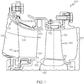
- FIG. 1 is a partial cross-sectional view of a turbine section 100 of a gas turbine engine assembly in accordance with an exemplary embodiment.
- the turbine section 100 and gas turbine engine assembly have an overall construction and operation that are generally understood by persons skilled in the art.
- the turbine section 100 has a housing 102 with an annular duct wall 104 that defines a mainstream hot gas flow path 106 for receiving a flow of mainstream combustion gases 108 from an engine combustor (not shown).
- the housing 102 additionally houses at least one stator assembly 110 with stator vanes 120 and at least one turbine rotor assembly 130 with turbine rotor blades (or airfoils) 132.
- the rotor blades 132 of the turbine rotor assembly 130 project radially outward toward a shroud flange 122 from a turbine rotor platform 134 that is coupled to a turbine disk 136, which in turn circumscribes a shaft (not shown).
- the rotor platform 134 may include one or more flow discouragers 138 that assist in maintaining efficient air flow along the mainstream hot gas flow path 106.
- combustion gases 108 flow past axially spaced circumferential rows of stator vanes 120 and rotor blades 132 to drive the rotor blades 132 and the associated turbine rotor assembly 130 for power extraction.
- Other embodiments may have different configurations.
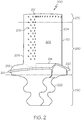
- FIG. 2 is an isometric view of a turbine component 200 in accordance with an exemplary embodiment and generally illustrates the relatively complex 3D geometric configuration typical of a turbine component, for example, that may be incorporated into the turbine section 100 of FIG. 1 .
- the turbine component 200 in FIG. 2 is depicted as a rotor blade, such as rotor blade 132 ( FIG. 1 )
- the exemplary embodiments discussed herein are applicable to any type of turbine component, including stator vanes, such as stator vanes 120 ( FIG. 1 ), turbine shrouds, such as shroud flanges 122 ( FIG. 1 ), and other types of engine components.
- the turbine component 200 is an airfoil 202 with a generally concave pressure side 204 and a generally convex suction side 206 opposed thereto and joined at a leading edge 208 and a trailing edge 210.
- the airfoil 202 extends from a tip 212 to a root 214, which is coupled to a platform 216 that defines an inner boundary for the hot combustion gases that pass over airfoil 202 during engine operation.
- the platform 216 may further include flow discouragers 218 and 220 that function to discourage hot gas ingestion into undesired areas.
- a mounting dovetail 222 may be integrally formed on the underside of the platform 216 for mounting the turbine component 200 within the turbine section 100 ( FIG. 1 ).
- the turbine component 200 may include internal passages or hollow areas to provide a cooling flow during engine operation, although in other embodiments, the turbine component 200 may be solid.
- the turbine component 200 may be considered with respect to one or more sections or portions 250, 270, and 290.
- the portions 250, 270, and 290 may include a blade portion 250, a tip portion 270, and a hub portion 290.
- These specific portions are merely exemplary and used in the examples discussed below, although in other embodiments, other portions may be considered.
- each portion 250, 270, and 290 may be optimized for a particular function.
- the geometry of each portion 250, 270, and 290 is designed to achieve a designated function.
- the material used to manufacture each portion 250, 270, and 290 may be selected to provide desired properties.
- the blade portion 250 of the turbine component 200 is typically subject to the highest temperatures, and as such, the material used to manufacture the blade portion 250 may be selected to optimize stress rupture properties in this area.
- the material used to manufacture the tip portion 270 may be selected for oxidation and thermo-mechanical fatigue (TMF) resistance properties, which are particularly beneficial in this area of the turbine component 200.
- TMF thermo-mechanical fatigue
- the material used to manufacture the tip portion 270 may have a coefficient of thermal expansion that is lower than the material used to manufacture the blade portion 250.
- the material used to manufacture the attachment portion 290 may be selected for strength and fatigue resistance properties. Other considerations for material selection may include cost and yield, e.g., a high cost material may be desired to provide a particular property in one section that is not applicable to another section such that a low cost material may be substituted in the other section to provide a cost savings without sacrificing overall component performance or durability.
- exemplary materials for the blade portion 250 include Honeywell's SC180, a single crystal nickel base superalloy, and Cannon Muskegon Corporation's CMSX486, a grain boundary strengthened nickel base superalloy.
- An exemplary material for the tip portion 270 includes Honeywell's HON-4A, a gamma prime hardened nickel base superalloy with solid solution strengtheners, as described in US20100008816A1 , which is incorporated herein by reference. This alloy has a low coefficient of thermal expansion, which may result in less thermo-mechanical fatigue strain and improved creep resistance. This material may also provide superior oxidation and thermo-mechanical fatigue resistance for the component.
- Other materials for the tip portion 270 include other suitable high temperature capable nickel base superalloys that are predominately gamma prime hardened that have a reduced coefficient of thermal expansion and a high ductility for thermo-mechanical fatigue resistance.
- Exemplary materials for the attachment portion 290 include Honeywell's Alloy10, a third generation powder metal nickel base superalloy, which may provide superior strength and fatigue resistance.
- FIG. 3 is a flowchart of a method 300 for manufacturing a turbine component, such as the turbine component 200 of FIG. 2 , in accordance with an exemplary embodiment.
- method 300 refers to manufacturing turbine components
- the method 300 may be suitable for manufacturing other components of an engine, including turbine stators, fan components, compressor components, combustor components, and/or other engine components.
- a model such as a design model, of the turbine component (e.g., component 200) may be defined in any suitable manner.
- the model may include the blade portion 250, the tip portion 270, and the attachment portion 290.
- the model may be designed with computer aided design (CAD) software and include 3D numeric coordinates of the entire configuration of the turbine component 200 including both external and internal surfaces.
- the model may include a number of successive 2D cross-sectional slices that together form the 3D component.
- step 320 of the method 300 a first portion of an intermediate turbine component article is formed according to the model of step 310.
- the unfinished turbine component at intermediate steps in the process such as step 320, may be referred to as an intermediate turbine component article (or generally, "intermediate article").
- the blade portion 250 is the first portion formed in step 320, although the first portion may vary based on the considerations discussed below.
- the first portion is formed using a rapid prototyping or additive layer manufacturing process.
- additive layer manufacturing processes are described in greater detail below, in some embodiments, the first portion may be forged or cast in step 320, for example, with a single-crystal structure. In other embodiments, other manufacturing methods may be employed to fabricate the first portion.
- additive layer manufacturing processes include: micro-pen deposition in which liquid media is dispensed with precision at the pen tip and then cured; selective laser sintering in which a laser is used to sinter a powder media in precisely controlled locations; laser wire deposition in which a wire feedstock is melted by a laser and then deposited and solidified in precise locations to build the product; electron beam melting; laser engineered net shaping; and direct metal deposition.
- additive manufacturing techniques may provide flexibility in free-form fabrication without geometric constraints, fast material processing time, and innovative joining techniques.
- direct metal laser fusion DMLF is used to produce the first portion of step 320.
- DMLF is a commercially available laser-based rapid prototyping and tooling process by which complex parts may be directly produced by precision melting and solidification of metal powder into successive layers of larger structures, each layer corresponding to a cross-sectional layer of the 3D component.
- DMLF may include direct metal laser sintering (DMLS).
- step 320 is performed with DMLF techniques to form the first portion (e.g., blade portion 250) of the turbine component.
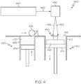
- FIG. 4 is a schematic view of a DMLF system 400 for manufacturing the one or more portions of the turbine component 200 of FIG. 2 in accordance with an exemplary embodiment.
- the system 400 includes a fabrication device 410, a powder delivery device 430, a scanner 440, and a laser 460 that function to manufacture the respective portion of an intermediate turbine component article 450 with build material 470.
- the first portion formed in step 320 is the blade portion.
- the fabrication device 410 includes a build container 412 with a fabrication support 414 on which the intermediate turbine component article 450 is formed and supported.
- the fabrication support 414 is movable within the build container 412 in a vertical direction and is adjusted in such a way to define a working plane 416.
- the delivery device 430 includes a powder chamber 432 with a delivery support 434 that supports the build material 470 and is also movable in the vertical direction.
- the delivery device 430 further includes a roller or wiper 436 that transfers build material 470 from the delivery device 430 to the fabrication device 410.
- a base block 445 may be installed on the fabrication support 414.
- the fabrication support 414 is lowered and the delivery support 434 is raised.
- the roller or wiper 436 scrapes or otherwise pushes a portion of the build material 470 from the delivery device 430 to form the working plane 416 in the fabrication device 410.
- the laser 460 emits a laser beam 462, which is directed by the scanner 440 onto the build material 470 in the working plane 416 to selectively fuse the build material 470 into a cross-sectional layer of the intermediate turbine component article 450 according to the design.
- the speed, position, and other operating parameters of the laser beam 462 are controlled to selectively fuse the powder of the build material 470 into larger structures by rapidly melting the powder particles that may melt or diffuse into the solid structure below, and subsequently, cool and resolidify.
- each layer of build material 470 will include unfused and fused build material 470 that respectively corresponds to the cross-sectional passages and walls that form the intermediate turbine component article 450.
- the laser beam 462 is relatively low power to selectively fuse the individual layer of build material 470.
- the laser beam 462 may have a power of approximately 50 to 500 Watts, although any suitable power may be provided.
- the fabrication support 414 Upon completion of a respective layer, the fabrication support 414 is lowered and the delivery support 434 is raised. Typically, the fabrication support 414, and thus the intermediate turbine component article 450, does not move in a horizontal plane during this step.
- the roller or wiper 436 again pushes a portion of the build material 470 from the delivery device 430 to form an additional layer of build material 470 on the working plane 416 of the fabrication device 410.
- the laser beam 462 is movably supported relative to the intermediate turbine component article 450 and is again controlled to selectively form another cross-sectional layer.
- the intermediate turbine component article 450 is positioned in a bed of build material 470 as the successive layers are formed such that the unfused and fused material supports subsequent layers. This process is continued according to the modeled design as successive cross-sectional layers are formed into the completed desired portion, e.g., the first portion of step 320.
- the delivery of build material 470 and movement of the intermediate turbine component article 450 in the vertical direction are relatively constant and only the movement of the laser beam 462 must be selectively controlled to provide a simpler and more precise implementation.
- the localized fusing of the build material 470 enables more precise placement of fused material to reduce or eliminate the occurrence of over-deposition of material and excessive energy or heat, which may otherwise result in cracking or distortion.
- the unused and unfused build material 470 may be reused, thereby further reducing scrap.
- the build material 470 may be formed by any suitable powder, including powdered metals, such as a stainless steel powder, and alloys and super alloy materials, such as nickel-based or cobalt superalloys.
- the build material 470 is a high temperature nickel base super alloy such as MAR-M-247, SC180, CMSX486, HON-4A, and Alloy10.
- IN718 or IN738 or other suitable alloys may be employed.
- the powder build material 470 may be selected for enhanced strength, durability, and useful life, particularly at high temperatures, although as described below, the powder build material 470 may also be selected based on the intended function of the area being formed. Each successive layer may be, for example, between 10 ⁇ m and 200 ⁇ m, although the thickness may be selected based on any number of parameters.
- the build material 470 may be selected based on the desired properties of the portion respectively being formed. For example, in step 320, if the first portion being formed is the blade portion 250, the build material 470 may be selected for stress rupture resistance properties, for example, SC180 and CMSX486.
- the first portion is removed from additive manufacturing system (e.g., from the DMLF system 400).
- the first portion formed in step 320 undergoes portion treatments.
- portion treatments of step 330 refer to intermediate processing treatments that may be suitable for the first portion but that may be unsuitable for portions formed in subsequent steps, e.g., because of the temperature or other processing requirements of the desired treatment.
- portion treatments may include, for example, solutioning, aging, annealing, quenching, peening, polishing, hot isostatic pressing (HIP), or coatings.
- the first portion may comprise a blade airfoil portion 250 fabricated from CMSX486.
- Portion treatments of step 330 may comprise stress relief, solutioning, high temperature aging, peening, HIP, and polishing.
- the portion treatment is a heat treatment.
- an alternate material or fabrication method may be employed which may result in different step 330 portion treatments for optimizing the component.
- a post-laser fusion process of step 330 is a HIP process in which an encapsulation layer is applied to the intermediate turbine component article and pressure and heat are applied to remove or reduce any porosity and cracks internal to or on the surface.
- the encapsulation layer functions to effectively convert any surface porosity and cracks into internal porosity and cracks, and after the application of pressure and heat, removes or reduces the porosity and cracks.
- Such encapsulation layers may be subsequently removed or maintained to function as an oxidation protection layer.
- the encapsulation layer may be a metal or alloy that is compatible with the substrate and may be applied by a plating or coating process, as described below.
- the HIP process may be performed at a processing temperature in a range of about 1000° C to about 1300° C and may be performed at a pressure in a range of about 1 ksi to about 25 ksi for a time period of about 1 to about 10 hours.
- the HIP processing temperature, pressure, and time may be smaller or larger to form a compacted solid having negligible porosity.
- step 340 a second portion is formed on the first portion.
- the second portion is formed by additive manufacturing techniques discussed above in reference to step 320.
- the intermediate turbine article 300 may be positioned within the DMLF system 400 described above and iterative layers of the second portion may be formed by depositing a build material 470 initially on the first portion and subsequently on the underlying layers of the second portion and selectively fusing the deposited material to form the second portion according to the model generated in step 310.
- the use of additive manufacturing to form a second portion on the first portion may be superior to the conventional bonding techniques, such as brazing and diffusion bonding with braze foils, since the additive manufacturing does not require the introduction of extraneous materials such as melting point suppressing elements like boron, silicon, or phosphorous which contaminate and complicate the metallography of the structural interface of the first portion to the second portion.
- the second portion is the tip portion 270 that is built on the blade portion 250. Since the tip portion 270 is formed in separate steps from the blade portion 250, the build material 470 of step 340 is different from the build material 470 of step 320.
- the build material 470 for the tip portion 270 may be selected for oxidation and TMF resistance properties, for example, using HON4A.
- the additive manufacturing technique of step 340 enables the second portion to be formed directly on the first portion with a different, optimized build material 470 such that the resulting structure, discussed below, may have portion-specific properties.
- the intermediate turbine article which now includes the first and second portions, is removed from additive manufacturing system (e.g., from the DMLF system 400).
- the intermediate turbine article undergoes additional portion treatments.
- the first and second portions of the intermediate component article are subjected to a heat treatment.
- the method 300 may proceed directly to step 360 and the portion treatments of step 350 may be omitted and/or incorporated into subsequent steps.
- the portion treatments of step 350 refer to treatments that may be suitable for the first and second portions but that may be unsuitable for portions formed in subsequent steps. Such treatments may include, for example, aging, annealing, quenching, peening, polishing, hot isostatic pressing (HIP), or coatings.
- step 360 a third portion is formed on the first portion.
- the third portion may be formed by additive manufacturing techniques discussed above in reference to step 320.
- the intermediate turbine article which initially includes the first and second portions, is positioned within the DMLF system 400 described above and iterative layers of the third portion may be formed by depositing a build material 470 initially on the first portion and subsequently on the underlying layers of the third portion and selectively fusing the deposited build material to form the third portion according to the model generated in step 310.
- the third portion is the attachment portion 290 that is built on the blade portion 250. Since the attachment portion 290 is formed in separate steps from the blade portion 250 and the tip portion 270, the build material 470 of step 360 is different from the build material 470 of step 320 or step 340. As an example, in step 360, the build material 470 for the attachment portion 290 may be selected for strength and fatigue resistance properties, such as Alloy 10. In some embodiments, not being part of the invention, step 360 may be omitted and the turbine component may only include two portions. Moreover, although not shown, the turbine component may include more than three portions and step 360 may be repeated with additional portions.
- the intermediate turbine article which now includes the first, second, and third portions, is removed from the additive manufacturing system (e.g., from the DMLF system 400).
- the intermediate turbine article undergoes finishing treatments.
- Such treatments may include, for example, aging, annealing, quenching, peening, polishing, hot isostatic pressing (HIP), or coatings.
- the intermediate turbine article may be machined to the final specifications to form the turbine component 200.
- the machining techniques may include, for example, the addition of a tip cap, machining of the dovetail, formation of cooling holes, and grinding the rotor tips.
- the intermediate turbine article may undergo optional coating operations such as oxidation, environmental, and thermal barrier coatings.
- the turbine component 200 may be tested and installed in a turbine section of a gas turbine engine, as shown in FIG. 1 .
- a turbine stator may include a single crystal nickel base superalloy airfoil with the primary and secondary crystallographic orientations oriented for optimal creep and thermo-mechanical fatigue resistance.
- the airfoil may be attached to an inner flow path hub made of a less expensive but high strength material such as Mar-M-247, and the airfoil may be attached to an outer flow path shroud made of Mar-M-247.
- other combinations of materials and crystallographic orientations may be employed to obtain an optimal component for the particular application.
- step 310 of method 300 includes creating a 3D solid design model of a multi-material turbine blade.
- step 320 may include forming first portion blade airfoil portion 250 from a cast SC180 single crystal nickel base superalloy that is crystallographically aligned to optimize stress rupture and thermo-mechanical fatigue properties.
- the portion treatments of step 330 may include solutioning, HIP, and aging processing to enhance stress rupture and fatigue properties.
- Step 340 may include the forming of a second portion turbine blade tip 270 from a nickel base superalloy HON-4A using DMLF additive manufacturing processes.
- processing portion treatment step 350 may include stress relief processing to eliminate thermal build stresses from the DMLF processing, peening of the blade tip 270 to reduce surface roughness, encapsulation and HIP to enhance metallography in the blade tip 270, and optional high temperature aging processing for optimal microstructure.
- Step 360 in this embodiment example may include utilizing DMLF additive manufacturing methods to form a third hub portion 290 from a nickel base superalloy Alloy 10 for superior strength and fatigue resistance in the blade dovetail region of the component.
- Step 370 may include stress relief processing to eliminate thermal build stresses from the DMLF processing, peening of the blade hub 290 to reduce surface roughness, encapsulation and HIP to enhance metallography in the blade hub 290, and potential thermal aging processing for optimal microstructure. Additional finishing treatment 370 may include machining the blade dovetail 222, machining the blade tip 212, final age heat treatments to the final component, oxidation and thermal barrier coatings, shot peening of the dovetail to induce compressive surface stresses for enhanced fatigue life, and other machining to satisfy the design requirements of the 3D solid design model of the component generated in step 310.
- the method 300 has been discussed above with reference to the formation of a single intermediate turbine article, and thus, a single turbine component. However, in one exemplary embodiment of the method 300, more than one intermediate turbine article may be manufactured simultaneously. Unless otherwise noted, method 300 in this embodiment proceeds as discussed above.
- the intermediate turbine articles are formed on a common base block (e.g., base block 445) to provide a common orientation and a known point of reference and formed as discussed above. Successive layers can be formed for the group of intermediate turbine articles simultaneously according to a common module or design. For example, the powdered metal may be deposited across a single working plane and one or more lasers may selectively fuse the layers of each intermediate turbine article, either sequentially or simultaneously. The intermediate turbine articles may then be lowered together for the formation of the next layer. Simultaneous fabrication of a number of components may minimize cost and variability of the manufacturing process.
- exemplary embodiments may enhance turbine components fabricated with additive manufacturing techniques, including DMLF.
- durability and life span of the turbine component may be improved by manufacturing each portion of the turbine component with the optimal material.
- rapid prototyping with additive manufacturing reduces costs and cycle time in the engine design, particularly in the iterative environment of engine design.
- exemplary embodiments may produce turbine components capable of withstanding higher temperatures and stresses, thereby leading to further improvements in engine performance.
- Exemplary embodiments are applicable to both commercial and military gas turbine engines and auxiliary power units, including industrial applications such as electricity generation, naval propulsion, pumping sets for gas and oil transmission, aircraft and/or spacecraft propulsion, automobile engines, and/or stationary power plants.
Landscapes
- Engineering & Computer Science (AREA)
- Chemical & Material Sciences (AREA)
- Manufacturing & Machinery (AREA)
- Mechanical Engineering (AREA)
- Materials Engineering (AREA)
- Physics & Mathematics (AREA)
- Composite Materials (AREA)
- Metallurgy (AREA)
- Organic Chemistry (AREA)
- Crystallography & Structural Chemistry (AREA)
- Thermal Sciences (AREA)
- Plasma & Fusion (AREA)
- Powder Metallurgy (AREA)
- Turbine Rotor Nozzle Sealing (AREA)
- Laser Beam Processing (AREA)
Claims (6)
- Procédé de fabrication d'un composant de moteur (200), comprenant les étapes suivantes :fourniture d'une première partie (250) d'un article de composant intermédiaire (450), la première partie (250) comprenant un premier matériau ;la soumission de la première partie (250) de l'article de composant intermédiaire (450) à un traitement thermique ;la formation, après l'étape de soumission, d'une deuxième partie (270) de l'article de composant intermédiaire (450) sur la première partie (250) de l'article de composant intermédiaire (450) à une technique de fabrication additive, la deuxième partie (270) comprenant un deuxième matériau ;la formation d'une troisième partie (290) de l'article de composant intermédiaire (450) sur la première partie (250) de l'article de composant intermédiaire (450), la troisième partie (290) comprenant un troisième matériau ; etla soumission des première et deuxième parties (250, 270) de l'article de composant intermédiaire (450) à un traitement thermique avant l'étape de formation de la troisième partie (290) de l'article de composant intermédiaire (450) ;l'achèvement de l'article de composant intermédiaire (450) pour former le composant de moteur (200) ; le composant de moteur (200) étant un composant de turbine (200) et l'étape de fourniture comprenant la fourniture d'une partie de pale (250) en tant que première partie (250), la formation de la deuxième partie (270) comprenant la fourniture d'une partie de pointe (270) en tant que deuxième partie (270), et la formation de la troisième partie (290) comprenant la fourniture d'une partie de fixation (290) en tant que troisième partie (290).
- Procédé selon la revendication 1, dans lequel l'étape de formation comprend la fusion laser directe de métaux de couches séquentielles de matériau de construction (470) donnant la deuxième partie (270).
- Procédé selon la revendication 1, dans lequel l'étape de formation comprend la formation de la deuxième partie (270) par fusion laser directe de métaux.
- Procédé selon la revendication 1, dans lequel l'étape de fourniture comprend la fourniture de la première partie (250) de sorte que le premier matériau soit un matériau monocristallin.
- Procédé selon la revendication 1, dans lequel l'étape de fourniture comprend la fourniture de la deuxième partie (270) de sorte que le deuxième matériau soit un superalliage à base de nickel pour haute température principalement durci par gamma prime.
- Procédé selon la revendication 5, dans lequel l'étape de fourniture comprend la fourniture de la troisième partie (290) de sorte que le troisième matériau soit un superalliage à base de nickel métallique de puissance, différent du deuxième matériau.
Applications Claiming Priority (1)
| Application Number | Priority Date | Filing Date | Title |
|---|---|---|---|
| US13/360,126 US9266170B2 (en) | 2012-01-27 | 2012-01-27 | Multi-material turbine components |
Publications (2)
| Publication Number | Publication Date |
|---|---|
| EP2620594A1 EP2620594A1 (fr) | 2013-07-31 |
| EP2620594B1 true EP2620594B1 (fr) | 2020-04-22 |
Family
ID=47598687
Family Applications (1)
| Application Number | Title | Priority Date | Filing Date |
|---|---|---|---|
| EP13151337.6A Not-in-force EP2620594B1 (fr) | 2012-01-27 | 2013-01-15 | Méthode de fabrication de composant de turbine à matériaux multiples |
Country Status (2)
| Country | Link |
|---|---|
| US (1) | US9266170B2 (fr) |
| EP (1) | EP2620594B1 (fr) |
Families Citing this family (48)
| Publication number | Priority date | Publication date | Assignee | Title |
|---|---|---|---|---|
| DE102011080187A1 (de) * | 2011-08-01 | 2013-02-07 | Siemens Aktiengesellschaft | Verfahren zum Erzeugen einer Schaufel für eine Strömungskraftmaschine und Schaufel für eine Strömungskraftmaschine |
| US10309232B2 (en) * | 2012-02-29 | 2019-06-04 | United Technologies Corporation | Gas turbine engine with stage dependent material selection for blades and disk |
| US9296039B2 (en) * | 2012-04-24 | 2016-03-29 | United Technologies Corporation | Gas turbine engine airfoil impingement cooling |
| US9074482B2 (en) * | 2012-04-24 | 2015-07-07 | United Technologies Corporation | Airfoil support method and apparatus |
| US10259043B2 (en) * | 2013-02-01 | 2019-04-16 | Aerojet Rocketdyne Of De, Inc. | Additive manufacturing for elevated-temperature ductility and stress rupture life |
| US10408061B2 (en) | 2013-03-15 | 2019-09-10 | United Technologies Corporation | Article with sections having different microstructures and method therefor |
| US9903212B2 (en) * | 2013-07-30 | 2018-02-27 | Siemens Aktiengesellschaft | Mechanical joining using additive manufacturing process |
| US10247003B2 (en) | 2013-09-26 | 2019-04-02 | United Technologies Corporation | Balanced rotating component for a gas powered engine |
| US20150086408A1 (en) * | 2013-09-26 | 2015-03-26 | General Electric Company | Method of manufacturing a component and thermal management process |
| EP3055605A4 (fr) * | 2013-10-07 | 2017-06-28 | United Technologies Corporation | Article comprenant une structure interne |
| EP3055091A4 (fr) | 2013-10-09 | 2017-07-05 | United Technologies Corporation | Composant de turbine à densités et propriétés multiples |
| WO2015119692A2 (fr) | 2013-11-14 | 2015-08-13 | General Electric Company | Fabrication en couches de composants en alliage monocristallin |
| US9932841B2 (en) | 2014-01-17 | 2018-04-03 | United Technologies Corporation | Workpiece manufactured from an additive manufacturing system having a particle separator and method of operation |
| WO2015112583A1 (fr) * | 2014-01-21 | 2015-07-30 | United Technologies Corporation | Procédé permettant de former des composants monocristallins à l'aide d'une fabrication additive et d'une refusion |
| EP3096908B1 (fr) * | 2014-01-24 | 2024-07-24 | RTX Corporation | Conditionnement d'un ou plusieurs objets de fabrication additive |
| US9868155B2 (en) * | 2014-03-20 | 2018-01-16 | Ingersoll-Rand Company | Monolithic shrouded impeller |
| US9896944B2 (en) | 2014-04-18 | 2018-02-20 | Siemens Energy, Inc. | Forming a secondary structure directly onto a turbine blade |
| US9333578B2 (en) | 2014-06-30 | 2016-05-10 | General Electric Company | Fiber reinforced brazed components and methods |
| US9757802B2 (en) | 2014-06-30 | 2017-09-12 | General Electric Company | Additive manufacturing methods and systems with fiber reinforcement |
| EP3206816B2 (fr) * | 2014-11-21 | 2024-10-09 | Siemens Energy Global GmbH & Co. KG | Procédé de fabrication d'un élément et élément |
| US9757936B2 (en) | 2014-12-29 | 2017-09-12 | General Electric Company | Hot gas path component |
| US20160279734A1 (en) * | 2015-03-27 | 2016-09-29 | General Electric Company | Component and method for fabricating a component |
| FR3035605B1 (fr) * | 2015-04-28 | 2021-08-27 | Alain Toufine | Procede d'obtention de poutre tubulaire creuse raidie en flexion, torsion et compression / flambement et ame de poutre et extremites de poutre obtenues par fusion de poudres et gradients metallurgiques |
| WO2016184685A1 (fr) * | 2015-05-20 | 2016-11-24 | Man Diesel & Turbo Se | Procédé de fabrication d'un rotor de turbomachine |
| DE102015210744A1 (de) * | 2015-06-12 | 2016-12-15 | Siemens Aktiengesellschaft | Verfahren zum Fertigen einer Turbinenschaufel |
| GB201514801D0 (en) * | 2015-08-20 | 2015-10-07 | Rolls Royce Plc And Rolls Royce Deutschland Ltd & Co Kg | Method of manufacture of a turbine component |
| US10343392B2 (en) | 2015-08-27 | 2019-07-09 | General Electric Company | Powder-bed additive manufacturing devices and methods |
| US10010937B2 (en) | 2015-11-09 | 2018-07-03 | General Electric Company | Additive manufacturing method for making overhanging tabs in cooling holes |
| US10487664B2 (en) | 2015-11-09 | 2019-11-26 | General Electric Company | Additive manufacturing method for making holes bounded by thin walls in turbine components |
| US10350684B2 (en) | 2015-11-10 | 2019-07-16 | General Electric Company | Additive manufacturing method for making complex film holes |
| US10378087B2 (en) | 2015-12-09 | 2019-08-13 | General Electric Company | Nickel base super alloys and methods of making the same |
| EP3205442A1 (fr) * | 2016-02-12 | 2017-08-16 | Siemens Aktiengesellschaft | Pale de turbine à gaz et son procédé de fabrication |
| DE102016203785A1 (de) * | 2016-03-08 | 2017-09-14 | MTU Aero Engines AG | Verfahren zum Herstellen einer Schaufel für eine Strömungsmaschine |
| EP3219921B1 (fr) * | 2016-03-16 | 2020-04-29 | MTU Aero Engines GmbH | Aube directrice reglable de turbomachines, turbo-machine et méthode de fabrication |
| EP3238863A1 (fr) * | 2016-04-27 | 2017-11-01 | MTU Aero Engines GmbH | Procédé de fabrication d'une aube de turbomachine |
| US20180141127A1 (en) * | 2016-11-21 | 2018-05-24 | Pratt & Whitney Canada Corp. | Method of manufacturing a component with passages |
| DE102016223731A1 (de) * | 2016-11-30 | 2018-05-30 | MTU Aero Engines AG | Verfahren zum Herstellen einer Schaufel für eine Strömungsmaschine |
| US10583530B2 (en) | 2017-01-09 | 2020-03-10 | General Electric Company | System and methods for fabricating a component with laser array |
| US10995619B2 (en) | 2017-05-26 | 2021-05-04 | General Electric Company | Airfoil and method of fabricating same |
| US11027368B2 (en) | 2017-08-02 | 2021-06-08 | General Electric Company | Continuous additive manufacture of high pressure turbine |
| DE102017215321A1 (de) * | 2017-09-01 | 2019-03-07 | MTU Aero Engines AG | Verfahren zur herstellung eines titanaluminid - bauteils mit zähem kern und entsprechend hergestelltes bauteil |
| EP3459653A1 (fr) * | 2017-09-20 | 2019-03-27 | Siemens Aktiengesellschaft | Procédé de fabrication d'un composant et composant |
| US11092203B2 (en) * | 2018-04-25 | 2021-08-17 | Goodrich Corporation | Hybrid torque bar |
| US11033992B2 (en) * | 2018-10-05 | 2021-06-15 | Pratt & Whitney Canada Corp. | Double row compressor stators |
| US10577679B1 (en) | 2018-12-04 | 2020-03-03 | General Electric Company | Gamma prime strengthened nickel superalloy for additive manufacturing |
| FR3102378B1 (fr) | 2019-10-23 | 2021-11-12 | Safran Aircraft Engines | Procédé de fabrication d’une aube en matériau composite avec bord d’attaque métallique rapporté |
| EP4461927A1 (fr) * | 2023-05-12 | 2024-11-13 | Doosan Enerbility Co., Ltd. | Corps d'écoulement pour turbine à gaz, turbine à gaz, procédé de fabrication d'un corps d'écoulement pour turbine à gaz et procédé de réparation d'un corps d'écoulement d'une turbine à gaz |
| US12253003B1 (en) * | 2023-08-21 | 2025-03-18 | Rtx Corporation | Integral stator vane weld shield |
Family Cites Families (80)
| Publication number | Priority date | Publication date | Assignee | Title |
|---|---|---|---|---|
| USRE31339E (en) | 1977-08-03 | 1983-08-09 | Howmet Turbine Components Corporation | Process for producing elevated temperature corrosion resistant metal articles |
| US4145481A (en) | 1977-08-03 | 1979-03-20 | Howmet Turbine Components Corporation | Process for producing elevated temperature corrosion resistant metal articles |
| US4198442A (en) | 1977-10-31 | 1980-04-15 | Howmet Turbine Components Corporation | Method for producing elevated temperature corrosion resistant articles |
| DE3067748D1 (en) | 1979-07-30 | 1984-06-14 | Secr Defence Brit | A method of forming a corrosion resistant coating on a metal article |
| US5128179A (en) | 1981-07-08 | 1992-07-07 | Alloy Surfaces Company, Inc. | Metal diffusion and after-treatment |
| US4499048A (en) | 1983-02-23 | 1985-02-12 | Metal Alloys, Inc. | Method of consolidating a metallic body |
| SE8401757L (sv) | 1984-03-30 | 1985-10-01 | Yngve Lindblom | Metalloxidkeramiska ytskikt pa hog temperaturmaterial |
| US5514482A (en) | 1984-04-25 | 1996-05-07 | Alliedsignal Inc. | Thermal barrier coating system for superalloy components |
| US4818562A (en) | 1987-03-04 | 1989-04-04 | Westinghouse Electric Corp. | Casting shapes |
| US5096518A (en) | 1989-02-22 | 1992-03-17 | Kabushiki Kaisha Kobe Seiko Sho | Method for encapsulating material to be processed by hot or warm isostatic pressing |
| US5106266A (en) | 1989-07-25 | 1992-04-21 | Allied-Signal Inc. | Dual alloy turbine blade |
| CA2060520A1 (fr) | 1991-03-11 | 1994-12-09 | Jonathan G. Storer | Materiaux composites a matrice metallique |
| US5236116A (en) | 1991-08-26 | 1993-08-17 | The Pullman Company | Hardfaced article and process to provide porosity free hardfaced coating |
| JPH05104259A (ja) | 1991-10-17 | 1993-04-27 | Mitsubishi Heavy Ind Ltd | 拡散接合法 |
| US5249785A (en) | 1992-04-20 | 1993-10-05 | Boeing Commercial Airplane Group | Reconfigurable holding fixture |
| US5554837A (en) | 1993-09-03 | 1996-09-10 | Chromalloy Gas Turbine Corporation | Interactive laser welding at elevated temperatures of superalloy articles |
| US20030088980A1 (en) | 1993-11-01 | 2003-05-15 | Arnold James E. | Method for correcting defects in a workpiece |
| US5465780A (en) | 1993-11-23 | 1995-11-14 | Alliedsignal Inc. | Laser machining of ceramic cores |
| US5650235A (en) | 1994-02-28 | 1997-07-22 | Sermatech International, Inc. | Platinum enriched, silicon-modified corrosion resistant aluminide coating |
| US5634992A (en) | 1994-06-20 | 1997-06-03 | General Electric Company | Method for heat treating gamma titanium aluminide alloys |
| US5837960A (en) * | 1995-08-14 | 1998-11-17 | The Regents Of The University Of California | Laser production of articles from powders |
| US5745834A (en) | 1995-09-19 | 1998-04-28 | Rockwell International Corporation | Free form fabrication of metallic components |
| JP3070957B2 (ja) | 1995-11-08 | 2000-07-31 | シチズン時計株式会社 | 表面硬化チタン材料およびチタン材料の表面硬化方法 |
| US5640667A (en) | 1995-11-27 | 1997-06-17 | Board Of Regents, The University Of Texas System | Laser-directed fabrication of full-density metal articles using hot isostatic processing |
| US6049978A (en) | 1996-12-23 | 2000-04-18 | Recast Airfoil Group | Methods for repairing and reclassifying gas turbine engine airfoil parts |
| US6036995A (en) | 1997-01-31 | 2000-03-14 | Sermatech International, Inc. | Method for removal of surface layers of metallic coatings |
| US6355086B2 (en) * | 1997-08-12 | 2002-03-12 | Rolls-Royce Corporation | Method and apparatus for making components by direct laser processing |
| US6174448B1 (en) | 1998-03-02 | 2001-01-16 | General Electric Company | Method for stripping aluminum from a diffusion coating |
| US6485848B1 (en) | 1998-04-27 | 2002-11-26 | General Electric Company | Coated article and method of making |
| US6172327B1 (en) | 1998-07-14 | 2001-01-09 | General Electric Company | Method for laser twist welding of compressor blisk airfoils |
| US5947179A (en) | 1998-07-30 | 1999-09-07 | Ford Motor Company | Sprayforming bulk deposits of allotropic metal |
| US6269540B1 (en) * | 1998-10-05 | 2001-08-07 | National Research Council Of Canada | Process for manufacturing or repairing turbine engine or compressor components |
| GB9821748D0 (en) | 1998-10-07 | 1998-12-02 | Rolls Royce Plc | A titanium article having a protective coating and a method of applying a protective coating to a titanium article |
| US6811744B2 (en) * | 1999-07-07 | 2004-11-02 | Optomec Design Company | Forming structures from CAD solid models |
| US6154959A (en) | 1999-08-16 | 2000-12-05 | Chromalloy Gas Turbine Corporation | Laser cladding a turbine engine vane platform |
| US6504127B1 (en) | 1999-09-30 | 2003-01-07 | National Research Council Of Canada | Laser consolidation methodology and apparatus for manufacturing precise structures |
| US6355116B1 (en) | 2000-03-24 | 2002-03-12 | General Electric Company | Method for renewing diffusion coatings on superalloy substrates |
| US6568077B1 (en) | 2000-05-11 | 2003-05-27 | General Electric Company | Blisk weld repair |
| AU2001275164A1 (en) | 2000-06-01 | 2001-12-11 | Board Of Regents, The University Of Texas System | Direct selective laser sintering of metals |
| US6575349B2 (en) | 2001-02-22 | 2003-06-10 | Hickham Industries, Inc. | Method of applying braze materials to a substrate |
| US7204019B2 (en) | 2001-08-23 | 2007-04-17 | United Technologies Corporation | Method for repairing an apertured gas turbine component |
| US6758914B2 (en) | 2001-10-25 | 2004-07-06 | General Electric Company | Process for partial stripping of diffusion aluminide coatings from metal substrates, and related compositions |
| RU2333086C2 (ru) | 2002-01-24 | 2008-09-10 | Х.Ц. Щтарк, Инк. | Очищенный лазерной обработкой и плавлением тугоплавкий металл и его сплав |
| US6998151B2 (en) | 2002-05-10 | 2006-02-14 | General Electric Company | Method for applying a NiAl based coating by an electroplating technique |
| US6902656B2 (en) | 2002-05-24 | 2005-06-07 | Dalsa Semiconductor Inc. | Fabrication of microstructures with vacuum-sealed cavity |
| US6890831B2 (en) | 2002-06-03 | 2005-05-10 | Sanyo Electric Co., Ltd. | Method of fabricating semiconductor device |
| EP1400339A1 (fr) | 2002-09-17 | 2004-03-24 | Siemens Aktiengesellschaft | Procédé pour la fabrication d'un article tridimensionnel |
| US6969457B2 (en) | 2002-10-21 | 2005-11-29 | General Electric Company | Method for partially stripping a coating from the surface of a substrate, and related articles and compositions |
| US6884461B2 (en) | 2002-12-20 | 2005-04-26 | General Electric Company | Turbine nozzle with heat rejection coats |
| US7008553B2 (en) | 2003-01-09 | 2006-03-07 | General Electric Company | Method for removing aluminide coating from metal substrate and turbine engine part so treated |
| US7216428B2 (en) | 2003-03-03 | 2007-05-15 | United Technologies Corporation | Method for turbine element repairing |
| DE10319494A1 (de) | 2003-04-30 | 2004-11-18 | Mtu Aero Engines Gmbh | Verfahren zur Reparatur und/oder Modifikation von Bauteilen einer Gasturbine |
| US6838191B1 (en) | 2003-05-20 | 2005-01-04 | The United States Of America As Represented By The Admistrator Of The National Aeronautics And Space Administration | Blanch resistant and thermal barrier NiAl coating systems for advanced copper alloys |
| US20050036892A1 (en) | 2003-08-15 | 2005-02-17 | Richard Bajan | Method for applying metallurgical coatings to gas turbine components |
| US20050091848A1 (en) | 2003-11-03 | 2005-05-05 | Nenov Krassimir P. | Turbine blade and a method of manufacturing and repairing a turbine blade |
| GB0408164D0 (en) | 2004-04-13 | 2004-05-19 | Immune Targeting Systems Ltd | Antigen delivery vectors and constructs |
| DE102004045049A1 (de) | 2004-09-15 | 2006-03-16 | Man Turbo Ag | Verfahren zum Aufbringen einer Schutzschicht |
| GB2418208B (en) | 2004-09-18 | 2007-06-06 | Rolls Royce Plc | Component coating |
| US9997338B2 (en) | 2005-03-24 | 2018-06-12 | Oerlikon Surface Solutions Ag, Pfäffikon | Method for operating a pulsed arc source |
| US20060222776A1 (en) | 2005-03-29 | 2006-10-05 | Honeywell International, Inc. | Environment-resistant platinum aluminide coatings, and methods of applying the same onto turbine components |
| US7923127B2 (en) | 2005-11-09 | 2011-04-12 | United Technologies Corporation | Direct rolling of cast gamma titanium aluminide alloys |
| US20070141375A1 (en) | 2005-12-20 | 2007-06-21 | Budinger David E | Braze cladding for direct metal laser sintered materials |
| US7829142B2 (en) | 2006-06-21 | 2010-11-09 | General Electric Company | Method for aluminizing serpentine cooling passages of jet engine blades |
| ES2381854T3 (es) | 2006-07-14 | 2012-06-01 | Avioprop S.r.l. | Producción en serie de artículos tridimensionales hechos de compuestos intermetálicos |
| DE102006044555A1 (de) | 2006-09-21 | 2008-04-03 | Mtu Aero Engines Gmbh | Reparaturverfahren |
| DE102006049219A1 (de) | 2006-10-18 | 2008-04-30 | Mtu Aero Engines Gmbh | Hochdruckturbinen-Schaufel und Verfahren zur Reparatur von Hochdruckturbinen-Schaufeln |
| GB0709838D0 (en) | 2007-05-23 | 2007-07-04 | Rolls Royce Plc | A hollow blade and a method of manufacturing a hollow blade |
| GB2449862B (en) | 2007-06-05 | 2009-09-16 | Rolls Royce Plc | Method for producing abrasive tips for gas turbine blades |
| US20100025001A1 (en) | 2007-06-25 | 2010-02-04 | Ching-Pang Lee | Methods for fabricating gas turbine components using an integrated disposable core and shell die |
| US20090081066A1 (en) * | 2007-09-26 | 2009-03-26 | Materials Solutions | Method of forming an article |
| GB0719195D0 (en) | 2007-10-02 | 2007-11-14 | Rolls Royce Plc | A nickel base superalloy |
| US10092975B2 (en) | 2008-02-12 | 2018-10-09 | United Technologies Corporation | Solid state additive manufacturing system |
| US8061142B2 (en) | 2008-04-11 | 2011-11-22 | General Electric Company | Mixer for a combustor |
| DE102008056336A1 (de) | 2008-11-07 | 2010-05-12 | Mtu Aero Engines Gmbh | Reparaturverfahren |
| US20100200189A1 (en) | 2009-02-12 | 2010-08-12 | General Electric Company | Method of fabricating turbine airfoils and tip structures therefor |
| EP2319641B1 (fr) | 2009-10-30 | 2017-07-19 | Ansaldo Energia IP UK Limited | Procédé pour appliquer plusieurs matériaux par fonte sélective au laser sur un article en 3D |
| US8728388B2 (en) | 2009-12-04 | 2014-05-20 | Honeywell International Inc. | Method of fabricating turbine components for engines |
| US9175568B2 (en) | 2010-06-22 | 2015-11-03 | Honeywell International Inc. | Methods for manufacturing turbine components |
| US8668442B2 (en) | 2010-06-30 | 2014-03-11 | Honeywell International Inc. | Turbine nozzles and methods of manufacturing the same |
| US20120034101A1 (en) * | 2010-08-09 | 2012-02-09 | James Allister W | Turbine blade squealer tip |
-
2012
- 2012-01-27 US US13/360,126 patent/US9266170B2/en active Active
-
2013
- 2013-01-15 EP EP13151337.6A patent/EP2620594B1/fr not_active Not-in-force
Non-Patent Citations (1)
| Title |
|---|
| None * |
Also Published As
| Publication number | Publication date |
|---|---|
| EP2620594A1 (fr) | 2013-07-31 |
| US20130195673A1 (en) | 2013-08-01 |
| US9266170B2 (en) | 2016-02-23 |
Similar Documents
| Publication | Publication Date | Title |
|---|---|---|
| EP2620594B1 (fr) | Méthode de fabrication de composant de turbine à matériaux multiples | |
| EP2540419B1 (fr) | Procédés de fabrication de composants de moteur avec dispositifs de pont structurel | |
| EP2495397B1 (fr) | Procédés pour réparer des composants de turbine | |
| EP2708296B1 (fr) | Procédés de fabrication d'ensembles de surfaces portantes de stator de turbine par méthodes de fabrication additive | |
| US9175568B2 (en) | Methods for manufacturing turbine components | |
| EP2754515B1 (fr) | Procédés de fabrication de composants de moteur à turbine à gaz utiilisant des techniques de fabrication additives | |
| EP3702069B1 (fr) | Composants d'aluminure de titane à partir d'articles formés par un processus de consolidation | |
| EP2570595B1 (fr) | Procédés de fabrication de composants à partir d'articles formés par des processus de fabrication additive | |
| EP3290135B1 (fr) | Procédés pour directionnellement recristalliser additively-manufactured d'articles métalliques par traitement thermique avec un four à gradient | |
| US20120003086A1 (en) | Turbine nozzles and methods of manufacturing the same | |
| EP3241634B1 (fr) | Procédé de fabrication d'un composant ayant une microstructure solidifieé directionnellement ou une mictrostructure monocristalline | |
| US9903214B2 (en) | Internally cooled turbine blisk and method of manufacture | |
| WO2017222920A1 (fr) | Procédés de réparation de trous de film dans une surface | |
| EP3475531B1 (fr) | Procédé de réparation d'un bord de fuite d'un profil aérodynamique d'une turbine à gaz | |
| EP3475533A1 (fr) | Procédés de réparation d'élément endommagé de moteur |
Legal Events
| Date | Code | Title | Description |
|---|---|---|---|
| PUAI | Public reference made under article 153(3) epc to a published international application that has entered the european phase |
Free format text: ORIGINAL CODE: 0009012 |
|
| 17P | Request for examination filed |
Effective date: 20130115 |
|
| AK | Designated contracting states |
Kind code of ref document: A1 Designated state(s): AL AT BE BG CH CY CZ DE DK EE ES FI FR GB GR HR HU IE IS IT LI LT LU LV MC MK MT NL NO PL PT RO RS SE SI SK SM TR |
|
| AX | Request for extension of the european patent |
Extension state: BA ME |
|
| RAP1 | Party data changed (applicant data changed or rights of an application transferred) |
Owner name: HONEYWELL INTERNATIONAL INC. |
|
| RIC1 | Information provided on ipc code assigned before grant |
Ipc: B33Y 80/00 20150101ALI20181116BHEP Ipc: F01D 5/28 20060101AFI20181116BHEP Ipc: B33Y 10/00 20150101ALI20181116BHEP Ipc: C30B 29/52 20060101ALI20181116BHEP Ipc: B22F 3/105 20060101ALI20181116BHEP Ipc: B22F 7/06 20060101ALI20181116BHEP Ipc: B22F 5/04 20060101ALI20181116BHEP Ipc: B22F 5/00 20060101ALI20181116BHEP Ipc: C30B 11/00 20060101ALI20181116BHEP Ipc: B23P 15/04 20060101ALI20181116BHEP |
|
| STAA | Information on the status of an ep patent application or granted ep patent |
Free format text: STATUS: EXAMINATION IS IN PROGRESS |
|
| GRAP | Despatch of communication of intention to grant a patent |
Free format text: ORIGINAL CODE: EPIDOSNIGR1 |
|
| STAA | Information on the status of an ep patent application or granted ep patent |
Free format text: STATUS: GRANT OF PATENT IS INTENDED |
|
| INTG | Intention to grant announced |
Effective date: 20191216 |
|
| GRAS | Grant fee paid |
Free format text: ORIGINAL CODE: EPIDOSNIGR3 |
|
| GRAA | (expected) grant |
Free format text: ORIGINAL CODE: 0009210 |
|
| STAA | Information on the status of an ep patent application or granted ep patent |
Free format text: STATUS: THE PATENT HAS BEEN GRANTED |
|
| AK | Designated contracting states |
Kind code of ref document: B1 Designated state(s): AL AT BE BG CH CY CZ DE DK EE ES FI FR GB GR HR HU IE IS IT LI LT LU LV MC MK MT NL NO PL PT RO RS SE SI SK SM TR |
|
| REG | Reference to a national code |
Ref country code: GB Ref legal event code: FG4D |
|
| REG | Reference to a national code |
Ref country code: CH Ref legal event code: EP |
|
| REG | Reference to a national code |
Ref country code: DE Ref legal event code: R096 Ref document number: 602013068089 Country of ref document: DE |
|
| REG | Reference to a national code |
Ref country code: IE Ref legal event code: FG4D |
|
| REG | Reference to a national code |
Ref country code: AT Ref legal event code: REF Ref document number: 1260329 Country of ref document: AT Kind code of ref document: T Effective date: 20200515 |
|
| REG | Reference to a national code |
Ref country code: LT Ref legal event code: MG4D |
|
| REG | Reference to a national code |
Ref country code: NL Ref legal event code: MP Effective date: 20200422 |
|
| PG25 | Lapsed in a contracting state [announced via postgrant information from national office to epo] |
Ref country code: NL Free format text: LAPSE BECAUSE OF FAILURE TO SUBMIT A TRANSLATION OF THE DESCRIPTION OR TO PAY THE FEE WITHIN THE PRESCRIBED TIME-LIMIT Effective date: 20200422 Ref country code: PT Free format text: LAPSE BECAUSE OF FAILURE TO SUBMIT A TRANSLATION OF THE DESCRIPTION OR TO PAY THE FEE WITHIN THE PRESCRIBED TIME-LIMIT Effective date: 20200824 Ref country code: LT Free format text: LAPSE BECAUSE OF FAILURE TO SUBMIT A TRANSLATION OF THE DESCRIPTION OR TO PAY THE FEE WITHIN THE PRESCRIBED TIME-LIMIT Effective date: 20200422 Ref country code: FI Free format text: LAPSE BECAUSE OF FAILURE TO SUBMIT A TRANSLATION OF THE DESCRIPTION OR TO PAY THE FEE WITHIN THE PRESCRIBED TIME-LIMIT Effective date: 20200422 Ref country code: NO Free format text: LAPSE BECAUSE OF FAILURE TO SUBMIT A TRANSLATION OF THE DESCRIPTION OR TO PAY THE FEE WITHIN THE PRESCRIBED TIME-LIMIT Effective date: 20200722 Ref country code: GR Free format text: LAPSE BECAUSE OF FAILURE TO SUBMIT A TRANSLATION OF THE DESCRIPTION OR TO PAY THE FEE WITHIN THE PRESCRIBED TIME-LIMIT Effective date: 20200723 Ref country code: IS Free format text: LAPSE BECAUSE OF FAILURE TO SUBMIT A TRANSLATION OF THE DESCRIPTION OR TO PAY THE FEE WITHIN THE PRESCRIBED TIME-LIMIT Effective date: 20200822 Ref country code: SE Free format text: LAPSE BECAUSE OF FAILURE TO SUBMIT A TRANSLATION OF THE DESCRIPTION OR TO PAY THE FEE WITHIN THE PRESCRIBED TIME-LIMIT Effective date: 20200422 |
|
| REG | Reference to a national code |
Ref country code: AT Ref legal event code: MK05 Ref document number: 1260329 Country of ref document: AT Kind code of ref document: T Effective date: 20200422 |
|
| PG25 | Lapsed in a contracting state [announced via postgrant information from national office to epo] |
Ref country code: BG Free format text: LAPSE BECAUSE OF FAILURE TO SUBMIT A TRANSLATION OF THE DESCRIPTION OR TO PAY THE FEE WITHIN THE PRESCRIBED TIME-LIMIT Effective date: 20200722 Ref country code: HR Free format text: LAPSE BECAUSE OF FAILURE TO SUBMIT A TRANSLATION OF THE DESCRIPTION OR TO PAY THE FEE WITHIN THE PRESCRIBED TIME-LIMIT Effective date: 20200422 Ref country code: RS Free format text: LAPSE BECAUSE OF FAILURE TO SUBMIT A TRANSLATION OF THE DESCRIPTION OR TO PAY THE FEE WITHIN THE PRESCRIBED TIME-LIMIT Effective date: 20200422 Ref country code: LV Free format text: LAPSE BECAUSE OF FAILURE TO SUBMIT A TRANSLATION OF THE DESCRIPTION OR TO PAY THE FEE WITHIN THE PRESCRIBED TIME-LIMIT Effective date: 20200422 |
|
| PG25 | Lapsed in a contracting state [announced via postgrant information from national office to epo] |
Ref country code: AL Free format text: LAPSE BECAUSE OF FAILURE TO SUBMIT A TRANSLATION OF THE DESCRIPTION OR TO PAY THE FEE WITHIN THE PRESCRIBED TIME-LIMIT Effective date: 20200422 |
|
| REG | Reference to a national code |
Ref country code: DE Ref legal event code: R097 Ref document number: 602013068089 Country of ref document: DE |
|
| PG25 | Lapsed in a contracting state [announced via postgrant information from national office to epo] |
Ref country code: RO Free format text: LAPSE BECAUSE OF FAILURE TO SUBMIT A TRANSLATION OF THE DESCRIPTION OR TO PAY THE FEE WITHIN THE PRESCRIBED TIME-LIMIT Effective date: 20200422 Ref country code: CZ Free format text: LAPSE BECAUSE OF FAILURE TO SUBMIT A TRANSLATION OF THE DESCRIPTION OR TO PAY THE FEE WITHIN THE PRESCRIBED TIME-LIMIT Effective date: 20200422 Ref country code: AT Free format text: LAPSE BECAUSE OF FAILURE TO SUBMIT A TRANSLATION OF THE DESCRIPTION OR TO PAY THE FEE WITHIN THE PRESCRIBED TIME-LIMIT Effective date: 20200422 Ref country code: ES Free format text: LAPSE BECAUSE OF FAILURE TO SUBMIT A TRANSLATION OF THE DESCRIPTION OR TO PAY THE FEE WITHIN THE PRESCRIBED TIME-LIMIT Effective date: 20200422 Ref country code: DK Free format text: LAPSE BECAUSE OF FAILURE TO SUBMIT A TRANSLATION OF THE DESCRIPTION OR TO PAY THE FEE WITHIN THE PRESCRIBED TIME-LIMIT Effective date: 20200422 Ref country code: EE Free format text: LAPSE BECAUSE OF FAILURE TO SUBMIT A TRANSLATION OF THE DESCRIPTION OR TO PAY THE FEE WITHIN THE PRESCRIBED TIME-LIMIT Effective date: 20200422 Ref country code: SM Free format text: LAPSE BECAUSE OF FAILURE TO SUBMIT A TRANSLATION OF THE DESCRIPTION OR TO PAY THE FEE WITHIN THE PRESCRIBED TIME-LIMIT Effective date: 20200422 Ref country code: IT Free format text: LAPSE BECAUSE OF FAILURE TO SUBMIT A TRANSLATION OF THE DESCRIPTION OR TO PAY THE FEE WITHIN THE PRESCRIBED TIME-LIMIT Effective date: 20200422 |
|
| PG25 | Lapsed in a contracting state [announced via postgrant information from national office to epo] |
Ref country code: PL Free format text: LAPSE BECAUSE OF FAILURE TO SUBMIT A TRANSLATION OF THE DESCRIPTION OR TO PAY THE FEE WITHIN THE PRESCRIBED TIME-LIMIT Effective date: 20200422 Ref country code: SK Free format text: LAPSE BECAUSE OF FAILURE TO SUBMIT A TRANSLATION OF THE DESCRIPTION OR TO PAY THE FEE WITHIN THE PRESCRIBED TIME-LIMIT Effective date: 20200422 |
|
| PLBE | No opposition filed within time limit |
Free format text: ORIGINAL CODE: 0009261 |
|
| STAA | Information on the status of an ep patent application or granted ep patent |
Free format text: STATUS: NO OPPOSITION FILED WITHIN TIME LIMIT |
|
| 26N | No opposition filed |
Effective date: 20210125 |
|
| PG25 | Lapsed in a contracting state [announced via postgrant information from national office to epo] |
Ref country code: SI Free format text: LAPSE BECAUSE OF FAILURE TO SUBMIT A TRANSLATION OF THE DESCRIPTION OR TO PAY THE FEE WITHIN THE PRESCRIBED TIME-LIMIT Effective date: 20200422 |
|
| PG25 | Lapsed in a contracting state [announced via postgrant information from national office to epo] |
Ref country code: MC Free format text: LAPSE BECAUSE OF FAILURE TO SUBMIT A TRANSLATION OF THE DESCRIPTION OR TO PAY THE FEE WITHIN THE PRESCRIBED TIME-LIMIT Effective date: 20200422 |
|
| REG | Reference to a national code |
Ref country code: CH Ref legal event code: PL |
|
| GBPC | Gb: european patent ceased through non-payment of renewal fee |
Effective date: 20210115 |
|
| PG25 | Lapsed in a contracting state [announced via postgrant information from national office to epo] |
Ref country code: LU Free format text: LAPSE BECAUSE OF NON-PAYMENT OF DUE FEES Effective date: 20210115 |
|
| REG | Reference to a national code |
Ref country code: BE Ref legal event code: MM Effective date: 20210131 |
|
| PG25 | Lapsed in a contracting state [announced via postgrant information from national office to epo] |
Ref country code: FR Free format text: LAPSE BECAUSE OF NON-PAYMENT OF DUE FEES Effective date: 20210131 |
|
| PG25 | Lapsed in a contracting state [announced via postgrant information from national office to epo] |
Ref country code: LI Free format text: LAPSE BECAUSE OF NON-PAYMENT OF DUE FEES Effective date: 20210131 Ref country code: CH Free format text: LAPSE BECAUSE OF NON-PAYMENT OF DUE FEES Effective date: 20210131 Ref country code: GB Free format text: LAPSE BECAUSE OF NON-PAYMENT OF DUE FEES Effective date: 20210115 |
|
| PG25 | Lapsed in a contracting state [announced via postgrant information from national office to epo] |
Ref country code: IE Free format text: LAPSE BECAUSE OF NON-PAYMENT OF DUE FEES Effective date: 20210115 |
|
| PG25 | Lapsed in a contracting state [announced via postgrant information from national office to epo] |
Ref country code: BE Free format text: LAPSE BECAUSE OF NON-PAYMENT OF DUE FEES Effective date: 20210131 |
|
| PG25 | Lapsed in a contracting state [announced via postgrant information from national office to epo] |
Ref country code: HU Free format text: LAPSE BECAUSE OF FAILURE TO SUBMIT A TRANSLATION OF THE DESCRIPTION OR TO PAY THE FEE WITHIN THE PRESCRIBED TIME-LIMIT; INVALID AB INITIO Effective date: 20130115 |
|
| PG25 | Lapsed in a contracting state [announced via postgrant information from national office to epo] |
Ref country code: CY Free format text: LAPSE BECAUSE OF FAILURE TO SUBMIT A TRANSLATION OF THE DESCRIPTION OR TO PAY THE FEE WITHIN THE PRESCRIBED TIME-LIMIT Effective date: 20200422 |
|
| P01 | Opt-out of the competence of the unified patent court (upc) registered |
Effective date: 20230525 |
|
| PG25 | Lapsed in a contracting state [announced via postgrant information from national office to epo] |
Ref country code: MK Free format text: LAPSE BECAUSE OF FAILURE TO SUBMIT A TRANSLATION OF THE DESCRIPTION OR TO PAY THE FEE WITHIN THE PRESCRIBED TIME-LIMIT Effective date: 20200422 |
|
| PGFP | Annual fee paid to national office [announced via postgrant information from national office to epo] |
Ref country code: DE Payment date: 20240129 Year of fee payment: 12 |
|
| PG25 | Lapsed in a contracting state [announced via postgrant information from national office to epo] |
Ref country code: TR Free format text: LAPSE BECAUSE OF FAILURE TO SUBMIT A TRANSLATION OF THE DESCRIPTION OR TO PAY THE FEE WITHIN THE PRESCRIBED TIME-LIMIT Effective date: 20200422 |
|
| PG25 | Lapsed in a contracting state [announced via postgrant information from national office to epo] |
Ref country code: MT Free format text: LAPSE BECAUSE OF FAILURE TO SUBMIT A TRANSLATION OF THE DESCRIPTION OR TO PAY THE FEE WITHIN THE PRESCRIBED TIME-LIMIT Effective date: 20200422 |
|
| REG | Reference to a national code |
Ref country code: DE Ref legal event code: R119 Ref document number: 602013068089 Country of ref document: DE |
|
| PG25 | Lapsed in a contracting state [announced via postgrant information from national office to epo] |
Ref country code: DE Free format text: LAPSE BECAUSE OF NON-PAYMENT OF DUE FEES Effective date: 20250801 |