EP2620656A2 - Load-Sensing-Ventilbaugruppe mit Drucksteuerung - Google Patents
Load-Sensing-Ventilbaugruppe mit Drucksteuerung Download PDFInfo
- Publication number
- EP2620656A2 EP2620656A2 EP13150235.3A EP13150235A EP2620656A2 EP 2620656 A2 EP2620656 A2 EP 2620656A2 EP 13150235 A EP13150235 A EP 13150235A EP 2620656 A2 EP2620656 A2 EP 2620656A2
- Authority
- EP
- European Patent Office
- Prior art keywords
- pressure
- valve
- consumer
- pump
- port
- Prior art date
- Legal status (The legal status is an assumption and is not a legal conclusion. Google has not performed a legal analysis and makes no representation as to the accuracy of the status listed.)
- Granted
Links
- 238000013016 damping Methods 0.000 claims abstract description 17
- 230000000712 assembly Effects 0.000 claims description 8
- 238000000429 assembly Methods 0.000 claims description 8
- 238000012423 maintenance Methods 0.000 abstract 2
- 239000012530 fluid Substances 0.000 description 10
- 238000006073 displacement reaction Methods 0.000 description 8
- 238000010586 diagram Methods 0.000 description 6
- 230000000903 blocking effect Effects 0.000 description 3
- 230000001419 dependent effect Effects 0.000 description 1
- 238000005086 pumping Methods 0.000 description 1
- 239000013589 supplement Substances 0.000 description 1
- 230000001960 triggered effect Effects 0.000 description 1
- 239000002023 wood Substances 0.000 description 1
Images

Classifications
-
- F—MECHANICAL ENGINEERING; LIGHTING; HEATING; WEAPONS; BLASTING
- F15—FLUID-PRESSURE ACTUATORS; HYDRAULICS OR PNEUMATICS IN GENERAL
- F15B—SYSTEMS ACTING BY MEANS OF FLUIDS IN GENERAL; FLUID-PRESSURE ACTUATORS, e.g. SERVOMOTORS; DETAILS OF FLUID-PRESSURE SYSTEMS, NOT OTHERWISE PROVIDED FOR
- F15B11/00—Servomotor systems without provision for follow-up action; Circuits therefor
- F15B11/02—Systems essentially incorporating special features for controlling the speed or actuating force of an output member
- F15B11/04—Systems essentially incorporating special features for controlling the speed or actuating force of an output member for controlling the speed
- F15B11/05—Systems essentially incorporating special features for controlling the speed or actuating force of an output member for controlling the speed specially adapted to maintain constant speed, e.g. pressure-compensated, load-responsive
- F15B11/055—Systems essentially incorporating special features for controlling the speed or actuating force of an output member for controlling the speed specially adapted to maintain constant speed, e.g. pressure-compensated, load-responsive by adjusting the pump output or bypass
-
- F—MECHANICAL ENGINEERING; LIGHTING; HEATING; WEAPONS; BLASTING
- F15—FLUID-PRESSURE ACTUATORS; HYDRAULICS OR PNEUMATICS IN GENERAL
- F15B—SYSTEMS ACTING BY MEANS OF FLUIDS IN GENERAL; FLUID-PRESSURE ACTUATORS, e.g. SERVOMOTORS; DETAILS OF FLUID-PRESSURE SYSTEMS, NOT OTHERWISE PROVIDED FOR
- F15B2211/00—Circuits for servomotor systems
- F15B2211/20—Fluid pressure source, e.g. accumulator or variable axial piston pump
- F15B2211/205—Systems with pumps
- F15B2211/2053—Type of pump
- F15B2211/20546—Type of pump variable capacity
-
- F—MECHANICAL ENGINEERING; LIGHTING; HEATING; WEAPONS; BLASTING
- F15—FLUID-PRESSURE ACTUATORS; HYDRAULICS OR PNEUMATICS IN GENERAL
- F15B—SYSTEMS ACTING BY MEANS OF FLUIDS IN GENERAL; FLUID-PRESSURE ACTUATORS, e.g. SERVOMOTORS; DETAILS OF FLUID-PRESSURE SYSTEMS, NOT OTHERWISE PROVIDED FOR
- F15B2211/00—Circuits for servomotor systems
- F15B2211/20—Fluid pressure source, e.g. accumulator or variable axial piston pump
- F15B2211/25—Pressure control functions
- F15B2211/253—Pressure margin control, e.g. pump pressure in relation to load pressure
-
- F—MECHANICAL ENGINEERING; LIGHTING; HEATING; WEAPONS; BLASTING
- F15—FLUID-PRESSURE ACTUATORS; HYDRAULICS OR PNEUMATICS IN GENERAL
- F15B—SYSTEMS ACTING BY MEANS OF FLUIDS IN GENERAL; FLUID-PRESSURE ACTUATORS, e.g. SERVOMOTORS; DETAILS OF FLUID-PRESSURE SYSTEMS, NOT OTHERWISE PROVIDED FOR
- F15B2211/00—Circuits for servomotor systems
- F15B2211/30—Directional control
- F15B2211/305—Directional control characterised by the type of valves
- F15B2211/30525—Directional control valves, e.g. 4/3-directional control valve
- F15B2211/3053—In combination with a pressure compensating valve
- F15B2211/30535—In combination with a pressure compensating valve the pressure compensating valve is arranged between pressure source and directional control valve
-
- F—MECHANICAL ENGINEERING; LIGHTING; HEATING; WEAPONS; BLASTING
- F15—FLUID-PRESSURE ACTUATORS; HYDRAULICS OR PNEUMATICS IN GENERAL
- F15B—SYSTEMS ACTING BY MEANS OF FLUIDS IN GENERAL; FLUID-PRESSURE ACTUATORS, e.g. SERVOMOTORS; DETAILS OF FLUID-PRESSURE SYSTEMS, NOT OTHERWISE PROVIDED FOR
- F15B2211/00—Circuits for servomotor systems
- F15B2211/50—Pressure control
- F15B2211/505—Pressure control characterised by the type of pressure control means
- F15B2211/50509—Pressure control characterised by the type of pressure control means the pressure control means controlling a pressure upstream of the pressure control means
- F15B2211/50518—Pressure control characterised by the type of pressure control means the pressure control means controlling a pressure upstream of the pressure control means using pressure relief valves
-
- F—MECHANICAL ENGINEERING; LIGHTING; HEATING; WEAPONS; BLASTING
- F15—FLUID-PRESSURE ACTUATORS; HYDRAULICS OR PNEUMATICS IN GENERAL
- F15B—SYSTEMS ACTING BY MEANS OF FLUIDS IN GENERAL; FLUID-PRESSURE ACTUATORS, e.g. SERVOMOTORS; DETAILS OF FLUID-PRESSURE SYSTEMS, NOT OTHERWISE PROVIDED FOR
- F15B2211/00—Circuits for servomotor systems
- F15B2211/50—Pressure control
- F15B2211/515—Pressure control characterised by the connections of the pressure control means in the circuit
- F15B2211/5159—Pressure control characterised by the connections of the pressure control means in the circuit being connected to an output member and a return line
-
- F—MECHANICAL ENGINEERING; LIGHTING; HEATING; WEAPONS; BLASTING
- F15—FLUID-PRESSURE ACTUATORS; HYDRAULICS OR PNEUMATICS IN GENERAL
- F15B—SYSTEMS ACTING BY MEANS OF FLUIDS IN GENERAL; FLUID-PRESSURE ACTUATORS, e.g. SERVOMOTORS; DETAILS OF FLUID-PRESSURE SYSTEMS, NOT OTHERWISE PROVIDED FOR
- F15B2211/00—Circuits for servomotor systems
- F15B2211/60—Circuit components or control therefor
- F15B2211/605—Load sensing circuits
- F15B2211/6051—Load sensing circuits having valve means between output member and the load sensing circuit
-
- F—MECHANICAL ENGINEERING; LIGHTING; HEATING; WEAPONS; BLASTING
- F15—FLUID-PRESSURE ACTUATORS; HYDRAULICS OR PNEUMATICS IN GENERAL
- F15B—SYSTEMS ACTING BY MEANS OF FLUIDS IN GENERAL; FLUID-PRESSURE ACTUATORS, e.g. SERVOMOTORS; DETAILS OF FLUID-PRESSURE SYSTEMS, NOT OTHERWISE PROVIDED FOR
- F15B2211/00—Circuits for servomotor systems
- F15B2211/60—Circuit components or control therefor
- F15B2211/605—Load sensing circuits
- F15B2211/6051—Load sensing circuits having valve means between output member and the load sensing circuit
- F15B2211/6054—Load sensing circuits having valve means between output member and the load sensing circuit using shuttle valves
-
- F—MECHANICAL ENGINEERING; LIGHTING; HEATING; WEAPONS; BLASTING
- F15—FLUID-PRESSURE ACTUATORS; HYDRAULICS OR PNEUMATICS IN GENERAL
- F15B—SYSTEMS ACTING BY MEANS OF FLUIDS IN GENERAL; FLUID-PRESSURE ACTUATORS, e.g. SERVOMOTORS; DETAILS OF FLUID-PRESSURE SYSTEMS, NOT OTHERWISE PROVIDED FOR
- F15B2211/00—Circuits for servomotor systems
- F15B2211/60—Circuit components or control therefor
- F15B2211/605—Load sensing circuits
- F15B2211/6051—Load sensing circuits having valve means between output member and the load sensing circuit
- F15B2211/6055—Load sensing circuits having valve means between output member and the load sensing circuit using pressure relief valves
-
- F—MECHANICAL ENGINEERING; LIGHTING; HEATING; WEAPONS; BLASTING
- F15—FLUID-PRESSURE ACTUATORS; HYDRAULICS OR PNEUMATICS IN GENERAL
- F15B—SYSTEMS ACTING BY MEANS OF FLUIDS IN GENERAL; FLUID-PRESSURE ACTUATORS, e.g. SERVOMOTORS; DETAILS OF FLUID-PRESSURE SYSTEMS, NOT OTHERWISE PROVIDED FOR
- F15B2211/00—Circuits for servomotor systems
- F15B2211/60—Circuit components or control therefor
- F15B2211/65—Methods of control of the load sensing pressure
- F15B2211/654—Methods of control of the load sensing pressure the load sensing pressure being lower than the load pressure
Definitions
- the invention relates to a valve assembly according to the preamble of claim 1.
- valve assembly is known.
- This valve assembly is composed of several consumer assemblies that can be assembled as a whole, which due to their geometric shape are also referred to as valve disks.
- Each consumer assembly has a first and a second consumer port for connecting an associated hydraulic consumer, which may be, for example, a cylinder or a hydraulic motor.
- the consumer assembly has a pump port for connecting a pump, wherein the pump port is connected to a pump line, which passes through all consumer assemblies.
- a tank connection is provided for connecting a tank, which is connected to a tank line, which also penetrates all consumer assemblies.
- Each consumer assembly has a proportional directional control valve that has at least one continuously variable metering orifice that can control fluid flow from the pumping line to one of the associated consumer ports.
- Each metering restrictor is preceded by a pressure compensator, that is connected in series on the pump side, so that a first pressure results between the pressure compensator and the metering restrictor.
- each consumer assembly is associated with a shuttle valve to which a load pressure of the associated consumer assembly is connected.
- the shuttle valves are interconnected in a cascade that ends at the LS port, so that there is the highest load pressure of all consumer assemblies.
- the LS connection is in turn connected to a pump regulator which controls the Adjusting the pump delivery pressure to a pressure which is a predetermined third pressure difference above the highest load pressure.
- the pump can be a pump with a constant displacement volume, the pressure regulator being a parallel-connected pressure compensator which directs part of the pump delivery flow back into the tank. But it can also be provided with a variable displacement displacement pump, wherein the pump controller adjusts the displacement so that there is the desired delivery pressure. The latter embodiment is significantly more energy efficient.
- first pressure relief valves which are also referred to as LS-pressure relief valves.
- LS-pressure relief valves As the load pressure rises above the trigger pressure of the first relief valve, they vent so much hydraulic fluid into the tank until the load pressure falls below the trigger pressure. As little as possible hydraulic fluid should be discharged into the tank, because this is associated with high energy losses. Therefore, a damping throttle is provided, which is connected to the metering throttle tank side in series, wherein the damping throttle, the first pressure relief valve is connected in series on the tank side. Between the metering throttle and the damping throttle results in a second pressure, which is connected to the metering throttle associated with the consumer port.
- the third pressure is the already mentioned load pressure, which is connected to the shuttle valve.
- Such a valve assembly can be used for example in a tree harvester.
- the consumer is a cylinder that presses the delimbing knife against a tree trunk to remove the branches on a tree trunk.
- the release force set on the first pressure relief valve corresponds to the force with which the delimbing knives mentioned are pressed on average against the tree trunk. This force must be adapted to the hardness of the wood present so that the tree trunk is not damaged.
- the release force of the first pressure relief valve is therefore electrically adjustable so that it can be adjusted by the user to the control of the tree harvester.
- the object of the invention is to reduce the mentioned pressure peaks of the second pressure.
- damage to the tree trunk should be avoided when using the valve assembly in a tree harvester. In this case, excessive energy loss should be avoided.
- this object is achieved in that the second pressure is connected to a second pressure relief valve, the release pressure is adjustable.
- the second pressure relief valve By the second pressure relief valve, the second pressure is limited upward, so that the pressure peaks of the second pressure are limited upwards.
- the trigger pressure must therefore be adjusted so that the second pressure relief valve responds as rarely as possible, but all harmful pressure peaks are avoided. Therefore, the release pressure of the second pressure relief valve is adjustable. It can be thought that the trigger pressure of the second pressure relief valve is electrically adjustable so that it can be set by the control of the tree harvester to the desired value.
- the release pressure of the second pressure relief valve may be hydraulically adjustable by means of the third pressure so that it is above the third pressure by a predetermined second pressure difference.
- the already mentioned electrical control has the disadvantage that it is very expensive, especially if the release force to be set with high accuracy.
- the proposed second pressure relief valve is very simple and is also already manufactured as standard.
- the proposed solution requires much less space than said electrical control of the trigger pressure.
- the proposed hydraulic control of the trigger pressure is much more reliable than an electrical control.
- the user of the tree harvester has to set only a single parameter, namely the contact pressure or the trigger pressure of the first pressure relief valve.
- the pressure balance may have a load holding position in which it is locked, wherein the load holding position is set when the pressure at the pump connection falls below the second pressure. This is to ensure that the consumer stands still when the pump pressure is no longer sufficient to move it. This increases the security of the entire system. However, precisely this measure increases the already mentioned pressure peaks of the second pressure, so that the invention is particularly advantageous in this embodiment of the valve assembly.
- the second pressure relief valve a check valve may be connected in parallel, which is installed so that the second pressure can not fall below the ambient pressure.
- the consumer can use the non-return valve to suck in hydraulic fluid from the tank. This excludes the possibility of creating a free space in the pressure chambers of the consumer which is not filled with hydraulic fluid. Such clearance could result in uncontrolled consumer movements that are very dangerous.
- the check valve and the second pressure relief valve may be designed in the form of an assembly that can be assembled as a whole. This results in a particularly compact valve assembly, which is also easy to install.
- the assembly mentioned above can also be produced in series and therefore cost, since it can also be used for many other applications.
- the trigger pressure of the first pressure relief valve can be both manually and electrically adjustable. Via the electrical adjustment, the triggering pressure of the first pressure relief valve can be set by the control of a higher-level machine. By means of the manual adjustment, it can be ensured that the release pressure does not fall below a predetermined value. As a result, the reliability of the parent machine is increased.
- the metering throttle may be part of a proportional directional valve, with which the direction of movement of the associated consumer can be adjusted.
- the proportional directional control valve has at least two continuously variable metering throttles, one throttle being connected to the first consumer port and the second throttle being connected to the second consumer port.
- the throttle cross-sections of the two metering throttles can be adjusted by a common valve slide, so that there is the desired adjustability of the direction of movement.
- the first and the second consumer connection can be provided on a first consumer assembly which can be mounted as a whole, wherein at least one further consumer assembly which can be mounted as a whole is provided, to which an assigned consumer can be connected, a pump line to the pump connection and a tank line to the tank connection are connected, wherein the pump and the tank line respectively enforce all consumer assemblies, each consumer assembly having a shuttle valve which are interconnected in a cascade that terminates at the LS port, wherein the third pressure is connected to the shuttle valve of the first consumer board.
- the present invention is primarily for a Valve assembly thought to which several consumers are connected, which are supplied via a common pump with hydraulic fluid.
- the first and / or the second pressure relief valve may be configured as a whole mountable assemblies that are grown from the outside to the first consumer assembly. This is to achieve that the present invention can be used with the valve assembly already produced in series.
- the existing consumer modules must be provided only with vain additional holes.
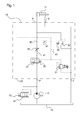
- Fig. 1 shows a circuit diagram of a hydraulic drive unit with a single load 11 and a valve assembly according to the invention 10.
- the consumer 11 in the form of a double-acting cylinder is connected via a first and a second consumer port A; B connected to the valve assembly 10.
- a pump 13 is provided with a constant displacement volume, which hydraulic fluid from a tank 12 can promote to the pump port P of the valve assembly 10.
- a delivery pressure regulator 14 is provided, which is designed in the form of a pressure balance, which is connected in parallel to the pump 13.
- the delivery pressure regulator 14 is pressed by a spring 15 in the closed position, wherein the LS port of the valve assembly 10 with the spring side and the delivery pressure of the pump 13 are connected to the spring opposite side of the delivery pressure regulator 14.
- the delivery pressure regulator 14 opens a connection to the tank 12 when the delivery pressure of the pump 13 exceeds the pressure at the LS connection by the pressure equivalent of the spring 15.
- the valve assembly 10 includes a continuously variable metering orifice 20, which can control the flow of fluid from the pump 13 to the first consumer port A.
- the metering orifice 20 is connected in series with a pressure compensator 22, which is pressed by a spring 23 into the open position. Between the pressure compensator 22 and the metering throttle 20 results in a first pressure 41, which is connected to the spring 23 opposite side of the pressure compensator 22.
- the metering throttle 20 is connected in series with a damping throttle 21, so that a second pressure 42 results between the metering throttle 20 and the damping throttle 21, which pressure is connected to the first consumer port A.
- the second consumer port B is connected to the tank port T, which in turn is connected to the tank 12.
- a first pressure relief valve 31 is connected in series, which in turn is connected to the tank port T. Between the damping throttle 21 and the first pressure relief valve 31 results in a third pressure 43 which is connected to the spring side of the pressure compensator 22.
- the pressure compensator 22 therefore regulates the pressure difference between the first and third pressures 41; 43 to the pressure equivalent of the spring 23 a.
- the trigger pressure of the first pressure relief valve 31 can be adjusted both manually and electrically. The electrical adjustment is provided for connection to the control of a parent machine, such as a tree harvester.
- a second pressure limiting valve 32 which connects the first consumer port A to the tank port T.
- the second pressure limiting valve 32 is pressed by a spring 33 in the closed position, wherein the third pressure 43 is additionally connected to the spring side.
- the pressure at the first consumer port A is connected, so that the second pressure relief valve 32 opens the connection to the tank 12 when the pressure at the first consumer port A exceeds the sum of the third pressure 43 and the pressure equivalent of the spring 33 of the second pressure relief valve 32 ,
- the first pressure relief valve 31 thus causes an energy-saving load pressure control at the first consumer port A, wherein the second pressure relief valve 32 limits the possible pressure peaks on the first consumer port A. It is not necessary to control the second pressure relief valve 32 separately from the outside.
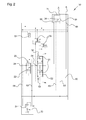
- Fig. 2 1 shows a circuit diagram of a first embodiment of a first consumer assembly 50 according to the invention.
- This consumer assembly 50 is for use in a valve assembly according to the catalog " Mono and disc load-sensing control block - Type M4-12 "from Bosch Rexroth AG (Order No. RD 64276, Edition 08/2010 ) intended.
- the cited catalog is referred to in its entirety and incorporated into the content of the present application.
- the consumer assembly 50 is comprised of first, second and third subassemblies 60; 70; 71 assembled, each of which can be pre-assembled as a whole. Subsequently, the second and third subassemblies 70; 71 is externally attached to the first subassembly 60.
- the first sub-assembly 60 is a valve disc according to the above catalog, compared to the standard state, each with an additional first, second, third and fourth bore 61; 62; 63; 64 was provided.
- the first subassembly 60 is penetrated by a pump line P, a pilot oil feed line X, a pilot oil discharge line Y, an LS line and a tank line T, which are each arranged to be associated Supplement lines from adjacent consumer modules to a line that passes through the entire valve assembly.
- the pump line P is analogous to Fig. 1 connected to a pump, the LS line to the delivery pressure regulator of the pump and the tank line T to the tank.
- the pilot oil feed line X is also connected to the pump or to a separate pilot oil pump with the pilot oil drain line Y connected to the tank.
- the first subassembly 60 includes a proportional directional control valve 52 having a middle blocking position and a first and a second working position.
- the pump line P In the first working position, the pump line P is connected to the first consumer port A via a first continuously variable metering throttle and the second consumer port B is connected to the tank line T.
- the pump line P In the second working position, the pump line P is connected via a second continuously variable metering orifice with the second consumer port B, wherein the first consumer port A is connected to the tank line T.
- the valve spool of the proportional directional control valve 52 is pressed by two return springs 53 in the middle blocking position, wherein the first and the second working position can be adjusted hydraulically with an associated pilot valve 55.
- the pilot valves 55 may be electrically controlled by the controller of the parent machine.
- the already mentioned damping throttle 21 is integrated in the proportional directional control valve 52, so that the third pressure is applied to its LS port 54.
- the LS port 54 of the proportional directional control valve 52 is connected to a shuttle valve 51, the shuttle valves 51 of adjacent first subassemblies 60 being interconnected into a cascade that terminates in the LS port of the valve assembly.
- the LS port 54 of the proportional directional control valve 52 is connected via the second bore 62 to the second subassembly 70, which in turn is connected via the first bore 61 to the control oil discharge line Y.
- a pressure compensator 22 is connected in series, compared to the pressure compensator after Fig. 1 an additional load holding position 24 has.
- the connection is blocked from the pump line P to the proportional directional control valve 52, wherein the pressure compensator 22 is pressed by its spring 23 in the load holding position 24.
- a pressure in the pump line causes the valve spool of the pressure compensator 22 is displaced against the spring 23, so that the connection from the pump line P to the proportional directional control valve 52 is fully open.
- the pressure compensator works after Fig. 2 as the pressure balance according to Fig. 1 ,
- the second subassembly 70 includes the first pressure relief valve 31, the trigger pressure of which is adjustable both electrically and manually.
- the third subassembly 71 comprises the second pressure limiting valve 32.
- the third subassembly 71 is connected to the first and the second consumer connection 65; 66 of the first subassembly 60 grown.
- the first and the second consumer connection 65; 66 are each directly to the first and the second load port A; B of the consumer assembly 50, which are disposed on the third subassembly 71.
- the second pressure relief valve 32 is installed, to which a separate check valve 34 is connected in parallel.
- the return valve 34 is installed so that the consumer can suck hydraulic fluid from the tank, so that no negative pressure can occur in the consumer.
- the spring side 33 of the second pressure limiting valve 32 is connected via the third bore 63 in the first subassembly 60 to the LS port 54 of the proportional directional control valve 52.
- Fig. 3 shows a circuit diagram of a second embodiment of a first consumer assembly according to the invention 50. This differs only in terms of the second pressure relief valve 32 of the first consumer assembly after Fig. 2 , so far as the comments on Fig. 2 can be referenced.
- the check valve 34 has been integrated into the second pressure relief valve 32, so that they can be mounted as a whole Form assembly.
- Such a pressure relief valve is for example from the catalog " Pressure limiting and feed valve, pilot operated - Type MHDBN "from Bosch Rexroth AG (Order No. RD 64602, Edition 09/2011 ), so that in this regard can be made to the statements there.
Landscapes
- Engineering & Computer Science (AREA)
- Physics & Mathematics (AREA)
- Fluid Mechanics (AREA)
- Mechanical Engineering (AREA)
- General Engineering & Computer Science (AREA)
- Fluid-Pressure Circuits (AREA)
- Safety Valves (AREA)
Abstract
Description
- Die Erfindung betrifft eine Ventilbaugruppe gemäß dem Oberbegriff von Anspruch 1.
- Aus dem Katalog "Load-Sensing-Steuerblock in Mono- und Scheibenbauweise - Typ M4-12" der Bosch Rexroth AG (Best-Nr. RD 64276; Ausgabe 08/2010) ist eine Ventilbaugruppe bekannt. Diese Ventilbaugruppe ist aus mehreren als Ganzes montierbaren Verbraucherbaugruppen zusammengesetzt, die aufgrund ihrer geometrischen Form auch als Ventilscheiben bezeichnet werden. Jede Verbraucherbaugruppe weist einen ersten und einen zweiten Verbraucheranschluss zum Anschluss eines zugeordneten hydraulischen Verbrauchers auf, bei dem es sich beispielsweise um einen Zylinder oder einen Hydromotor handeln kann. Die Verbraucherbaugruppe weist einen Pumpenanschluss zum Anschluss einer Pumpe auf, wobei der Pumpenanschluss mit einer Pumpenleitung verbunden ist, welche alle Verbraucherbaugruppen durchsetzt. Weiter ist ein Tankanschluss zum Anschluss eines Tanks vorgesehen, der mit einer Tankleitung verbunden ist, welche ebenfalls alle Verbraucherbaugruppen durchsetzt. Jede Verbraucherbaugruppe weist ein Proportionalwegeventil auf, das zumindest eine stetig verstellbare Zumessdrossel aufweist, welche den Fluidstrom von der Pumpenleitung zu einem der zugeordneten Verbraucheranschlüsse steuern kann. Jeder Zumessdrossel ist eine Druckwaage vorgeschaltet, also pumpenseitig in Reihe geschaltet, so dass sich zwischen der Druckwaage und der Zumessdrossel ein erster Druck ergibt.
- Weiter ist jeder Verbraucherbaugruppe ein Wechselventil zugeordnet, an das ein Lastdruck der zugeordneten Verbraucherbaugruppe angeschlossen ist. Die Wechselventile sind in einer Kaskade zusammengeschaltet, die am LS-Anschluss endet, so dass dort der höchste Lastdruck aller Verbraucherbaugruppen anliegt. Der LS-Anschluss ist wiederum mit einem Pumpenregler verbunden, der den Pumpenförderdruck auf einen Druck einregelt, der um eine vorgegebene dritte Druckdifferenz über dem höchsten Lastdruck liegt. Bei der Pumpe kann es sich im einfachsten Fall um eine Pumpe mit konstantem Verdrängungsvolumen handeln, wobei der Druckregler eine parallel geschaltete Druckwaage ist, welche einen Teil des Pumpenförderstroms zurück in den Tank leitet. Es kann aber auch eine Pumpe mit verstellbarem Verdrängungsvolumen vorgesehen sein, wobei der Pumpenregler das Verdrängungsvolumen so einstellt, dass sich der gewünschte Förderdruck ergibt. Die letztgenannte Ausführungsform ist deutlich energiesparender.
- Um nun den bereits angesprochenen Lastdruck auf einen maximalen Wert begrenzen zu können sind erste Druckbegrenzungsventile bekannt, die auch als LS-Druckbegrenzungsventile bezeichnet werden. Wenn der Lastdruck über den Auslösedruck des ersten Druckbegrenzungsventils steigt, leiten diese so viel Hydraulikfluid in den Tank ab, bis der Lastdruck unter den Auslösedruck abfällt. Dabei soll möglichst wenig Hydraulikfluid in den Tank abgeleitet werden, weil dies mit hohen Energieverlusten verbunden ist. Deshalb ist eine Dämpfungsdrossel vorgesehen, welche der Zumessdrossel tankseitig in Reihe geschaltet ist, wobei der Dämpfungsdrossel das erste Druckbegrenzungsventil tankseitig in Reihe geschaltet ist. Zwischen der Zumessdrossel und der Dämpfungsdrossel ergibt sich ein zweiter Druck, der mit dem der Zumessdrossel zugeordneten Verbraucheranschluss verbunden ist. Zwischen der Dämpfungsdrossel und dem ersten Druckbegrenzungsventil ergibt sich ein dritter Druck, wobei der erste und der dritte Druck so an der Druckwaage angeschlossen sind, dass diese eine erste vorgegebene Druckdifferenz zwischen dem ersten und dem dritten Druck einregelt. Der dritte Druck ist der bereits angesprochene Lastdruck, der mit dem Wechselventil verbunden ist.
- Eine derartige Ventilbaugruppe kann beispielsweise in einer Baumerntemaschine eingesetzt werden. Der Verbraucher ist dabei ein Zylinder, der die Entastungsmesser gegen einen Baumstamm drückt, um die Äste an einem Baumstamm zu entfernen. Die an dem ersten Druckbegrenzungsventil eingestellte Auslösekraft entspricht dabei der Kraft, mit der die genannten Entastungsmesser im Mittel gegen den Baumstamm gedrückt werden. Diese Kraft muss an die Härte des vorliegenden Holzes angepasst werden, damit der Baustamm nicht beschädigt wird. Die Auslösekraft des ersten Druckbegrenzungsventils ist deshalb elektrisch verstellbar, damit sie durch den Benutzer an der Steuerung der Baumerntemaschine eingestellt werden kann.
- Wird nun ein Baumstamm durch die Baumerntemaschine bewegt, so werden die Entastungsmesser an den Astansätzen ruckartig beschleunigt, weil sie diesen ausweichen müssen. Dies bewirkt Druckspitzen beim zweiten Druck, der maßgeblich für die Anpresskraft ist. Dies liegt daran, dass der zweite Druck wie oben erläutert, zwecks Energieeinsparung nur über die Dämpfungsdrossel mit dem ersten Druckbegrenzungsventil verbunden ist. Die genannten Druck- bzw. Kraftspitzen haben zur Folge, dass der Baumstamm beim Entasten beschädigt wird.
- Die Aufgabe der Erfindung besteht darin, die angesprochenen Druckspitzen des zweiten Drucks zu vermindern. Insbesondere soll beim Einsatz der Ventilbaugruppe in einer Baumerntemaschine eine Beschädigung des Baumstammes vermieden werden. Dabei soll übermäßiger Energieverlust vermieden werden.
- Gemäß dem selbständigen Anspruch wird diese Aufgabe dadurch gelöst, dass der zweite Druck an ein zweites Druckbegrenzungsventil angeschlossen ist, dessen Auslösedruck verstellbar ist. Durch das zweite Druckbegrenzungsventil wird der zweite Druck nach oben begrenzt, so dass die Druckspitzen des zweiten Drucks nach oben begrenzt werden. Beim Auslösen des zweiten Druckbegrenzungsventils fließt ein großer Fluidstrom in den Tank ab, so dass große Energieverluste auftreten. Der Auslösedruck muss daher so eingestellt werden, dass das zweite Druckbegrenzungsventil möglichst selten anspricht, wobei jedoch alle schädlichen Druckspitzen vermieden werden. Deshalb ist der Auslösedruck des zweiten Druckbegrenzungsventils verstellbar. Dabei kann daran gedacht sein, dass der Auslösedruck des zweiten Druckbegrenzungsventils elektrisch verstellbar ist, so dass er von der Steuerung der Baumerntemaschine auf den gewünschten Wert eingestellt werden kann.
- In den abhängigen Ansprüchen sind vorteilhafte Weiterbildungen und Verbesserungen der Erfindung angegeben.
- Der Auslösedruck des zweiten Druckbegrenzungsventils kann mittels des dritten Drucks hydraulisch so verstellbar sein, dass er um eine vorgegebene zweite Druckdifferenz über dem dritten Druck liegt. Die bereits angesprochene elektrische Ansteuerung hat den Nachteil, dass sie sehr aufwändig ist, insbesondere wenn die Auslösekraft mit hoher Genauigkeit eingestellt werden soll. Das vorgeschlagene zweite Druckbegrenzungsventil ist dagegen sehr einfach aufgebaut und wird überdies bereits serienmäßig hergestellt. Darüber hinaus erfordert die vorgeschlagene Lösung wesentlich weniger Bauraum, als die genannte elektrische Ansteuerung des Auslösedrucks. Weiter ist die vorgeschlagene hydraulische Ansteuerung des Auslösedrucks deutlich zuverlässiger als eine elektrische Ansteuerung. Zuletzt muss der Benutzer der Baumerntemaschine nur einen einzigen Parameter einstellen, nämlich die Anpresskraft bzw. den Auslösedruck des ersten Druckbegrenzungsventils.
- Die Druckwaage kann eine Lasthaltestellung aufweisen, in der sie gesperrt ist, wobei sich die Lasthaltestellung dann einstellt, wenn der Druck am Pumpenanschluss unter den zweiten Druck fällt. Hierdurch soll erreicht werden, dass der Verbraucher still steht, wenn der Pumpendruck nicht mehr ausreicht, um diesen zu bewegen. Dadurch wird die Sicherheit des gesamten Systems erhöht. Gerade diese Maßnahme verstärkt aber die bereits genannten Druckspitzen des zweiten Drucks, so dass die Erfindung bei dieser Ausgestaltung der Ventilbaugruppe besonders vorteilhaft ist.
- Dem zweiten Druckbegrenzungsventil kann ein Rückschlagventil parallel geschaltet sein, das so eingebaut ist, dass der zweite Druck nicht unter den Umgebungsdruck abfallen kann. Über das Rückschlagventil kann der Verbraucher Hydraulikfluid aus dem Tank ansaugen. Damit ist ausgeschlossen, dass in den Druckräumen des Verbrauchers ein Freiraum entsteht, der nicht mit Hydraulikfluid gefüllt ist. Ein solcher Freiraum könnte unkontrollierte Bewegungen des Verbrauchers zur Folge haben, die sehr gefährlich sind.
- Das Rückschlagventil und das zweite Druckbegrenzungsventil können in Form einer als Ganzes montierbaren Baugruppe ausgebildet sein. Damit ergibt sich eine besonders kompakte Ventilbaugruppe, die überdies leicht montierbar ist. Die genannte Baugruppe lässt sich überdies serienmäßig und damit kostengünstig herstellen, da sie auch für viele andere Anwendungen einsetzbar ist.
- Der Auslösedruck des ersten Druckbegrenzungsventils kann sowohl manuell als auch elektrisch verstellbar sein. Über die elektrische Verstellung kann der Auslösedruck des ersten Druckbegrenzungsventils von der Steuerung einer übergeordneten Maschine eingestellt werden. Mittels der manuellen Verstellung kann sichergestellt werden, dass der Auslösedruck einen vorgegebenen Wert sicher nicht unterschreitet. Hierdurch wird die Betriebssicherheit der übergeordneten Maschine gesteigert.
- Die Zumessdrossel kann Bestandteil eines Proportionalwegeventils sein, mit dem die Bewegungsrichtung des zugeordneten Verbrauchers verstellt werden kann. Das Proportionalwegeventil besitzt hierfür wenigstens zwei stetig verstellbare Zumessdrosseln, wobei eine Drossel mit dem ersten Verbraucheranschluss und die zweite Drossel mit dem zweiten Verbraucheranschluss verbunden ist. Die Drosselquerschnitte der beiden Zumessdrosseln können von einem gemeinsamen Ventilschieber eingestellt werden, so dass sich die gewünschte Einstellbarkeit der Bewegungsrichtung ergibt.
- Der erste und der zweite Verbraucheranschluss kann an einer ersten als Ganzes montierbaren ersten Verbraucherbaugruppe vorgesehen sein, wobei wenigstens eine weitere als Ganzes montierbare Verbraucherbaugruppe vorgesehen ist, an die ein zugeordneter Verbraucher angeschlossen werden kann, wobei eine Pumpenleitung mit dem Pumpenanschluss und eine Tankleitung mit dem Tankanschluss verbunden sind, wobei die Pumpen- und die Tankleitung jeweils alle Verbraucherbaugruppen durchsetzen, wobei jede Verbraucherbaugruppe ein Wechselventil aufweist, welche in einer Kaskade zusammengeschaltet sind, die am LS-Anschluss endet, wobei der dritte Druck an das Wechselventil der ersten Verbraucherbraugruppe angeschlossen ist. Wie bereits eingangs angesprochen ist die vorliegende Erfindung in erster Linie für eine Ventilbaugruppe gedacht, an der mehrere Verbraucher angeschlossen sind, die über eine gemeinsame Pumpe mit Hydraulikfluid versorgt werden.
- Das erste und/oder das zweite Druckbegrenzungsventil können als Ganzes montierbare Baugruppen ausgebildet sein, die von außen an die erste Verbraucherbaugruppe angebaut sind. Hierdurch soll erreicht werden, dass die vorliegende Erfindung mit der bereits serienmäßig hergestellten Ventilbaugruppe verwendet werden kann. Die vorhandenen Verbraucherbaugruppen müssen dabei nur mit weinigen zusätzlichen Bohrungen versehen werden.
- Die Erfindung wird im Folgenden anhand der beigefügten Zeichnungen näher erläutert. Es stellt dar:
- Fig. 1
- einen Schaltplan einer hydraulischen Antriebeseinheit mit einem einzigen Verbraucher und einer erfindungsgemäßen Ventilbaugruppe;
- Fig. 2
- einen Schaltplan einer ersten Ausführungsform einer erfindungsgemäßen ersten Verbraucherbaugruppe; und
- Fig. 3
- einen Schaltplan einer zweiten Ausführungsform einer erfindungsgemäßen ersten Verbraucherbaugruppe.
-
Fig. 1 zeigt einen Schaltplan einer hydraulischen Antriebseinheit mit einem einzigen Verbraucher 11 und einer erfindungsgemäßen Ventilbaugruppe 10. Der Verbraucher 11 in Form eines doppeltwirkenden Zylinders ist über einen ersten und einen zweiten Verbraucheranschluss A; B mit der Ventilbaugruppe 10 verbunden. Weiter ist eine Pumpe 13 mit konstantem Verdrängungsvolumen vorgesehen, welche Hydraulikfluid aus einem Tank 12 zu dem Pumpenanschluss P der Ventilbaugruppe 10 fördern kann. Außerdem ist ein Förderdruckregler 14 vorgesehen, der in Form einer Druckwaage ausgeführt ist, welche zur Pumpe 13 parallel geschaltet ist. Der Förderdruckregler 14 wird von einer Feder 15 in die geschlossene Stellung gedrückt, wobei der LS-Anschluss der Ventilbaugruppe 10 mit der Federseite und der Förderdruck der Pumpe 13 mit der Federgegenseite des Förderdruckreglers 14 verbunden sind. Der Förderdruckregler 14 öffnet eine Verbindung zum Tank 12, wenn der Förderdruck der Pumpe 13 den Druck am LS-Anschluss um das Druckäquivalent der Feder 15 übersteigt. - Anstelle der vorliegenden Pumpe 13 mit konstantem Verdrängungsvolumen kann auch eine Pumpe mit verstellbarem Verdrängungsvolumen vorgesehen sein, wobei der Förderdruckregler das Verdrängungsvolumen der Pumpe verstellt. Diese Ausführungsform ist energiesparender.
- Die Ventilbaugruppe 10 umfasst eine stetig verstellbare Zumessdrossel 20, welche den Fluidstrom von der Pumpe 13 zum ersten Verbraucheranschluss A steuern kann. Pumpenseitig ist der Zumessdrossel 20 eine Druckwaage 22 in Reihe geschaltet, welche von einer Feder 23 in die geöffnete Stellung gedrückt wird. Zwischen der Druckwaage 22 und der Zumessdrossel 20 ergibt sich ein erster Druck 41, der mit der der Feder 23 gegenüberliegenden Seite der Druckwaage 22 verbunden ist. Tankseitig ist der Zumessdrossel 20 eine Dämpfungsdrossel 21 in Reihe geschaltet, so dass sich zwischen der Zumessdrossel 20 und der Dämpfungsdrossel 21 ein zweiter Druck 42 ergibt, der mit dem ersten Verbraucheranschluss A verbunden ist. Der zweite Verbraucheranschluss B ist mit dem Tankanschluss T verbunden, der wiederum mit dem Tank 12 verbunden ist.
- Tankseitig ist der Dämpfungsdrossel 21 ein erstes Druckbegrenzungsventil 31 in Reihe geschaltet, das wiederum mit dem Tankanschluss T verbunden ist. Zwischen der Dämpfungsdrossel 21 und dem ersten Druckbegrenzungsventil 31 ergibt sich ein dritter Druck 43, der mit der Federseite der Druckwaage 22 verbunden ist. Die Druckwaage 22 regelt daher die Druckdifferenz zwischen dem ersten und dem dritten Druck 41; 43 auf das Druckäquivalent der Feder 23 ein. Der Auslösedruck des ersten Druckbegrenzungsventils 31 kann sowohl manuell als auch elektrisch verstellt werden. Die elektrische Verstellung ist zum Anschluss an die Steuerung einer übergeordneten Maschine, beispielsweise einer Baumerntemaschine vorgesehen.
- Weiter ist ein zweites Druckbegrenzungsventil 32 vorgesehen, welches den ersten Verbraucheranschluss A mit dem Tankanschluss T verbindet. Das zweite Druckbegrenzungsventil 32 wird von einer Feder 33 in die geschlossene Stellung gedrückt, wobei an der Federseite zusätzlich der dritte Druck 43 angeschlossen ist. An der Federgegenseite ist der Druck am ersten Verbraucheranschluss A angeschlossen, so dass das zweite Druckbegrenzungsventil 32 die Verbindung zum Tank 12 öffnet, wenn der Druck am ersten Verbraucheranschluss A die Summe aus dem dritten Druck 43 und dem Druckäquivalent der Feder 33 des zweiten Druckbegrenzungsventils 32 übersteigt. Der Auslösedruck des zweiten Druckbegrenzungsventils ist also immer um das genannte Druckäquivalent höher als der Auslösedruck des ersten Druckbegrenzungsventils 31. Das erste Druckbegrenzungsventil 31 bewirkt damit eine energiesparende Lastdruckregelung am ersten Verbraucheranschluss A, wobei das zweite Druckbegrenzungsventil 32 die dabei möglichen Druckspitzen am ersten Verbraucheranschluss A begrenzt. Dabei ist es nicht erforderlich, das zweite Druckbegrenzungsventil 32 gesondert von außen anzusteuern.
-
Fig. 2 zeigt einen Schaltplan einer ersten Ausführungsform einer erfindungsgemäßen ersten Verbraucherbaugruppe 50. Diese Verbraucherbaugruppe 50 ist zur Verwendung in einer Ventilbaugruppe gemäß dem Katalog "Load-Sensing-Steuerblock in Mono-und Scheibenbauweise - Typ M4-12" der Bosch Rexroth AG (Best-Nr. RD 64276; Ausgabe 08/2010) vorgesehen. Der genannte Katalog wird mit seinem gesamten Inhalt in Bezug genommen und zum Inhalt der vorliegenden Anmeldung gemacht. - Die Verbraucherbaugruppe 50 ist aus einer ersten, einer zweiten und einer dritten Unterbaugruppe 60; 70; 71 zusammengesetzt, die jeweils als Ganzes vormontiert werden können. Anschließend werden die zweite und die dritte Unterbaugruppe 70; 71 von außen an die erste Unterbaugruppe 60 angebaut. Die erste Unterbaugruppe 60 ist eine Ventilscheibe gemäß dem obigen Katalog, die gegenüber dem Serienzustand mit je einer zusätzlichen ersten, zweiten, dritten und vierten Bohrung 61; 62; 63; 64 versehen wurde. Die erste Unterbaugruppe 60 wird von einer Pumpenleitung P, einer Steuerölzuführleitung X, einer Steuerölabführleitung Y, einer LS-Leitung und einer Tankleitung T durchsetzt, die jeweils so angeordnet sind, dass sich zugeordnete Leitungen von benachbarten Verbraucherbaugruppen zu einer Leitung ergänzen, welche die gesamte Ventilbaugruppe durchsetzt. Die Pumpenleitung P wird dabei analog zur
Fig. 1 an eine Pumpe angeschlossen, die LS-Leitung an den Förderdruckregler der Pumpe und die Tankleitung T an den Tank. Die Steuerölzuführleitung X wird ebenfalls an die Pumpe oder an eine gesonderte Steuerölpumpe angeschlossen, wobei die Steuerölabführleitung Y an den Tank angeschlossen wird. - Die erste Unterbaugruppe 60 umfasst ein Proportionalwegeventil 52 mit einer mittleren Sperrstellung und einer ersten und einer zweiten Arbeitsstellung. In der ersten Arbeitsstellung ist die Pumpenleitung P über eine erste stetig verstellbare Zumessdrossel mit dem ersten Verbraucheranschluss A und der zweite Verbraucheranschluss B mit der Tankleitung T verbunden. In der zweiten Arbeitsstellung ist die Pumpenleitung P über eine zweite stetig verstellbare Zumessdrossel mit dem zweiten Verbraucheranschluss B verbunden, wobei der erste Verbraucheranschluss A mit der Tankleitung T verbunden ist. In der Sperrstellung sind alle genannten Verbindungen gesperrt. Der Ventilschieber des Proportionalwegeventils 52 wird von zwei Rückstellfedern 53 in die mittlere Sperrstellung gedrückt, wobei die erste und die zweite Arbeitsstellung mit einem zugeordneten Vorsteuerventil 55 hydraulisch eingestellt werden können. Die Vorsteuerventile 55 können von der Steuerung der übergeordneten Maschine elektrisch angesteuert werden.
- Weiter ist in dem Proportionalwegeventil 52 die bereits angesprochene Dämpfungsdrossel 21 integriert, so dass an dessen LS-Anschluss 54 der dritte Druck anliegt. Der LS-Anschluss 54 des Proportionalwegeventils 52 ist mit einem Wechselventil 51 verbunden, wobei die Wechselventile 51 benachbarter erster Unterbaugruppen 60 zu einer Kaskade zusammengeschaltet sind, welche im LS-Anschluss der Ventilbaugruppe endet. Der LS-Anschluss 54 des Proportionalwegeventils 52 ist über die zweite Bohrung 62 mit der zweiten Unterbaugruppe 70 verbunden, welche wiederum über die erste Bohrung 61 mit der Steuerölabführleitung Y verbunden ist.
- Pumpenseitig ist dem Proportionalwegeventil 52 eine Druckwaage 22 in Reihe geschaltet, die gegenüber der Druckwaage nach
Fig. 1 eine zusätzliche Lasthaltestellung 24 aufweist. In der Lasthaltestellung 24 ist die Verbindung von der Pumpenleitung P zum Proportionalwegeventil 52 gesperrt, wobei die Druckwaage 22 von ihrer Feder 23 in die Lasthaltestellung 24 gedrückt wird. Ein Druck in der Pumpenleitung bewirkt jedoch, dass der Ventilschieber der Druckwaage 22 gegen die Feder 23 verschoben wird, so dass die Verbindung von der Pumpenleitung P zum Proportionalwegeventil 52 ganz geöffnet ist. Im Übrigen arbeitet die Druckwaage nachFig. 2 wie die Druckwaage gemäß derFig. 1 . - Die zweite Unterbaugruppe 70 umfasst das erste Druckbegrenzungsventil 31, dessen Auslösedruck sowohl elektrisch als auch manuell einstellbar ist. Die dritte Unterbaugruppe 71 umfasst das zweite Druckbegrenzungsventil 32. Dabei ist die dritte Unterbaugruppe 71 an den ersten und den zweiten Verbraucheranschluss 65; 66 der ersten Unterbaugruppe 60 angebaut. Der erste und der zweite Verbraucheranschluss 65; 66 sind jeweils direkt mit dem ersten und dem zweiten Verbraucheranschluss A; B der Verbraucherbaugruppe 50 verbunden, welche an der dritten Unterbaugruppe 71 angeordnet sind. Zwischen dem ersten Verbraucheranschluss A und der vierten Bohrung 64 in der ersten Unterbaugruppe 60, welche zur Tankleitung führt, ist das zweite Druckbegrenzungsventil 32 eingebaut, dem ein gesondertes Rückschlagventil 34 parallel geschaltet ist. Das Rückschalventil 34 ist dabei so eingebaut, dass der Verbraucher Hydraulikfluid aus dem Tank ansaugen kann, so dass kein Unterdruck im Verbraucher entstehen kann. Die Federseite 33 des zweiten Druckbegrenzungsventils 32 ist über die dritte Bohrung 63 in der ersten Unterbaugruppe 60 mit dem LS-Anschluss 54 des Proportionalwegeventils 52 verbunden.
-
Fig. 3 zeigt einen Schaltplan einer zweiten Ausführungsform einer erfindungsgemäßen ersten Verbraucherbaugruppe 50. Diese unterscheidet sich nur hinsichtlich des zweiten Druckbegrenzungsventils 32 von der ersten Verbraucherbaugruppe nachFig. 2 , so dass insoweit auf die Ausführungen zuFig. 2 verwiesen werden kann. Bei der zweiten Verbraucherbaugruppe wurde das Rückschlagventil 34 in das zweite Druckbegrenzungsventil 32 integriert, so dass diese eine als Ganzes montierbare Baugruppe bilden. Ein derartiges Druckbegrenzungsventil ist beispielsweise aus dem Katalog "Druckbegrenzungs- und Einspeiseventil, vorgesteuert - Typ MHDBN" der Bosch Rexroth AG (Best. Nr. RD 64602; Ausgabe 09/2011) bekannt, so dass insoweit auf die dortigen Ausführungen verwiesen werden kann. -
- A
- erster Verbraucheranschluss
- B
- zweiter Verbraucheranschluss
- P
- Pumpenanschluss bzw. Pumpenleitung
- T
- Tankanschluss bzw. Tankleitung
- LS
- LS-Anschluss bzw. LS-Leitung der Ventilbaugruppe
- X
- Steuerölzuführleitung
- Y
- Steuerölabführleitung
- 10
- Ventilbaugruppe
- 11
- Verbraucher
- 12
- Tank
- 13
- Pumpe
- 14
- Förderdruckregler
- 15
- Feder des Förderdruckreglers
- 20
- Zumessdrossel
- 21
- Dämpfungsdrossel
- 22
- Druckwaage
- 23
- Feder der Druckwaage
- 24
- Lasthaltestellung
- 31
- erstes Druckbegrenzungsventil
- 32
- zweites Druckbegrenzungsventil
- 33
- Feder des zweiten Druckbegrenzungsventils
- 34
- Rückschlagventil
- 41
- erster Druck
- 42
- zweiter Druck
- 43
- dritter Druck
- 50
- erste Verbraucherbaugruppe
- 51
- Wechselventil
- 52
- Proportionalwegeventil
- 53
- Rückstellfeder des Proportionalwegeventils
- 54
- LS-Anschluss des Proportionalwegeventils
- 55
- Vorsteuerventil
- 60
- erste Unterbaugruppe
- 61
- erste Bohrung
- 62
- zweite Bohrung
- 63
- dritte Bohrung
- 64
- erster Verbraucheranschluss der ersten Unterbaugruppe
- 65
- zweiter Verbraucheranschluss der ersten Unterbaugruppe
- 70
- zweite Unterbaugruppe
- 71
- dritte Unterbaugruppe
Claims (9)
- Ventilbaugruppe (10) mit einem ersten und einem zweiten Verbraucheranschluss (A; B) zum Anschluss eines hydraulischen Verbrauchers (11), einem Pumpenanschluss (P) zum Anschluss einer Pumpe (13), einem Tankanschluss (T) zum Anschluss eines Tanks (12) und einem LS-Anschluss (LS) zum Anschluss an einen Förderdruckregler (14) der Pumpe (13),
wobei eine stetig verstellbare Zumessdrossel (20) vorgesehen ist, der eine Druckwaage (22) pumpenseitig in Reihe geschaltet ist, welche mit dem Pumpenanschluss (P) verbunden ist, so dass sich zwischen der Zumessdrossel (20) und der Druckwaage (22) ein erster Druck (41) ergibt, wobei der Zumessdrossel (20) eine Dämpfungsdrossel (21) tankseitig in Reihe geschaltet ist, so dass sich zwischen der Zumessdrossel (20) und der Dämpfungsdrossel (21) ein zweiter Druck (42) ergibt, der mit einem der Verbraucheranschlüsse (A; B) verbunden ist, wobei der Dämpfungsdrossel (21) ein erstes Druckbegrenzungsventil (31) mit verstellbarem Auslösedruck tankseitig in Reihe geschaltet ist, so dass sich zwischen der Dämpfungsdrossel (21) und dem ersten Druckbegrenzungsventil (31) ein dritter Druck (43) ergibt, der wenigstens mittelbar mit dem LS-Anschluss (LS) verbunden ist, wobei der erste und der dritte Druck (41; 43) so an die Druckwaage (22) angeschlossen sind, dass die Druckwaage (22) eine erste vorgegebene Druckdifferenz zwischen dem ersten und dem dritten Druck (41; 43) einregelt,
dadurch gekennzeichnet, dass der zweite Druck (42) an ein zweites Druckbegrenzungsventil (32) angeschlossen ist, dessen Auslösedruck verstellbar ist. - Ventilbaugruppe nach Anspruch 1,
dadurch gekennzeichnet, dass der Auslösedruck des zweiten Druckbegrenzungsventils (32) mittels des dritten Drucks (43) hydraulisch so verstellbar ist, dass er um eine vorgegebene zweite Druckdifferenz über dem dritten Druck (43) liegt. - Ventilbaugruppe nach einem der vorstehenden Ansprüche,
dadurch gekennzeichnet, dass die Druckwaage (22) eine Lasthaltestellung (24) aufweist, in der sie gesperrt ist, wobei sich die Lasthaltestellung (24) dann einstellt, wenn der Druck am Pumpenanschluss (P) unter den zweiten Druck (42) fällt. - Ventilbaugruppe nach einem der vorstehenden Ansprüche,
dadurch gekennzeichnet, dass dem zweiten Druckbegrenzungsventil (32) ein Rückschlagventil (34) parallel geschaltet ist, das so eingebaut ist, dass der zweite Druck (42) nicht unter den Umgebungsdruck abfallen kann. - Ventilbaugruppe nach Anspruch 4,
dadurch gekennzeichnet, dass das Rückschlagventil (34) und das zweite Druckbegrenzungsventil (32) in Form einer als Ganzes montierbaren Baugruppe ausgebildet sind. - Ventilbaugruppe nach einem der vorstehenden Ansprüche,
dadurch gekennzeichnet, dass der Auslösedruck des ersten Druckbegrenzungsventils (31) sowohl manuell als auch elektrisch verstellbar ist. - Ventilbaugruppe nach einem der vorstehenden Ansprüche,
dadurch gekennzeichnet, dass die Zumessdrossel (20) Bestandteil eines Proportionalwegeventils (52) ist, mit dem die Bewegungsrichtung des zugeordneten Verbrauchers (11) verstellt werden kann. - Ventilbaugruppe, nach einem der vorstehenden Ansprüche,
dadurch gekennzeichnet, dass der erste und der zweite Verbraucheranschluss (A; B) an einer ersten als Ganzes montierbaren ersten Verbraucherbaugruppe (50) vorgesehen sind, wobei wenigstens eine weitere als Ganzes montierbare Verbraucherbaugruppe vorgesehen ist, an die ein zugeordneter Verbraucher angeschlossen werden kann, wobei eine Pumpenleitung (P) mit dem Pumpenanschluss und eine Tankleitung (T) mit dem Tankanschluss verbunden sind, wobei die Pumpen- und die Tankleitung (P; T) jeweils alle Verbraucherbaugruppen durchsetzen, wobei jede Verbraucherbaugruppe ein Wechselventil (51) aufweist, welche in einer Kaskade zusammengeschaltet sind, die am LS-Anschluss (LS) endet, wobei der dritte Druck (43) an das Wechselventil (51) der ersten Verbraucherbraugruppe (50) angeschlossen ist. - Ventilbaugruppe nach Anspruch 8,
dadurch gekennzeichnet, dass das erste und/oder das zweite Druckbegrenzungsventil (31; 32) als als Ganzes montierbare Baugruppen (70; 71) ausgebildet sind, die von außen an die erste Verbraucherbaugruppe (60) angebaut sind.
Applications Claiming Priority (1)
| Application Number | Priority Date | Filing Date | Title |
|---|---|---|---|
| DE102012001549A DE102012001549A1 (de) | 2012-01-26 | 2012-01-26 | Load-Sensing-Ventilbaugruppe mit Drucksteuerung |
Publications (3)
| Publication Number | Publication Date |
|---|---|
| EP2620656A2 true EP2620656A2 (de) | 2013-07-31 |
| EP2620656A3 EP2620656A3 (de) | 2017-03-29 |
| EP2620656B1 EP2620656B1 (de) | 2018-12-26 |
Family
ID=47561339
Family Applications (1)
| Application Number | Title | Priority Date | Filing Date |
|---|---|---|---|
| EP13150235.3A Not-in-force EP2620656B1 (de) | 2012-01-26 | 2013-01-04 | Load-Sensing-Ventilbaugruppe mit Drucksteuerung |
Country Status (3)
| Country | Link |
|---|---|
| EP (1) | EP2620656B1 (de) |
| BR (1) | BR102013001832A2 (de) |
| DE (1) | DE102012001549A1 (de) |
Cited By (2)
| Publication number | Priority date | Publication date | Assignee | Title |
|---|---|---|---|---|
| CN105443475A (zh) * | 2015-12-30 | 2016-03-30 | 中国铁建重工集团有限公司 | 负载压力自适应控制液压系统、控制方法及预切槽机 |
| FR3054008A1 (fr) * | 2016-07-13 | 2018-01-19 | Bosch Gmbh Robert | Installation de distributeur hydraulique equipee d'un absorbeur de chocs de pression |
Families Citing this family (1)
| Publication number | Priority date | Publication date | Assignee | Title |
|---|---|---|---|---|
| DE102020210441A1 (de) * | 2020-08-17 | 2022-02-17 | Hawe Hydraulik Se | Proportional-Schieberventil mit einem Druckbegrenzungsventil, Druckbegrenzungsventil und Hydrauliksystem |
Family Cites Families (5)
| Publication number | Priority date | Publication date | Assignee | Title |
|---|---|---|---|---|
| DE3709504C2 (de) * | 1987-03-23 | 1995-02-02 | Rexroth Mannesmann Gmbh | Ventileinrichtung |
| DE4420682A1 (de) * | 1994-06-14 | 1996-01-04 | Rexroth Mannesmann Gmbh | Hydrauliksteuerung für eine teilende Werkzeugmaschine |
| DE19715020A1 (de) * | 1997-04-11 | 1998-10-15 | Rexroth Mannesmann Gmbh | Hydraulische Steueranordnung, insbesondere für ein Fahrzeug zum Transport von Absetzmulden |
| DE19734020A1 (de) * | 1997-08-06 | 1999-02-11 | Mannesmann Rexroth Ag | Vorgesteuertes Druckbegrenzungsventil |
| FI104531B (fi) * | 1998-09-15 | 2000-02-29 | Timberjack Oy | Karsintalaitteisto ja menetelmä karsintalaitteistossa |
-
2012
- 2012-01-26 DE DE102012001549A patent/DE102012001549A1/de not_active Withdrawn
-
2013
- 2013-01-04 EP EP13150235.3A patent/EP2620656B1/de not_active Not-in-force
- 2013-01-24 BR BR102013001832A patent/BR102013001832A2/pt not_active Application Discontinuation
Non-Patent Citations (3)
| Title |
|---|
| "Druckbegrenzungs- und Einspeiseventil, vorgesteuert - Typ MHDBN", September 2011, BOSCH REXROTH AG |
| "Load-Sensing-Steuerblock in Mono- und Scheibenbauweise - Typ M4-12", August 2010, BOSCH REXROTH AG |
| "Load-Sensing-Steuerblock in Mono-und Scheibenbauweise - Typ M4-12", August 2010, BOSCH REXROTH AG |
Cited By (3)
| Publication number | Priority date | Publication date | Assignee | Title |
|---|---|---|---|---|
| CN105443475A (zh) * | 2015-12-30 | 2016-03-30 | 中国铁建重工集团有限公司 | 负载压力自适应控制液压系统、控制方法及预切槽机 |
| CN105443475B (zh) * | 2015-12-30 | 2017-10-27 | 中国铁建重工集团有限公司 | 负载压力自适应控制液压系统、控制方法及预切槽机 |
| FR3054008A1 (fr) * | 2016-07-13 | 2018-01-19 | Bosch Gmbh Robert | Installation de distributeur hydraulique equipee d'un absorbeur de chocs de pression |
Also Published As
| Publication number | Publication date |
|---|---|
| EP2620656B1 (de) | 2018-12-26 |
| DE102012001549A1 (de) | 2013-08-01 |
| BR102013001832A2 (pt) | 2016-02-23 |
| EP2620656A3 (de) | 2017-03-29 |
Similar Documents
| Publication | Publication Date | Title |
|---|---|---|
| EP1915538B1 (de) | Schaltung zur ansteuerung eines doppeltwirkenden hydraulischen antriebszylinders | |
| DE102013220750A1 (de) | Ventilblock mit einer Ventilanordnung | |
| DE102017219942A1 (de) | Ventilanordung für Hubwerkssteuerung mit einer Druckregelvorrichtung | |
| EP0141301B1 (de) | Hydraulischer Kreislauf für einen eine Last bewegenden Motor | |
| EP3012463B1 (de) | Hydraulikaggregat | |
| EP2672125B1 (de) | Hydrauliksystem zur sicheren Druckversorgung mindestens eines Verbrauchers | |
| DE102012208938A1 (de) | Closed-Center-Steuereinrichtung mit Konstant- und Verstellpumpe | |
| EP3625457B1 (de) | Steuervorrichtung zum versorgen mindestens eines hydraulischen verbrauchers mit fluid | |
| EP2620656B1 (de) | Load-Sensing-Ventilbaugruppe mit Drucksteuerung | |
| DE102007055377A1 (de) | Hydraulische Steueranordnung und Wegeventilsektion | |
| EP3398418A1 (de) | Hydrauliksystem einer land- oder bauwirtschaftlich nutzbaren arbeitsmaschine | |
| DE2952369C2 (de) | Hydraulische Vorrangschaltung, insbesondere für Hydraulikanlagen in Fahrzeugen | |
| DE102006008940A1 (de) | Hydraulische Steueranordnung | |
| EP3135924B1 (de) | Hydrauliksteuerung | |
| EP2891805A2 (de) | Steueranordnung und Steuerventil für eine derartige Steueranordnung | |
| DE19603899A1 (de) | Hydraulische Steuervorrichtung zur Druckmittelversorgung mehrerer hydraulischer Verbraucher | |
| WO2003087585A1 (de) | Hydraulische steueranordnung in load-sensing technik | |
| DE102011079691B3 (de) | Steuerkolbenzentrierung für hydrostatische servoverstelleinrichtungen von hydraulikmaschinen | |
| EP1711715A1 (de) | Messblendenanordnung für ein hydraulisches stromteil- und stromsummiergerät | |
| DE3844405C2 (de) | Ventilanordnung für ein hydraulisches System | |
| DE10119276B4 (de) | Hydraulischer Steuerkreis | |
| EP1954949B1 (de) | Hydraulische steuervorrichtung | |
| DE102016215747A1 (de) | Ventilanordnung für eine erste und eine zweite Pumpe | |
| DE4026849C2 (de) | Ventilanordnung zum Erzeugen eines Steuerdrucks in einer hydraulischen Anlage | |
| DE102023205767B3 (de) | Hydraulikventilverband und Mobilhydraulik |
Legal Events
| Date | Code | Title | Description |
|---|---|---|---|
| PUAI | Public reference made under article 153(3) epc to a published international application that has entered the european phase |
Free format text: ORIGINAL CODE: 0009012 |
|
| AK | Designated contracting states |
Kind code of ref document: A2 Designated state(s): AL AT BE BG CH CY CZ DE DK EE ES FI FR GB GR HR HU IE IS IT LI LT LU LV MC MK MT NL NO PL PT RO RS SE SI SK SM TR |
|
| AX | Request for extension of the european patent |
Extension state: BA ME |
|
| PUAL | Search report despatched |
Free format text: ORIGINAL CODE: 0009013 |
|
| AK | Designated contracting states |
Kind code of ref document: A3 Designated state(s): AL AT BE BG CH CY CZ DE DK EE ES FI FR GB GR HR HU IE IS IT LI LT LU LV MC MK MT NL NO PL PT RO RS SE SI SK SM TR |
|
| AX | Request for extension of the european patent |
Extension state: BA ME |
|
| RIC1 | Information provided on ipc code assigned before grant |
Ipc: F15B 11/05 20060101AFI20170221BHEP |
|
| STAA | Information on the status of an ep patent application or granted ep patent |
Free format text: STATUS: REQUEST FOR EXAMINATION WAS MADE |
|
| 17P | Request for examination filed |
Effective date: 20170929 |
|
| RBV | Designated contracting states (corrected) |
Designated state(s): AL AT BE BG CH CY CZ DE DK EE ES FI FR GB GR HR HU IE IS IT LI LT LU LV MC MK MT NL NO PL PT RO RS SE SI SK SM TR |
|
| GRAP | Despatch of communication of intention to grant a patent |
Free format text: ORIGINAL CODE: EPIDOSNIGR1 |
|
| STAA | Information on the status of an ep patent application or granted ep patent |
Free format text: STATUS: GRANT OF PATENT IS INTENDED |
|
| INTG | Intention to grant announced |
Effective date: 20181009 |
|
| GRAS | Grant fee paid |
Free format text: ORIGINAL CODE: EPIDOSNIGR3 |
|
| GRAA | (expected) grant |
Free format text: ORIGINAL CODE: 0009210 |
|
| STAA | Information on the status of an ep patent application or granted ep patent |
Free format text: STATUS: THE PATENT HAS BEEN GRANTED |
|
| AK | Designated contracting states |
Kind code of ref document: B1 Designated state(s): AL AT BE BG CH CY CZ DE DK EE ES FI FR GB GR HR HU IE IS IT LI LT LU LV MC MK MT NL NO PL PT RO RS SE SI SK SM TR |
|
| REG | Reference to a national code |
Ref country code: GB Ref legal event code: FG4D Free format text: NOT ENGLISH |
|
| REG | Reference to a national code |
Ref country code: CH Ref legal event code: EP |
|
| REG | Reference to a national code |
Ref country code: AT Ref legal event code: REF Ref document number: 1081820 Country of ref document: AT Kind code of ref document: T Effective date: 20190115 |
|
| REG | Reference to a national code |
Ref country code: IE Ref legal event code: FG4D Free format text: LANGUAGE OF EP DOCUMENT: GERMAN |
|
| REG | Reference to a national code |
Ref country code: DE Ref legal event code: R096 Ref document number: 502013011877 Country of ref document: DE |
|
| REG | Reference to a national code |
Ref country code: SE Ref legal event code: TRGR |
|
| PG25 | Lapsed in a contracting state [announced via postgrant information from national office to epo] |
Ref country code: NO Free format text: LAPSE BECAUSE OF FAILURE TO SUBMIT A TRANSLATION OF THE DESCRIPTION OR TO PAY THE FEE WITHIN THE PRESCRIBED TIME-LIMIT Effective date: 20190326 Ref country code: BG Free format text: LAPSE BECAUSE OF FAILURE TO SUBMIT A TRANSLATION OF THE DESCRIPTION OR TO PAY THE FEE WITHIN THE PRESCRIBED TIME-LIMIT Effective date: 20190326 Ref country code: LT Free format text: LAPSE BECAUSE OF FAILURE TO SUBMIT A TRANSLATION OF THE DESCRIPTION OR TO PAY THE FEE WITHIN THE PRESCRIBED TIME-LIMIT Effective date: 20181226 Ref country code: HR Free format text: LAPSE BECAUSE OF FAILURE TO SUBMIT A TRANSLATION OF THE DESCRIPTION OR TO PAY THE FEE WITHIN THE PRESCRIBED TIME-LIMIT Effective date: 20181226 Ref country code: LV Free format text: LAPSE BECAUSE OF FAILURE TO SUBMIT A TRANSLATION OF THE DESCRIPTION OR TO PAY THE FEE WITHIN THE PRESCRIBED TIME-LIMIT Effective date: 20181226 Ref country code: FI Free format text: LAPSE BECAUSE OF FAILURE TO SUBMIT A TRANSLATION OF THE DESCRIPTION OR TO PAY THE FEE WITHIN THE PRESCRIBED TIME-LIMIT Effective date: 20181226 |
|
| REG | Reference to a national code |
Ref country code: NL Ref legal event code: MP Effective date: 20181226 |
|
| REG | Reference to a national code |
Ref country code: LT Ref legal event code: MG4D |
|
| PG25 | Lapsed in a contracting state [announced via postgrant information from national office to epo] |
Ref country code: RS Free format text: LAPSE BECAUSE OF FAILURE TO SUBMIT A TRANSLATION OF THE DESCRIPTION OR TO PAY THE FEE WITHIN THE PRESCRIBED TIME-LIMIT Effective date: 20181226 Ref country code: GR Free format text: LAPSE BECAUSE OF FAILURE TO SUBMIT A TRANSLATION OF THE DESCRIPTION OR TO PAY THE FEE WITHIN THE PRESCRIBED TIME-LIMIT Effective date: 20190327 Ref country code: AL Free format text: LAPSE BECAUSE OF FAILURE TO SUBMIT A TRANSLATION OF THE DESCRIPTION OR TO PAY THE FEE WITHIN THE PRESCRIBED TIME-LIMIT Effective date: 20181226 |
|
| PGFP | Annual fee paid to national office [announced via postgrant information from national office to epo] |
Ref country code: FR Payment date: 20190213 Year of fee payment: 7 |
|
| PG25 | Lapsed in a contracting state [announced via postgrant information from national office to epo] |
Ref country code: NL Free format text: LAPSE BECAUSE OF FAILURE TO SUBMIT A TRANSLATION OF THE DESCRIPTION OR TO PAY THE FEE WITHIN THE PRESCRIBED TIME-LIMIT Effective date: 20181226 |
|
| PG25 | Lapsed in a contracting state [announced via postgrant information from national office to epo] |
Ref country code: PL Free format text: LAPSE BECAUSE OF FAILURE TO SUBMIT A TRANSLATION OF THE DESCRIPTION OR TO PAY THE FEE WITHIN THE PRESCRIBED TIME-LIMIT Effective date: 20181226 Ref country code: PT Free format text: LAPSE BECAUSE OF FAILURE TO SUBMIT A TRANSLATION OF THE DESCRIPTION OR TO PAY THE FEE WITHIN THE PRESCRIBED TIME-LIMIT Effective date: 20190426 Ref country code: ES Free format text: LAPSE BECAUSE OF FAILURE TO SUBMIT A TRANSLATION OF THE DESCRIPTION OR TO PAY THE FEE WITHIN THE PRESCRIBED TIME-LIMIT Effective date: 20181226 Ref country code: CZ Free format text: LAPSE BECAUSE OF FAILURE TO SUBMIT A TRANSLATION OF THE DESCRIPTION OR TO PAY THE FEE WITHIN THE PRESCRIBED TIME-LIMIT Effective date: 20181226 |
|
| PGFP | Annual fee paid to national office [announced via postgrant information from national office to epo] |
Ref country code: IT Payment date: 20190412 Year of fee payment: 7 |
|
| PG25 | Lapsed in a contracting state [announced via postgrant information from national office to epo] |
Ref country code: RO Free format text: LAPSE BECAUSE OF FAILURE TO SUBMIT A TRANSLATION OF THE DESCRIPTION OR TO PAY THE FEE WITHIN THE PRESCRIBED TIME-LIMIT Effective date: 20181226 Ref country code: IS Free format text: LAPSE BECAUSE OF FAILURE TO SUBMIT A TRANSLATION OF THE DESCRIPTION OR TO PAY THE FEE WITHIN THE PRESCRIBED TIME-LIMIT Effective date: 20190426 Ref country code: SK Free format text: LAPSE BECAUSE OF FAILURE TO SUBMIT A TRANSLATION OF THE DESCRIPTION OR TO PAY THE FEE WITHIN THE PRESCRIBED TIME-LIMIT Effective date: 20181226 Ref country code: SM Free format text: LAPSE BECAUSE OF FAILURE TO SUBMIT A TRANSLATION OF THE DESCRIPTION OR TO PAY THE FEE WITHIN THE PRESCRIBED TIME-LIMIT Effective date: 20181226 Ref country code: EE Free format text: LAPSE BECAUSE OF FAILURE TO SUBMIT A TRANSLATION OF THE DESCRIPTION OR TO PAY THE FEE WITHIN THE PRESCRIBED TIME-LIMIT Effective date: 20181226 |
|
| PGFP | Annual fee paid to national office [announced via postgrant information from national office to epo] |
Ref country code: SE Payment date: 20190211 Year of fee payment: 7 |
|
| REG | Reference to a national code |
Ref country code: CH Ref legal event code: PL |
|
| REG | Reference to a national code |
Ref country code: DE Ref legal event code: R097 Ref document number: 502013011877 Country of ref document: DE |
|
| PG25 | Lapsed in a contracting state [announced via postgrant information from national office to epo] |
Ref country code: LU Free format text: LAPSE BECAUSE OF NON-PAYMENT OF DUE FEES Effective date: 20190104 |
|
| REG | Reference to a national code |
Ref country code: BE Ref legal event code: MM Effective date: 20190131 |
|
| REG | Reference to a national code |
Ref country code: IE Ref legal event code: MM4A |
|
| PG25 | Lapsed in a contracting state [announced via postgrant information from national office to epo] |
Ref country code: DK Free format text: LAPSE BECAUSE OF FAILURE TO SUBMIT A TRANSLATION OF THE DESCRIPTION OR TO PAY THE FEE WITHIN THE PRESCRIBED TIME-LIMIT Effective date: 20181226 Ref country code: MC Free format text: LAPSE BECAUSE OF FAILURE TO SUBMIT A TRANSLATION OF THE DESCRIPTION OR TO PAY THE FEE WITHIN THE PRESCRIBED TIME-LIMIT Effective date: 20181226 |
|
| PLBE | No opposition filed within time limit |
Free format text: ORIGINAL CODE: 0009261 |
|
| STAA | Information on the status of an ep patent application or granted ep patent |
Free format text: STATUS: NO OPPOSITION FILED WITHIN TIME LIMIT |
|
| GBPC | Gb: european patent ceased through non-payment of renewal fee |
Effective date: 20190326 |
|
| PG25 | Lapsed in a contracting state [announced via postgrant information from national office to epo] |
Ref country code: BE Free format text: LAPSE BECAUSE OF NON-PAYMENT OF DUE FEES Effective date: 20190131 |
|
| 26N | No opposition filed |
Effective date: 20190927 |
|
| PG25 | Lapsed in a contracting state [announced via postgrant information from national office to epo] |
Ref country code: CH Free format text: LAPSE BECAUSE OF NON-PAYMENT OF DUE FEES Effective date: 20190131 Ref country code: LI Free format text: LAPSE BECAUSE OF NON-PAYMENT OF DUE FEES Effective date: 20190131 |
|
| PG25 | Lapsed in a contracting state [announced via postgrant information from national office to epo] |
Ref country code: IE Free format text: LAPSE BECAUSE OF NON-PAYMENT OF DUE FEES Effective date: 20190104 Ref country code: GB Free format text: LAPSE BECAUSE OF NON-PAYMENT OF DUE FEES Effective date: 20190326 |
|
| PG25 | Lapsed in a contracting state [announced via postgrant information from national office to epo] |
Ref country code: SI Free format text: LAPSE BECAUSE OF FAILURE TO SUBMIT A TRANSLATION OF THE DESCRIPTION OR TO PAY THE FEE WITHIN THE PRESCRIBED TIME-LIMIT Effective date: 20181226 |
|
| REG | Reference to a national code |
Ref country code: AT Ref legal event code: MM01 Ref document number: 1081820 Country of ref document: AT Kind code of ref document: T Effective date: 20190104 |
|
| PG25 | Lapsed in a contracting state [announced via postgrant information from national office to epo] |
Ref country code: TR Free format text: LAPSE BECAUSE OF FAILURE TO SUBMIT A TRANSLATION OF THE DESCRIPTION OR TO PAY THE FEE WITHIN THE PRESCRIBED TIME-LIMIT Effective date: 20181226 |
|
| PG25 | Lapsed in a contracting state [announced via postgrant information from national office to epo] |
Ref country code: AT Free format text: LAPSE BECAUSE OF NON-PAYMENT OF DUE FEES Effective date: 20190104 |
|
| PGFP | Annual fee paid to national office [announced via postgrant information from national office to epo] |
Ref country code: DE Payment date: 20200324 Year of fee payment: 8 |
|
| PG25 | Lapsed in a contracting state [announced via postgrant information from national office to epo] |
Ref country code: MT Free format text: LAPSE BECAUSE OF FAILURE TO SUBMIT A TRANSLATION OF THE DESCRIPTION OR TO PAY THE FEE WITHIN THE PRESCRIBED TIME-LIMIT Effective date: 20181226 |
|
| REG | Reference to a national code |
Ref country code: SE Ref legal event code: EUG |
|
| REG | Reference to a national code |
Ref country code: SE Ref legal event code: EUG |
|
| PG25 | Lapsed in a contracting state [announced via postgrant information from national office to epo] |
Ref country code: SE Free format text: LAPSE BECAUSE OF NON-PAYMENT OF DUE FEES Effective date: 20200105 Ref country code: FR Free format text: LAPSE BECAUSE OF NON-PAYMENT OF DUE FEES Effective date: 20200131 |
|
| PG25 | Lapsed in a contracting state [announced via postgrant information from national office to epo] |
Ref country code: IT Free format text: LAPSE BECAUSE OF NON-PAYMENT OF DUE FEES Effective date: 20200104 |
|
| PG25 | Lapsed in a contracting state [announced via postgrant information from national office to epo] |
Ref country code: CY Free format text: LAPSE BECAUSE OF FAILURE TO SUBMIT A TRANSLATION OF THE DESCRIPTION OR TO PAY THE FEE WITHIN THE PRESCRIBED TIME-LIMIT Effective date: 20181226 |
|
| PG25 | Lapsed in a contracting state [announced via postgrant information from national office to epo] |
Ref country code: HU Free format text: LAPSE BECAUSE OF FAILURE TO SUBMIT A TRANSLATION OF THE DESCRIPTION OR TO PAY THE FEE WITHIN THE PRESCRIBED TIME-LIMIT; INVALID AB INITIO Effective date: 20130104 |
|
| REG | Reference to a national code |
Ref country code: DE Ref legal event code: R119 Ref document number: 502013011877 Country of ref document: DE |
|
| PG25 | Lapsed in a contracting state [announced via postgrant information from national office to epo] |
Ref country code: DE Free format text: LAPSE BECAUSE OF NON-PAYMENT OF DUE FEES Effective date: 20210803 |
|
| PG25 | Lapsed in a contracting state [announced via postgrant information from national office to epo] |
Ref country code: MK Free format text: LAPSE BECAUSE OF FAILURE TO SUBMIT A TRANSLATION OF THE DESCRIPTION OR TO PAY THE FEE WITHIN THE PRESCRIBED TIME-LIMIT Effective date: 20181226 |