EP2620704A1 - Chambre de combustion à jet avec inversion de l'écoulement micro-induit - Google Patents
Chambre de combustion à jet avec inversion de l'écoulement micro-induit Download PDFInfo
- Publication number
- EP2620704A1 EP2620704A1 EP13152582.6A EP13152582A EP2620704A1 EP 2620704 A1 EP2620704 A1 EP 2620704A1 EP 13152582 A EP13152582 A EP 13152582A EP 2620704 A1 EP2620704 A1 EP 2620704A1
- Authority
- EP
- European Patent Office
- Prior art keywords
- combustion
- combustor
- nozzle
- emissions
- fuel
- Prior art date
- Legal status (The legal status is an assumption and is not a legal conclusion. Google has not performed a legal analysis and makes no representation as to the accuracy of the status listed.)
- Withdrawn
Links
- 238000002485 combustion reaction Methods 0.000 claims abstract description 118
- 239000000446 fuel Substances 0.000 claims abstract description 46
- 239000007800 oxidant agent Substances 0.000 claims abstract description 36
- 230000001590 oxidative effect Effects 0.000 claims abstract description 36
- 239000000203 mixture Substances 0.000 claims abstract description 18
- 238000001816 cooling Methods 0.000 claims description 11
- 238000000034 method Methods 0.000 claims description 8
- 230000008878 coupling Effects 0.000 claims description 2
- 238000010168 coupling process Methods 0.000 claims description 2
- 238000005859 coupling reaction Methods 0.000 claims description 2
- MWUXSHHQAYIFBG-UHFFFAOYSA-N nitrogen oxide Inorganic materials O=[N] MWUXSHHQAYIFBG-UHFFFAOYSA-N 0.000 description 47
- UGFAIRIUMAVXCW-UHFFFAOYSA-N Carbon monoxide Chemical compound [O+]#[C-] UGFAIRIUMAVXCW-UHFFFAOYSA-N 0.000 description 10
- 229910002091 carbon monoxide Inorganic materials 0.000 description 10
- 239000007789 gas Substances 0.000 description 9
- 238000002156 mixing Methods 0.000 description 6
- 230000009467 reduction Effects 0.000 description 6
- 238000010304 firing Methods 0.000 description 5
- 238000002347 injection Methods 0.000 description 4
- 239000007924 injection Substances 0.000 description 4
- 230000009471 action Effects 0.000 description 3
- 239000000463 material Substances 0.000 description 3
- 238000012986 modification Methods 0.000 description 3
- 230000004048 modification Effects 0.000 description 3
- 239000001301 oxygen Substances 0.000 description 3
- 229910052760 oxygen Inorganic materials 0.000 description 3
- 238000003756 stirring Methods 0.000 description 3
- QVGXLLKOCUKJST-UHFFFAOYSA-N atomic oxygen Chemical compound [O] QVGXLLKOCUKJST-UHFFFAOYSA-N 0.000 description 2
- 230000008901 benefit Effects 0.000 description 2
- 230000003247 decreasing effect Effects 0.000 description 2
- 238000009826 distribution Methods 0.000 description 2
- 238000005516 engineering process Methods 0.000 description 2
- 229910001026 inconel Inorganic materials 0.000 description 2
- 230000001681 protective effect Effects 0.000 description 2
- 229910045601 alloy Inorganic materials 0.000 description 1
- 239000000956 alloy Substances 0.000 description 1
- 229910010293 ceramic material Inorganic materials 0.000 description 1
- 238000004891 communication Methods 0.000 description 1
- 230000001419 dependent effect Effects 0.000 description 1
- 238000011161 development Methods 0.000 description 1
- 238000002474 experimental method Methods 0.000 description 1
- 239000012530 fluid Substances 0.000 description 1
- 239000007788 liquid Substances 0.000 description 1
- 238000004519 manufacturing process Methods 0.000 description 1
- 230000003647 oxidation Effects 0.000 description 1
- 238000007254 oxidation reaction Methods 0.000 description 1
- 230000001737 promoting effect Effects 0.000 description 1
- STJLVHWMYQXCPB-UHFFFAOYSA-N propiconazole Chemical group O1C(CCC)COC1(C=1C(=CC(Cl)=CC=1)Cl)CN1N=CN=C1 STJLVHWMYQXCPB-UHFFFAOYSA-N 0.000 description 1
- 238000012552 review Methods 0.000 description 1
- 238000007493 shaping process Methods 0.000 description 1
- 238000004513 sizing Methods 0.000 description 1
- 238000006467 substitution reaction Methods 0.000 description 1
- 238000012360 testing method Methods 0.000 description 1
- 238000011144 upstream manufacturing Methods 0.000 description 1
Images


Classifications
-
- F—MECHANICAL ENGINEERING; LIGHTING; HEATING; WEAPONS; BLASTING
- F23—COMBUSTION APPARATUS; COMBUSTION PROCESSES
- F23C—METHODS OR APPARATUS FOR COMBUSTION USING FLUID FUEL OR SOLID FUEL SUSPENDED IN A CARRIER GAS OR AIR
- F23C9/00—Combustion apparatus characterised by arrangements for returning combustion products or flue gases to the combustion chamber
- F23C9/006—Combustion apparatus characterised by arrangements for returning combustion products or flue gases to the combustion chamber the recirculation taking place in the combustion chamber
-
- F—MECHANICAL ENGINEERING; LIGHTING; HEATING; WEAPONS; BLASTING
- F23—COMBUSTION APPARATUS; COMBUSTION PROCESSES
- F23R—GENERATING COMBUSTION PRODUCTS OF HIGH PRESSURE OR HIGH VELOCITY, e.g. GAS-TURBINE COMBUSTION CHAMBERS
- F23R3/00—Continuous combustion chambers using liquid or gaseous fuel
- F23R3/28—Continuous combustion chambers using liquid or gaseous fuel characterised by the fuel supply
- F23R3/286—Continuous combustion chambers using liquid or gaseous fuel characterised by the fuel supply having fuel-air premixing devices
-
- F—MECHANICAL ENGINEERING; LIGHTING; HEATING; WEAPONS; BLASTING
- F23—COMBUSTION APPARATUS; COMBUSTION PROCESSES
- F23C—METHODS OR APPARATUS FOR COMBUSTION USING FLUID FUEL OR SOLID FUEL SUSPENDED IN A CARRIER GAS OR AIR
- F23C2900/00—Special features of, or arrangements for combustion apparatus using fluid fuels or solid fuels suspended in air; Combustion processes therefor
- F23C2900/03005—Burners with an internal combustion chamber, e.g. for obtaining an increased heat release, a high speed jet flame or being used for starting the combustion
Definitions
- Embodiments presented herein relate generally to combustors for gas turbines and more particularly concerns a combustor sized and shaped for reduced NO x emissions.
- gas turbine engines include a compressor for compressing air, a combustor for mixing the compressed air with fuel and igniting the mixture, and a turbine blade assembly for producing power.
- Known turbine engines have developed into highly complex and sophisticated devices.
- Previous combustion technologies that have attempted to reduce NO x and CO include stagnation point reverse flow combustors (SPRFC), flameless oxidation combustors (FLOXCOM) and advanced vortex combustors (AVC).
- SPRFC stagnation point reverse flow combustors
- FLOXCOM flameless oxidation combustors
- AVC advanced vortex combustors
- a combustor for a gas turbine engine that enables high firing temperatures with increased thermal efficiency and reduced NO x and CO emissions.
- the emissions output is reduced while maintaining or improving reliability, efficiency, and performance of the gas turbine engine.
- the invention resides in a combustor including a casing having a longitudinal axis; a nozzle coupled to the casing along the longitudinal axis, a combustion liner formed in the casing on one side of the nozzle; and a plenum chamber formed in the casing on another side of the nozzle and configured to provide an input of a fuel and oxidant.
- the nozzle includes a plurality of fuel and oxidant jets formed therein.
- the nozzle and the combustion liner are sized and shaped to input a fuel and oxidant mixture stream into the combustion chamber at a high velocity ratio wherein a jet velocity is greater than a combustion mean velocity within the combustion liner, to increase turbulence within the combustion liner and reduce combustion emissions.
- the invention resides in a method of reducing combustion emissions in a combustor.
- the method including providing a casing having a longitudinal axis; coupling a nozzle to the casing along the longitudinal axis, disposing a combustion liner within the casing and on one side of the nozzle; and disposing a plenum chamber on another side of the nozzle and configured to provide an input of a fuel and oxidant.
- the nozzle including a plurality of fuel and oxidant jets formed therein.
- the nozzle and the combustion liner are sized and shaped to input a fuel and oxidant mixture stream into the combustion chamber at a high velocity ratio wherein a jet velocity is greater than a combustion mean velocity within the combustion liner, to increase turbulence within the combustion liner and reduce combustion emissions.
- FIGS. 1 and 2 show a jet micro-induced flow reversals combustion system 10.
- the combustion system 10 comprises a casing, or housing, 12 which has a substantially open interior.
- the casing 12 is shown in the form of a cylindrical tube but is not necessarily limited to this shape.
- a nozzle 13, configured to include a plurality of fuel and oxidant jets, is disposed at one end of the casing 12, along the longitudinal axis of the casing 12.
- nozzle 13 is configured as a perforated plate 14 and is disposed at an end of the casing 12.
- the perforated plate 14 may be disposed inside the casing 12 at an intermediate location with the diameter of the perforated plate 14 substantially equal to the inner diameter of the casing 12 so that the plate 14 fits snugly therein.
- the nozzle 13 may be configured as a plurality of tube-like structures for the input of a fuel and oxidant to the combustion system 10.
- the nozzle 13, and more particularly the perforated plate 14, divides the combustion system 10 into two distinct sections: a combustion chamber 16 defined within the casing 12 and adjacent to the downstream side of the plate 14 and a plenum chamber 18 adjacent to the upstream side of the plate 14.
- the combustion chamber 16, which is where fuel is burned may further include a cooling sleeve 20, formed of a material that is at least moderately resistant to high temperatures, such as Inconel®, an Inconel® alloy, or other material typically used in temperature sensitive applications.
- the cooling sleeve 20 may provide cooling to the combustion chamber 16 via an inlet air flow from a compressor (described presently) over the outer surface of the cooling sleeve 20 prior to mixing with a fuel in the plenum chamber 18.
- the relatively cool compressor air will provide backside cooling to the cooling sleeve 20.
- the combustion chamber 16 may further have disposed therein a protective combustion liner 22.
- the protective combustion liner 22 may be formed of a ceramic material, or other material typically used in high temperature applications.
- the flow of combustion products exiting the downstream end of the combustion chamber 16 may be utilized to drive a turbine, or the like.
- the nozzle 13, and more specifically the perforated plate 14, is generally configured having a plurality of perforations or orifices 24 formed therein.
- the perforations 24 are configured as a plurality of fuel and oxidant jets 26.
- the term "jet" refers to an opening from which a stream of fluid is discharged.
- the fuel and oxidant jets 26 discharge a fuel and oxidant mixture stream 28 into the combustion chamber 16, and more particularly into an area defined within the combustion liner 22.
- an input fuel and air 27 are premixed prior to injection into the combustion chamber 16, and more specifically premixed outside of the combustion chamber 16 to form the fuel and oxidant mixture stream 28.
- the input fuel and air 27 may be mixed by the nozzle 13, or premixed prior to reaching the nozzle 13.
- the fuel and oxidant jets 26 are oriented normal to the planar surfaces of the plate 14.
- the jets inject the fuel and oxidant mixture stream 28 axially into the combustion chamber 16, and more particularly into the combustion liner 22.
- the fuel and oxidant jets 26 may alternatively be oriented at an angle to the plate 14 to produce an angular injection of the fuel and oxidant mixture stream 28.
- the angular injection may create some net swirl in the fuel and oxidant mixture stream 28 which will improve flame stability.
- Angled injection can also be used to direct the flame front away from the wall of the combustion chamber 16, and more particularly the combustion liner 22, thereby increasing the life of the combustion system 10.
- the input fuel and air 27 is delivered to the jets 26 via the plenum chamber 18 with which they are in fluidic communication.
- the plenum chamber 18 is connected to an external source of fuel (not shown) and a source of air (not shown) which is typically a compressor, which deliver the fuel and oxidant to each one of the plurality of jets 26 via the plenum chamber 18 in one of a mixed, or unmixed state.
- an air inlet may be configured so that the inlet air flows over the outer surface of the cooling sleeve 20 prior to mixing with the fuel in the plenum chamber 18 or via the nozzle 13.
- the relatively cool compressor air may provide backside cooling to the cooling sleeve 20 and the combustion liner 22.
- the number of fuel and oxidant jets 26 formed in the perforated plate 14, or the number of tubes carrying the input fuel and oxidant 27 in the nozzle 13, is not restricted to what is shown in FIGS. 1 and 2 but should be sufficient to provide a uniform flow distribution across the combustion chamber 16. Furthermore, in an embodiment incorporating the perforated plate 14, the fuel and oxidant jets 26 should be evenly distributed about the plate 14 to produce a uniform flow distribution.
- the nozzle 13, and in the illustrated embodiment more particularly the perforated plate 14, and the combustion liner 22 are sized and shaped to input the fuel and oxidant mixture stream 28 into the combustion chamber 16 at a high velocity ratio. More specifically, the fuel and oxidant mixture stream 28 is input into the combustion chamber 16 at a high jet velocity, via jets 26, that is greater than a combustion mean velocity within the combustion chamber 16, to increase turbulence within the combustion chamber 16 and reduce combustion emissions. Simply stated, the jet speed is greater than the mean flow speed within the combustion chamber 16.
- the increase in turbulence in the combustion chamber 16, and more particularly the combustion liner 22, provides reduction in a length of a combustion flame, reduced combustion emissions, and provides mixing of a portion of combustion products in a flame front.
- the high velocity ratio between the jet velocity and the combustion mean velocity provides the development of flow reversals and a stirring action within the combustion chamber 16 that will result in the reduction of combustion emissions.
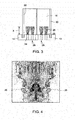
- FIG. 3 illustrated in a simplified cross-section is the combustion chamber 16 and a plurality of vortical structures 25 formed during combustion and showing a flame length of "x". Illustrated in FIG. 4 is an image of the vortical structures 25 taken during combustion. The difference in velocity will yield an internal stirring action that mixes the combustion products with the input fuel and oxidant mixture stream 28.
- the stirring action is mainly due to the large numbers of vortical structures 25 that develop around the jet 26 edges, and more particularly around a perimeter of each of the perforations or orifices 24 formed in the plate 14 or around each of the tube-like structures that form nozzle 13.
- the density of the vortical structures 25 increase with the increase in velocity ratio.
- the internal recirculation damps the NO x generation and bums CO.
- the end result is a single digit NO x and CO over a wide range of flame temperatures.
- the combustion system 10 permits reduction of the NO x concentrations based on reduction of the free oxygen radicals due to internal mixing and increased velocity. This is achieved through the increase of the reacting mixture velocity while reducing the combustion products velocity.
- the effective residence time of the combustion products is much less than the effective flame residence time. As a result, NO x production in a low oxygen environment will be suppressed.
- CO concentration will be kept low as influenced by the high firing temperature as well as the expected high degree of homogeneity.
- the high degree of homogeneity and internal mixing ensures CO bum out at low flame temperatures. This is primarily due to forcing the fresh premixed fuel and oxidant mixture stream 28 to react in the presence of hot gases.
- the concept of the present disclosure was tested on various laboratory-scale jet micro-induced flow reversals combustors. The testing was performed under substantially high pressure conditions. Illustrated in FIG. 5 is a comparison between the NO x emissions resulting from a jet micro-induced flow reversals combustor as disclosed herein operating under different high pressure conditions. Illustrated comparatively are the NO x emissions in parts per million against the flame temperature.
- the plotted points show combustion emissions data from three variations of the laboratory-scale device of the present disclosure represented by the plotted points and Curves A, B and C. Curve A is representative of a jet micro-induced flow reversals combustor according to an embodiment disclosed herein operating at approximately 300 psi.
- Curve B is representative of a jet micro-induced flow reversals combustor according to an embodiment disclosed herein operating at approximately 245 psi.
- Curve C is representative of a jet micro-induced flow reversals combustor according to an embodiment disclosed herein operating at approximately 180 psi.
- FIG. 6 illustrated in FIG. 6 is a comparison between the NO x emissions of a laboratory-scale jet micro-induced flow reversals combustors disclosed herein and the NO x emissions from a combustion device running under low velocity ratio.
- Data is represented by the plotted points that form Curve D representative of data collected from a known conventional combustor (running under low velocity ratio).
- Data is represented by the plotted points that form Curve E representative of data collected from a laboratory-scale jet micro-induced flow reversals combustor as disclosed herein.
- the curves illustrate the increase in NO x emissions at increasing flame temperatures of the combustors.
- jet micro-induced flow reversals combustor which provides low combustion emissions at elevated temperatures. More particularly, disclosed is a jet micro-induced flow reversals combustor that provides reduced NO x emissions from those currently known in the art, thereby increasing gas turbine thermal efficiency to higher levels than current combustors, increasing turndown with minimal CO penalty and enabling the use of liquid fuel while maintaining emission compliancy. While the disclosure has been illustrated and described in typical embodiments, it is not intended to be limited to the details shown, since various modifications and substitutions can be made without departing in any way from the spirit of the present disclosure. As such, further modifications and equivalents of the disclosure herein disclosed may occur to persons skilled in the art using no more than routine experimentation, and all such modifications and equivalents are believed to be within the spirit and scope of the disclosure as defined by the subsequent claims.
Landscapes
- Engineering & Computer Science (AREA)
- Chemical & Material Sciences (AREA)
- Combustion & Propulsion (AREA)
- Mechanical Engineering (AREA)
- General Engineering & Computer Science (AREA)
Applications Claiming Priority (1)
| Application Number | Priority Date | Filing Date | Title |
|---|---|---|---|
| US13/361,445 US20130196270A1 (en) | 2012-01-30 | 2012-01-30 | Jet micro-induced flow reversals combustor |
Publications (1)
| Publication Number | Publication Date |
|---|---|
| EP2620704A1 true EP2620704A1 (fr) | 2013-07-31 |
Family
ID=47631310
Family Applications (1)
| Application Number | Title | Priority Date | Filing Date |
|---|---|---|---|
| EP13152582.6A Withdrawn EP2620704A1 (fr) | 2012-01-30 | 2013-01-24 | Chambre de combustion à jet avec inversion de l'écoulement micro-induit |
Country Status (5)
| Country | Link |
|---|---|
| US (1) | US20130196270A1 (fr) |
| EP (1) | EP2620704A1 (fr) |
| JP (1) | JP2013156008A (fr) |
| CN (1) | CN103225821A (fr) |
| RU (1) | RU2013103751A (fr) |
Families Citing this family (1)
| Publication number | Priority date | Publication date | Assignee | Title |
|---|---|---|---|---|
| CN105805943A (zh) * | 2016-04-22 | 2016-07-27 | 广东三水大鸿制釉有限公司 | 一种热风烤窑装置及其使用方法 |
Citations (2)
| Publication number | Priority date | Publication date | Assignee | Title |
|---|---|---|---|---|
| US20050282097A1 (en) * | 2002-12-11 | 2005-12-22 | Elisabetta Carrea | Method for combustion of a fuel |
| JP2009014324A (ja) * | 2007-07-09 | 2009-01-22 | Hitachi Ltd | 燃焼装置及びガスタービン燃焼器 |
Family Cites Families (5)
| Publication number | Priority date | Publication date | Assignee | Title |
|---|---|---|---|---|
| US4226087A (en) * | 1979-03-01 | 1980-10-07 | United Technologies Corporation | Flameholder for gas turbine engine |
| US5687572A (en) * | 1992-11-02 | 1997-11-18 | Alliedsignal Inc. | Thin wall combustor with backside impingement cooling |
| US5437158A (en) * | 1993-06-24 | 1995-08-01 | General Electric Company | Low-emission combustor having perforated plate for lean direct injection |
| US6813889B2 (en) * | 2001-08-29 | 2004-11-09 | Hitachi, Ltd. | Gas turbine combustor and operating method thereof |
| US8919673B2 (en) * | 2010-04-14 | 2014-12-30 | General Electric Company | Apparatus and method for a fuel nozzle |
-
2012
- 2012-01-30 US US13/361,445 patent/US20130196270A1/en not_active Abandoned
-
2013
- 2013-01-24 EP EP13152582.6A patent/EP2620704A1/fr not_active Withdrawn
- 2013-01-24 JP JP2013010711A patent/JP2013156008A/ja active Pending
- 2013-01-29 RU RU2013103751/06A patent/RU2013103751A/ru not_active Application Discontinuation
- 2013-01-30 CN CN2013100350180A patent/CN103225821A/zh active Pending
Patent Citations (2)
| Publication number | Priority date | Publication date | Assignee | Title |
|---|---|---|---|---|
| US20050282097A1 (en) * | 2002-12-11 | 2005-12-22 | Elisabetta Carrea | Method for combustion of a fuel |
| JP2009014324A (ja) * | 2007-07-09 | 2009-01-22 | Hitachi Ltd | 燃焼装置及びガスタービン燃焼器 |
Also Published As
| Publication number | Publication date |
|---|---|
| CN103225821A (zh) | 2013-07-31 |
| JP2013156008A (ja) | 2013-08-15 |
| RU2013103751A (ru) | 2014-08-10 |
| US20130196270A1 (en) | 2013-08-01 |
Similar Documents
| Publication | Publication Date | Title |
|---|---|---|
| JP4658471B2 (ja) | ガスタービンエンジンの燃焼器エミッションを減少させる方法及び装置 | |
| US8261555B2 (en) | Injection nozzle for a turbomachine | |
| JP5947515B2 (ja) | 渦発生装置を有する混合管要素を備えたターボ機械 | |
| US9599343B2 (en) | Fuel nozzle for use in a turbine engine and method of assembly | |
| CN101943060B (zh) | 用于组装燃气涡轮发动机的方法、燃料喷嘴以及燃气涡轮系统 | |
| CN103185353B (zh) | 用于涡轮发动机中的燃烧器组件及其组装方法 | |
| JP6212260B2 (ja) | 燃焼器組立体内の逆火を防止するシステムおよび方法 | |
| JP5798301B2 (ja) | ガスタービンバーナ | |
| JP4997018B2 (ja) | 一次燃料噴射器及び複数の二次燃料噴射ポートを有するガスタービンエンジン燃焼器のミキサ組立体のためのパイロットミキサ | |
| JP2002039533A (ja) | 燃焼器、ガスタービン及びジェットエンジン | |
| US9261279B2 (en) | Liquid cartridge with passively fueled premixed air blast circuit for gas operation | |
| CN101900352A (zh) | 用于在涡轮中进行空气和燃料喷射的方法和装置 | |
| CN103998745B (zh) | 在燃气轮机上使用的具有分级切向燃料‑空气喷嘴的筒状环形燃烧室 | |
| CN101029739A (zh) | 组装燃气轮机的方法和设备 | |
| US8707704B2 (en) | Method and apparatus for assembling turbine engines | |
| RU2626887C2 (ru) | Тангенциальная кольцевая камера сгорания с предварительно смешанным топливом и воздухом для использования в газотурбинных двигателях | |
| RU2690598C2 (ru) | Завихритель, горелка и система сгорания для газотурбинного двигателя | |
| JP2014122784A (ja) | 燃焼器に燃料を供給するためのシステム | |
| KR102083915B1 (ko) | 연소기용 노즐, 연소기 및 이를 포함하는 가스 터빈 | |
| CN103375818A (zh) | 燃烧喷嘴及其相关方法 | |
| CN103423773A (zh) | 二次燃烧系统 | |
| US8413446B2 (en) | Fuel injector arrangement having porous premixing chamber | |
| CN103216851A (zh) | 具有弯曲部段的燃烧器喷嘴/预混器 | |
| EP3056818A2 (fr) | Nouveau procédé pour l'entrée d'air dans un revêtement afin de réduire les besoins en eau pour contrôler les nox | |
| US9851107B2 (en) | Axially staged gas turbine combustor with interstage premixer |
Legal Events
| Date | Code | Title | Description |
|---|---|---|---|
| PUAI | Public reference made under article 153(3) epc to a published international application that has entered the european phase |
Free format text: ORIGINAL CODE: 0009012 |
|
| AK | Designated contracting states |
Kind code of ref document: A1 Designated state(s): AL AT BE BG CH CY CZ DE DK EE ES FI FR GB GR HR HU IE IS IT LI LT LU LV MC MK MT NL NO PL PT RO RS SE SI SK SM TR |
|
| AX | Request for extension of the european patent |
Extension state: BA ME |
|
| 17P | Request for examination filed |
Effective date: 20140131 |
|
| RBV | Designated contracting states (corrected) |
Designated state(s): AL AT BE BG CH CY CZ DE DK EE ES FI FR GB GR HR HU IE IS IT LI LT LU LV MC MK MT NL NO PL PT RO RS SE SI SK SM TR |
|
| STAA | Information on the status of an ep patent application or granted ep patent |
Free format text: STATUS: THE APPLICATION IS DEEMED TO BE WITHDRAWN |
|
| 18D | Application deemed to be withdrawn |
Effective date: 20160802 |