EP2620771B1 - Dispositif et méthode de bioessai à concentration de particules. - Google Patents
Dispositif et méthode de bioessai à concentration de particules. Download PDFInfo
- Publication number
- EP2620771B1 EP2620771B1 EP13164976.6A EP13164976A EP2620771B1 EP 2620771 B1 EP2620771 B1 EP 2620771B1 EP 13164976 A EP13164976 A EP 13164976A EP 2620771 B1 EP2620771 B1 EP 2620771B1
- Authority
- EP
- European Patent Office
- Prior art keywords
- capillary tube
- magnetic
- spectrometer
- concentration region
- assay
- Prior art date
- Legal status (The legal status is an assumption and is not a legal conclusion. Google has not performed a legal analysis and makes no representation as to the accuracy of the status listed.)
- Active
Links
Images




Classifications
-
- G—PHYSICS
- G01—MEASURING; TESTING
- G01N—INVESTIGATING OR ANALYSING MATERIALS BY DETERMINING THEIR CHEMICAL OR PHYSICAL PROPERTIES
- G01N21/00—Investigating or analysing materials by the use of optical means, i.e. using sub-millimetre waves, infrared, visible or ultraviolet light
- G01N21/62—Systems in which the material investigated is excited whereby it emits light or causes a change in wavelength of the incident light
- G01N21/63—Systems in which the material investigated is excited whereby it emits light or causes a change in wavelength of the incident light optically excited
- G01N21/65—Raman scattering
- G01N21/658—Raman scattering enhancement Raman, e.g. surface plasmons
-
- G—PHYSICS
- G01—MEASURING; TESTING
- G01N—INVESTIGATING OR ANALYSING MATERIALS BY DETERMINING THEIR CHEMICAL OR PHYSICAL PROPERTIES
- G01N1/00—Sampling; Preparing specimens for investigation
- G01N1/28—Preparing specimens for investigation including physical details of (bio-)chemical methods covered elsewhere, e.g. G01N33/50, C12Q
- G01N1/40—Concentrating samples
-
- B—PERFORMING OPERATIONS; TRANSPORTING
- B01—PHYSICAL OR CHEMICAL PROCESSES OR APPARATUS IN GENERAL
- B01L—CHEMICAL OR PHYSICAL LABORATORY APPARATUS FOR GENERAL USE
- B01L3/00—Containers or dishes for laboratory use, e.g. laboratory glassware; Droppers
- B01L3/50—Containers for the purpose of retaining a material to be analysed, e.g. test tubes
- B01L3/508—Rigid containers without fluid transport within
- B01L3/5082—Test tubes per se
-
- B—PERFORMING OPERATIONS; TRANSPORTING
- B82—NANOTECHNOLOGY
- B82Y—SPECIFIC USES OR APPLICATIONS OF NANOSTRUCTURES; MEASUREMENT OR ANALYSIS OF NANOSTRUCTURES; MANUFACTURE OR TREATMENT OF NANOSTRUCTURES
- B82Y15/00—Nanotechnology for interacting, sensing or actuating, e.g. quantum dots as markers in protein assays or molecular motors
-
- B—PERFORMING OPERATIONS; TRANSPORTING
- B82—NANOTECHNOLOGY
- B82Y—SPECIFIC USES OR APPLICATIONS OF NANOSTRUCTURES; MEASUREMENT OR ANALYSIS OF NANOSTRUCTURES; MANUFACTURE OR TREATMENT OF NANOSTRUCTURES
- B82Y25/00—Nanomagnetism, e.g. magnetoimpedance, anisotropic magnetoresistance, giant magnetoresistance or tunneling magnetoresistance
-
- G—PHYSICS
- G01—MEASURING; TESTING
- G01N—INVESTIGATING OR ANALYSING MATERIALS BY DETERMINING THEIR CHEMICAL OR PHYSICAL PROPERTIES
- G01N15/00—Investigating characteristics of particles; Investigating permeability, pore-volume or surface-area of porous materials
- G01N2015/0092—Monitoring flocculation or agglomeration
-
- G—PHYSICS
- G01—MEASURING; TESTING
- G01N—INVESTIGATING OR ANALYSING MATERIALS BY DETERMINING THEIR CHEMICAL OR PHYSICAL PROPERTIES
- G01N21/00—Investigating or analysing materials by the use of optical means, i.e. using sub-millimetre waves, infrared, visible or ultraviolet light
- G01N21/62—Systems in which the material investigated is excited whereby it emits light or causes a change in wavelength of the incident light
- G01N21/63—Systems in which the material investigated is excited whereby it emits light or causes a change in wavelength of the incident light optically excited
- G01N21/65—Raman scattering
- G01N2021/651—Cuvettes therefore
-
- G—PHYSICS
- G01—MEASURING; TESTING
- G01N—INVESTIGATING OR ANALYSING MATERIALS BY DETERMINING THEIR CHEMICAL OR PHYSICAL PROPERTIES
- G01N35/00—Automatic analysis not limited to methods or materials provided for in any single one of groups G01N1/00 - G01N33/00; Handling materials therefor
- G01N2035/00465—Separating and mixing arrangements
- G01N2035/00524—Mixing by agitating sample carrier
-
- G—PHYSICS
- G01—MEASURING; TESTING
- G01N—INVESTIGATING OR ANALYSING MATERIALS BY DETERMINING THEIR CHEMICAL OR PHYSICAL PROPERTIES
- G01N35/00—Automatic analysis not limited to methods or materials provided for in any single one of groups G01N1/00 - G01N33/00; Handling materials therefor
- G01N35/0098—Automatic analysis not limited to methods or materials provided for in any single one of groups G01N1/00 - G01N33/00; Handling materials therefor involving analyte bound to insoluble magnetic carrier, e.g. using magnetic separation
Definitions
- the present invention is directed toward an apparatus and method for concentrating and imaging particles associated with certain assays.
- Particles and magnetic, paramagnetic or superparamagnetic particles in particular may be used in diagnostic assays as solid phase capture or detection species.
- Microparticle-based assays can be divided into two main categories: homogeneous (separation-free) and heterogeneous assays.
- homogeneous (separation-free) assay format binding reactants are mixed and measured without any subsequent washing step prior to detection.
- the advantages of such a system are fast solution-phase kinetics, a simple assay format, simpler instrumentation as well as lower costs because of fewer assay steps, low volumes and low waste.
- Homogeneous immunoassays do not require physical separation of bound and free analyte and thus may be faster and easier to perform then heterogeneous immunoassays.
- Homogeneous immunoassay systems using small sample size, low reagent volume and short incubation times provide fast turnaround time. Disadvantages of this type of assay can be limited dynamic range and sensitivity.
- Homogeneous assays are the preferred assay format in high throughput screening platforms such as AlphaScreen, SPA, fluorescent polarization and flow cytometry based assays, as well as in diagnostic assays such as particle agglutination assays with nephelometry or turbidimetry as the detection methods.
- US 2006/240,572 A1 discloses a Raman spectroscopy technique that allows an analyte, a paramagnetic particle, and a spectral enhancement particle to combine in solution and for the combination product to be localized by a magnetic field for analysis, wherein the spectral enhancement particle may be comprised of an active SERS metal particle.
- magnétique capture particles When magnetic capture particles are used in a homogeneous (separation-free) assay format, the behavior of the particles in a magnetic field can be utilized to concentrate or differentiate the magnetic particles and anything which might be bound to them from other components of the assay.
- the capture particles In assay implementations where the capture particles are bound or otherwise associated with optically labeled detection particles, it is difficult using known technologies to concentrate the capture particles at the focal plane of an optical interrogation system. Further difficulty is introduced if it is desired that the magnetic capture particles be concentrated in a relatively compact and/or small pellet for interrogation.
- the present invention is directed toward overcoming one or more of the problems discussed above.
- the present invention includes an assay apparatus comprising:
- the various embodiments of the assay apparatus described herein are suitable for use with any assay where optically labeled particles become associated with magnetic, paramagnetic or superparamagnetic capture particles.
- magnetic particles as used herein includes conventional magnetic particles, paramagnetic particles, superparamagnetic particles or any other type of particle affected by a magnetic field.
- the spectrometer is a Raman spectrometer and the optically labeled detector particles are SERS nanotags.
- the magnet (18) and the spectrometer (40) of the assay apparatus as described herein are positioned to minimize the quantity of assay fluid outside of the magnetic concentration region (20) but within an optical path between the spectrometer (40) and the magnetic concentration region (20).
- the magnet (18) is positioned to cause the magnetic concentration region (20) to be formed substantially adjacent to a location where an optical path between the spectrometer (40) and the magnetic concentration region (20) initially intersects the interior of the capillary tube (52).
- an intermediate step of moving the sample vessel from the holder/concentrator to a separate spectrometer is eliminated.
- the first advantage is improved accuracy in placing the magnetic particles (or defining the magnetic concentration region) within the sample vessel, such that measurement repeatability is improved, and the possibility for false negative results (missing the concentrated pellet of magnetic particles altogether) is avoided.
- the second advantage concerns eliminating the step of moving the sample vessel from the holder/concentrator to a separate spectrometer, thus sample reading is reduced to a single step operation. Furthermore, the associated risk of movement of the pellet within the sample vessel or disassociation of the pellet during transfer to the spectrometer, which may cause errors in measurement, is eliminated.
- the assay apparatus may further comprise means to stimulate compact concentration operatively associated with the capillary tube (52).
- the means to stimulate compact concentration is selected from a group consisting of an electromagnetic stimulator; a vibrator; an acoustic transducer and a mechanical agitator.
- the present invention describes a method of performing an assay comprising :
- magnetic particles shall be defined as conventional magnetic particles, paramagnetic particles, superparamagnetic particles or any other particle which is affected by a magnetic field.
- advantages may be realized by having magnetic capture and concentration apparatus integrated with a spectrometer or other optical interrogation device. For example a fully integrated capture, concentration and imaging system minimizes the possibility of the misplacement or de-compaction of a pellet of concentrated magnetic particles since the sample vessel does not have to be moved between the concentration and optical interrogation steps. Accordingly, such integrated apparatus embodiments are described in detail below.
- any other suitable shape and relative size of magnets which may be either permanent magnets or electromagnets, are equally suitable for implementation of the present invention.
- a linear magnet may be used to provide for a linear pellet which may be scanned along a length.
- capillay tubes (52) having any number of customized shapes may be used to effectively implement the apparatus.
- the customized shape might include a protrusion or indentation or other structure or form at or near the magnetic concentration region 20 described above.
- the customized shape may affect the nature of the pellet formed in the concentration step.
- the development of a concentrated, well-formed, and consistent magnetic pellet from magnetic capture particles and associated optical labels is a function of the magnetic field architecture as well as the sample tube morphology at the magnetic concentration region 20.
- the size and shape of the concentrated pellet can be altered by altering the shape of the surface the magnetic capture particles are collected upon or within.
- customized tube architecture with a dimple (or cusp) or other shaped structure or form at or near the magnetic concentration region could aid in the formation of a magnetic pellet having reproducible size, shape and consistency.
- a concave cusp may be utilized to form a spherical pellet at the bottom or side of a customized collection vessel.
- the material of the capillay tubes (52) must be compatible with the reagents and analyte substances intended for use in the assay. Certain chemical or biological coatings may be applied to the vessel to prevent non specific binding of magnetic particles, optical tag or analyte to the vessel walls.
- the capillay tube (52) should be constructed of a non-magnetic material, such that a magnetic field applied from an external source passes through the capillay tube (52) unaffected. Furthermore, it should be designed such that consideration is given to the maximum distance that would be travelled by reagents to the localisation spot. This governs the speed and efficacy of magnetic capture, since the attractive force decreases rapidly as the distance from the magnet system is increased.
- the form of the capillay tube (52) may include external geometric features, markers or indicia 22, to enhance the repeatability of positioning, and prevent incorrect vessel insertion within the holder apparatus.
- Positioning features could include (but are not limited to) the inclusion of flat sections, keyways, fiducial points etc. These would match similar features in a specifically designed vessel receptacle associated with magnetic localisation, spectroscopic measurement or combination of these functions, all as described herein.
- the capillay tube (52) should be appreciably transparent in the desired laser interrogation wavelength region. Moreover, it is desirable to ensure that the localising region has optical properties compatible with the lens system of the spectrometer or other detection device. Flat optical surfaces that allow the entry and exit of excitation and emitted light with minimal refraction, reflection or scattering may be desired. Alternatively, surfaces with curvature in one or more dimensions intended to function as lenses may be beneficial. Furthermore, the vessel design should allow the simultaneous presence of a magnetic localising system and operation of the spectrometer in the case where both functions are included in one instrument. The magnetic concentration region 20 can be at any position on the capillay tube (52) conducive to the ability to concentrate and localise the assay reagents and make optical measurements.
- SERS nanotags have a SERS active core associated with a Raman reporter molecule which may be interrogated through Raman spectroscopy. Accordingly, it is useful in any implementation of the present invention which features Raman spectroscopy that the material of the capillay tube (52) be transparent to Raman light scatter.
- the primary limitation with respect to Raman spectroscopy is that the capillay tube (52) wall not interfere through absorption both at the laser excitation wavelengths, including, but not limited to, 633nm or 785 nm wavelengths, as well as the subsequent Raman emission wavelengths. Indeed, an ideal material would also not contribute Raman interference and/or fluorescence at these excitation wavelengths, as well.
- a wide variety of inexpensive and commonly used assay tubes meet this criteria.
- Graph 46 of Fig. 1 illustrates the progress of pellet formation during magnetic concentration as a function of time, as determined by the signal from SERS labels attached to magnetic beads in an immunological reaction scheme. It is desirable for spectroscopic analysis that the pellet size be as small as possible, since an appreciable part of the volume of captured particles may otherwise fall outside the laser illumination spot presented by typical instruments, which is generally a diameter of about 70 to 200 microns. It is also desirable that the pellet size be as small as possible for a given number of magnetic beads. This has multiple advantages. First, a dense pellet results in a smaller sampling area.
- a denser pellet results in a higher signal-to-noise ratio as there will be a larger number of tags per unit sampling volume.
- a denser pellet should also improve sample-to-sample variance as a smaller pellet should match better to both the laser spot and optical collection area.
- a collection area which is slightly larger than the pellet should be relatively immune to signal variations from minor shape differences between pellets.
- a dense pellet of magnetic beads aids in obscuring the larger volume of solution, containing unbound optical label. This mechanism of obscuration could lower the detection floor, thus increasing sensitivity and leading to an improvement in the dynamic range of the test.
- Pellet formation can be achieved with a static positioning between the capillay tube (52) and magnet 18.
- the magnetic particles may be concentrated to a smaller volume if the magnet 18 is moved relative to the surface of the sample vessel - a displacement of less than 1mm is sufficient to achieve measurable concentration improvement. Movement of the magnet 18, however, may be impractical, due to the requirement that the position of the magnetic concentration zone 20 be in coincidence with the laser illumination from the spectrometer 40. It is possible to stimulate tight pellet formation however, by use of techniques or methods including but not limited to mechanical, acoustic or magnetic stimulation of the capillay tube (52). Vibrational energy is sufficient to dislodge particles that have become stuck to the vessel wall before reaching the final position of lowest potential energy nearest the magnet 18 or magnetic pole piece 44.
- step (a) is the initial capture of reagents from the starting point of complete dispersion in the assay fluid
- step (b) is the completion of initial capture and pellet formation
- step (c) involves forcing the pellet to reform and concentrate at a second capture point without significant redispersion. This can be achieved by:
- an integrated capture/interrogation unit it may be challenging to design a magnetic assembly which generates a strong enough magnetic field to pull magnetic particles down through the assay solution, to form a suitable pellet, and also provide clearance for the optical read-out.
- any curvature of the capillay tube (52) plus optical effects of assay components contained therein may act as an optical element. It is desirable as described above to achieve a small illumination spot and collection area. Accordingly, the optical system associated with the spectrometer 40 may be designed to compensate for the optical effects of the capillay tube (52).
- Figs. 3-5 show single capillay tubes (52), high throughput parallel assays can easily be prepared and performed by using multiple parallel assay capillay tubes holders and magnets.
- the magnetic concentrator step and readout could occur in parallel or serially.
- a 1 ⁇ 2" spherical NdFeB (rare-earth) magnet has been successfully used experimentally to create a pellet of magnetic beads and associated SERS tags in a single pull-down step.
- the capillay tube (52) used was a 200uL polypropylene microcentrifuge tube with 100uL or less of reagent. As shown on graph 46 of Fig. 1 , adequate pull-down of particles leading to a relatively steady state optical signal was achieved in less than one minute.
- a whole pellet may be imaged using a tunable filter (LCTF, AOTF, etc.) to create a hyper-spectral image stack. If consistent pellet formation proves to be difficult, imaging the whole pellet combined with subsequent image analysis could provide a metric for a "total optical label" that is consistent without respect to the distribution or shape of the pellet.
- LCTF tunable filter
- AOTF AOTF
- a diffuse pellet for example a linear pellet formed by a linear magnet
- the pellet may be imaged and a software analysis step employed to determine a metric for the total signal (for example the SERS signal) emitted by each pellet.
- This implementation shares features with DNA microarray readers commonly available, except for the need for a relatively large number of spectral channels (i.e. hyperspectral imaging). Nonetheless, for a high-throughput system utilizing a microplate configuration with multiple wells, this could offer benefits.
- Optical resolution on the order of 50um, could be adequate to allow an image processing algorithm to account for pellet size and shape differences to obtain a consistent total signal metric across replicate pellets.
- a minimum number of spectral channels ⁇ 20-30 spectral channels
- this may provide for the use of liquid-crystal tunable filters (LCTF), or acousto-optical tunable filters (AOTF) to achieve spectral separation.
- LCTF liquid-crystal tunable filters
- AOTF acousto-optical tunable filters
- Magnetic concentration freezes the chemical reaction and so all samples in a batch would require that their pellets be formed at the same time. Large process volumes may result in variation in the exact location of each pellet.
- An image processing step could extract the positions of all the pellets and use this information to position a conventional point spectrometer system under each pellet sequentially.
- High throughput apparatus could be fabricated in which the capillay tubes are discrete tubes.
- the tubes could be transported within the apparatus to various function "stations" by a conveyor track, belt or robotic system.
- the precise location and timing of each sample tube could be tracked by a microprocessor system that controls the apparatus function, enabling precise control of reaction timings, temperatures, mixing and measurement etc.
- Such an apparatus for the invention might include provision for process steps including but not limited to
- the sequence of steps could include the methods of localisation separate from, or coincident with making optical measurements, in the same manner as described already, thus the high throughput apparatus would incorporate receptacles for the vessels that have magnet assemblies for localisation, and/or spectrometers operatively associated with magnet assemblies.
- Other variations upon the basic high throughput apparatus described herein are within the scope of this disclosure.
- a small bead composed of a material of high magnetic permeability e.g. nickel, cobalt, etc
- the presence of the high-permeability bead will focus the magnetic field lines thus creating a high magnetic field gradient to attract the magnetic particles.
- the magnetic particle / assay tag complex could associate around the bead and the whole large assembly, consisting of a large "bead" with the surrounding small magnetic particles and assay tags would be imaged. This technique could assist in achieving a reproducible spherical pellet for optimal interrogation.
- the apparatus 50 includes a capillary tube 52.
- the capillary tube 52 is in fluid communication with an assay particle suspension 54.
- an assay particle suspension 54 As the particle suspension 54 flows through the capillary tube 52, magnetic particles are concentrated within the tube 52 by a capture magnet 18 which may or may not be associated with a pole piece 44.
- the capture magnet 18 serves to concentrate magnetic particles at a specific magnetic concentration region 20 within the capillary tube 52.
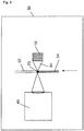
- a spectrometer or other interrogation device which may be a Raman spectrometer 40 is operatively associated with the capillary tube 52 and focused upon the magnetic concentration region 20. As shown in Figs. 3 and 4 , optical interrogation may occur along an optical path which is opposite from or merely offset from the magnetic axis.
- capillary tube 52 as a sample vessel provides several distinct advantages including but are not limited to:
- the capillary tube-based lateral flow embodiment described immediately above is suitable for use as an integrated assay system which could if desired be developed in a very compact form factor for highly accurate and repeatable field assay usage.
- An integrated system 60 consistent with this embodiment is schematically illustrated in Fig. 5 .
- the capillary tube 52 is mounted in a sample cartridge 62.
- the capillary tube 52 is in communication with a sample reservoir 64 formed in the sample cartridge 62.
- the assay particle suspension 54 necessary to perform an assay including magnetic particles and reagents may be mixed in the sample reservoir 64. Since the sample reservoir 64 is in fluid communication with the capillary tube 52, fully reacted assay suspension 54 is readily drawn toward the magnetic concentration region 20 by capillary action. In addition, excess assay particles are wicked away from the magnetic concentration region 20 minimizing background signal.
- a magnet 18 will concentrate magnetic particles as described above at the focal plane of a spectrometer 40 where optical interrogation of the concentrated sample may occur.
- the integrated system 60 of Fig. 5 may be fabricated with a cartridge docking receptacle 66 configured to accurately receive and position the cartridge 62 so that the magnetic capture region 20 is properly aligned.
- the system 60 may also include data processing elements 68 associated with the spectrometer that enable the apparatus 60 to be used as a portable and potentially handheld stand-alone assay device.
Landscapes
- Health & Medical Sciences (AREA)
- General Physics & Mathematics (AREA)
- Pathology (AREA)
- Life Sciences & Earth Sciences (AREA)
- Chemical & Material Sciences (AREA)
- Analytical Chemistry (AREA)
- Biochemistry (AREA)
- Physics & Mathematics (AREA)
- Immunology (AREA)
- General Health & Medical Sciences (AREA)
- Nuclear Medicine, Radiotherapy & Molecular Imaging (AREA)
- Investigating, Analyzing Materials By Fluorescence Or Luminescence (AREA)
- Sampling And Sample Adjustment (AREA)
- Other Investigation Or Analysis Of Materials By Electrical Means (AREA)
- Investigating Or Analysing Materials By Optical Means (AREA)
- Automatic Analysis And Handling Materials Therefor (AREA)
Claims (13)
- Appareil de dosage (60) comprenant :un tube capillaire (52) ;un réservoir d'échantillon (64) ;une cartouche d'échantillon (62) dans laquelle est formé le réservoir d'échantillon (64) et dans laquelle est monté le tube capillaire (52), moyennant quoi le tube capillaire (52) est en communication fluidique avec le réservoir (64) ;un support (66) conçu pour recevoir la cartouche d'échantillon (62) ;un aimant (18) associé fonctionnellement au support (66) de telle sorte qu'un champ magnétique croise une partie du tube capillaire (52) en définissant une région de concentration magnétique (20) au sein du tube capillaire (52) ; etun spectromètre (40) associé fonctionnellement au support (66) de telle sorte que la mise au point du spectromètre (40) se trouve au sein de la région de concentration magnétique (20).
- Appareil de dosage selon la revendication 1, dans lequel le spectromètre (40) est un spectromètre Raman.
- Appareil de dosage selon l'une quelconque des revendications 1 ou 2, comprenant en outre un moyen de stimuler une concentration compacte associé fonctionnellement au tube capillaire (52) ;
de préférence dans lequel le moyen de stimuler une concentration compacte est choisi parmi un groupe constitué d'un stimulateur électromagnétique ; un vibrateur ; un transducteur acoustique et un agitateur mécanique. - Appareil de dosage selon l'une quelconque des revendications 1 à 3, dans lequel l'aimant (18) et le spectromètre (40) sont positionnés de façon à minimiser la quantité de fluide de dosage à l'extérieur de la région de concentration magnétique (20), mais au sein d'une trajectoire optique entre le spectromètre (40) et la région de concentration magnétique (20).
- Appareil de dosage selon l'une quelconque des revendications 1 à 4, dans lequel l'aimant (18) est positionné pour amener la région de concentration magnétique (20) à être formée essentiellement adjacente à un emplacement où une trajectoire optique entre le spectromètre (40) et la région de concentration magnétique (20) croise initialement l'intérieur du tube capillaire (52).
- Appareil de dosage selon l'une quelconque des revendications 1 à 5, dans lequel le tube capillaire (52) comprend en outre une paroi interne, dans lequel une partie de la paroi interne qui est initialement croisée par une trajectoire optique du spectromètre (40) définit une interface et dans lequel la région de concentration magnétique (20) est formée essentiellement adjacente à l'interface.
- Procédé d'exécution d'un dosage comprenant :l'association de particules magnétiques de capture à des particules de détection dans un tube capillaire (52) d'une cartouche d'échantillon (62) dans laquelle est formé un réservoir d'échantillon (64) et dans laquelle est monté le tube capillaire (52), moyennant quoi le tube capillaire (52) est en communication fluidique avec le réservoir (64) ;la mise en place de la cartouche d'échantillon (62) dans un support (66) conçu pour recevoir la cartouche d'échantillon (62) et la maintenir dans une relation sélectionnée avec un aimant (18) et un spectromètre (40) associé au support ;la concentration par voie magnétique des particules magnétiques de capture dans une région de concentration (20) du tube capillaire (52) de telle sorte que la mise au point du spectromètre (40) se trouve au sein de la région de concentration magnétique (20) ;et l'obtention d'un spectre à partir de la région de concentration magnétique (20).
- Procédé selon la revendication 7, dans lequel le spectre obtenu à partir de la région de concentration magnétique (20) est un spectre Raman, de préférence dans lequel le spectre Raman est obtenu à partir d'un traceur SERS associé aux particules magnétiques de capture dans la région de concentration magnétique (20).
- Procédé d'exécution d'un dosage selon l'une quelconque des revendications 7 à 8, comprenant en outre la stimulation d'une concentration compacte des particules magnétiques de capture dans la région de concentration (20) ;
de préférence dans lequel l'étape de stimulation comprend au moins une opération parmi une agitation mécanique du tube capillaire (52) ; une vibration du tube capillaire (52) ; la projection d'une onde acoustique à travers le tube capillaire (52) et le passage d'un champ magnétique mobile à travers une partie du tube capillaire (52). - Procédé d'exécution d'un dosage selon l'une quelconque des revendications 7 à 9, dans lequel l'aimant (18) et le spectromètre (40) sont positionnés de façon à minimiser la quantité de fluide de dosage à l'extérieur de la région de concentration magnétique (20), mais au sein d'une trajectoire optique entre le spectromètre (40) et la région de concentration magnétique (20).
- Procédé d'exécution d'un dosage selon l'une quelconque des revendications 7 à 10, dans lequel l'aimant (18) est positionné pour amener la région de concentration magnétique (20) à être formée essentiellement adjacente à un emplacement où une trajectoire optique entre le spectromètre (40) et la région de concentration magnétique (20) croise initialement l'intérieur du tube capillaire (52).
- Procédé d'exécution d'un dosage selon l'une quelconque des revendications 7 à 11, dans lequel le tube capillaire (52) comprend en outre une paroi interne, dans lequel une partie de la paroi interne qui est initialement croisée par une trajectoire optique provenant du spectromètre (40) définit une interface et dans lequel la région de concentration magnétique (20) est formée essentiellement adjacente à l'interface.
- Procédé d'exécution d'un dosage selon l'une quelconque des revendications 9 à 12, dans lequel l'étape de stimulation comprend au moins une opération parmi un repositionnement du tube capillaire (52) par rapport à l'aimant (18) ; un repositionnement de l'aimant (18) par rapport au tube capillaire (52) et l'application d'un champ magnétique depuis plus d'un aimant (18) vers le tube capillaire (52).
Applications Claiming Priority (4)
| Application Number | Priority Date | Filing Date | Title |
|---|---|---|---|
| US83292106P | 2006-07-24 | 2006-07-24 | |
| US91025607P | 2007-04-05 | 2007-04-05 | |
| US91024607P | 2007-04-05 | 2007-04-05 | |
| EP07799772.4A EP2044402B2 (fr) | 2006-07-24 | 2007-07-24 | Dispositif et procédé pour réaliser un dosage avec des particules magnétiques |
Related Parent Applications (3)
| Application Number | Title | Priority Date | Filing Date |
|---|---|---|---|
| EP07799772.4A Division-Into EP2044402B2 (fr) | 2006-07-24 | 2007-07-24 | Dispositif et procédé pour réaliser un dosage avec des particules magnétiques |
| EP07799772.4A Division EP2044402B2 (fr) | 2006-07-24 | 2007-07-24 | Dispositif et procédé pour réaliser un dosage avec des particules magnétiques |
| EP07799772.4 Division | 2007-07-24 |
Publications (2)
| Publication Number | Publication Date |
|---|---|
| EP2620771A1 EP2620771A1 (fr) | 2013-07-31 |
| EP2620771B1 true EP2620771B1 (fr) | 2017-08-30 |
Family
ID=38982246
Family Applications (2)
| Application Number | Title | Priority Date | Filing Date |
|---|---|---|---|
| EP13164976.6A Active EP2620771B1 (fr) | 2006-07-24 | 2007-07-24 | Dispositif et méthode de bioessai à concentration de particules. |
| EP07799772.4A Active EP2044402B2 (fr) | 2006-07-24 | 2007-07-24 | Dispositif et procédé pour réaliser un dosage avec des particules magnétiques |
Family Applications After (1)
| Application Number | Title | Priority Date | Filing Date |
|---|---|---|---|
| EP07799772.4A Active EP2044402B2 (fr) | 2006-07-24 | 2007-07-24 | Dispositif et procédé pour réaliser un dosage avec des particules magnétiques |
Country Status (5)
| Country | Link |
|---|---|
| US (1) | US20100060893A1 (fr) |
| EP (2) | EP2620771B1 (fr) |
| JP (1) | JP5277165B2 (fr) |
| ES (2) | ES2422295T5 (fr) |
| WO (1) | WO2008014223A2 (fr) |
Families Citing this family (23)
| Publication number | Priority date | Publication date | Assignee | Title |
|---|---|---|---|---|
| AU2009296526B2 (en) * | 2008-09-24 | 2015-11-19 | First Light Diagnostics, Inc. | Method for detecting analytes |
| EP2380001B1 (fr) * | 2008-12-18 | 2015-02-11 | Azbil Corporation | Détecteur compact pour la détection simultanée de la taille et de la fluorescence de particules |
| US8828729B1 (en) | 2009-01-28 | 2014-09-09 | Cabot Corporation | Methods and apparatus for the detection of taggants by surface enhanced raman scattering |
| WO2012078801A2 (fr) * | 2010-12-07 | 2012-06-14 | Voorhees Kent J | Détection d'analytes concentrés par un champ magnétique dans un capillaire à écoulement latéral |
| US8624199B2 (en) | 2011-10-28 | 2014-01-07 | Fei Company | Sample block holder |
| EP3254762B1 (fr) * | 2012-04-12 | 2020-04-29 | Becton Dickinson and Company | Procédés, systèmes et dispositifs de détection et d'identification de micro-organismes dans des échantillons de culture microbiologique |
| USD690826S1 (en) | 2012-04-12 | 2013-10-01 | Becton Dickinson And Company | Vessel assembly |
| US8664595B2 (en) | 2012-06-28 | 2014-03-04 | Fei Company | Cluster analysis of unknowns in SEM-EDS dataset |
| US9188555B2 (en) | 2012-07-30 | 2015-11-17 | Fei Company | Automated EDS standards calibration |
| US9091635B2 (en) | 2012-10-26 | 2015-07-28 | Fei Company | Mineral identification using mineral definitions having compositional ranges |
| US9048067B2 (en) | 2012-10-26 | 2015-06-02 | Fei Company | Mineral identification using sequential decomposition into elements from mineral definitions |
| US8937282B2 (en) | 2012-10-26 | 2015-01-20 | Fei Company | Mineral identification using mineral definitions including variability |
| US9778215B2 (en) | 2012-10-26 | 2017-10-03 | Fei Company | Automated mineral classification |
| US9194829B2 (en) | 2012-12-28 | 2015-11-24 | Fei Company | Process for performing automated mineralogy |
| EP3105565B1 (fr) | 2014-02-11 | 2020-12-23 | Wallac OY | Dispositif et procédé de gestion d'échantillon à analyser, et porteur d'échantillon solide et porteur d'échantillon liquide |
| ITUB20154940A1 (it) * | 2015-11-06 | 2017-05-06 | Disa Raffaele E F Lli S A S | Cella per analisi mediante spettroscopia Raman. |
| CN119056579A (zh) | 2016-03-18 | 2024-12-03 | 安德鲁联合有限公司 | 液体处理器的尖端中的珠子操作方法及装置 |
| EP3642625A4 (fr) * | 2017-06-20 | 2021-06-09 | Salus Discovery, LLC | Dispositifs et procédés d'écoulement latéral |
| GB201818412D0 (en) * | 2018-11-12 | 2018-12-26 | Lumiradx Tech Ltd | A magnetic assembly for use in a device for conducting assays |
| WO2021198959A1 (fr) * | 2020-04-03 | 2021-10-07 | Andrew Alliance S.A. | Manipulation de billes dans un consommable |
| US11480565B2 (en) | 2020-06-12 | 2022-10-25 | Bio-Rad Laboratories, Inc. | Automated immunoassay |
| EP4507831A1 (fr) * | 2022-04-15 | 2025-02-19 | Quantoom Biosciences S.A. | Dispositif et procédé de séparation et/ou de purification d'un composé d'intérêt |
| BE1030466B1 (fr) * | 2022-04-20 | 2023-11-21 | Quantoom Biosciences S A | Dispositif et méthode pour la séparation et/ou la purification d’un composé d’intérêt |
Citations (1)
| Publication number | Priority date | Publication date | Assignee | Title |
|---|---|---|---|---|
| US5238810A (en) * | 1986-09-22 | 1993-08-24 | Nippon Telegraph And Telephone Corporation | Laser magnetic immunoassay method and apparatus thereof |
Family Cites Families (87)
| Publication number | Priority date | Publication date | Assignee | Title |
|---|---|---|---|---|
| US4039297A (en) * | 1971-12-25 | 1977-08-02 | Japanese National Railways | Heat insulating particles |
| GB1452271A (en) * | 1972-10-23 | 1976-10-13 | English Clays Lovering Pochin | Apparatus for use in separating magnetic particles from a fluid in which they are suspended |
| US3975084A (en) * | 1973-09-27 | 1976-08-17 | Block Engineering, Inc. | Particle detecting system |
| NL7807532A (nl) * | 1978-07-13 | 1980-01-15 | Akzo Nv | Metaal-immunotest. |
| GB8415998D0 (en) * | 1984-06-22 | 1984-07-25 | Janssen Pharmaceutica Nv | Staining method |
| US5059394A (en) * | 1986-08-13 | 1991-10-22 | Lifescan, Inc. | Analytical device for the automated determination of analytes in fluids |
| JPS63106559A (ja) * | 1986-10-23 | 1988-05-11 | Nippon Telegr & Teleph Corp <Ntt> | レ−ザ磁気免疫測定方法及び装置 |
| US4802761A (en) * | 1987-08-31 | 1989-02-07 | Western Research Institute | Optical-fiber raman spectroscopy used for remote in-situ environmental analysis |
| US4853335A (en) * | 1987-09-28 | 1989-08-01 | Olsen Duane A | Colloidal gold particle concentration immunoassay |
| US5238811A (en) * | 1988-04-26 | 1993-08-24 | Nippon Telegraph And Telephone Corporation | Laser magnetic immunoassay method and apparatus therefor and superparamagnetic material-labeled body and method for the manufacture of same |
| JP2551627B2 (ja) * | 1988-04-26 | 1996-11-06 | 日本電信電話株式会社 | レーザ磁気免疫測定装置 |
| US5096809A (en) * | 1988-07-25 | 1992-03-17 | Pacific Biotech, Inc. | Whole blood assays using porous membrane support devices |
| US5023139A (en) * | 1989-04-04 | 1991-06-11 | Research Corporation Technologies, Inc. | Nonlinear optical materials |
| DE3934351A1 (de) * | 1989-10-14 | 1991-04-18 | Studiengesellschaft Kohle Mbh | Verfahren zur herstellung von mikrokristallinen bis amorphen metall- bzw. legierungspulvern und ohne schutzkolloid in organischen solventien geloesten metallen bzw. legierungen |
| US5112127A (en) * | 1989-11-28 | 1992-05-12 | Eic Laboratories, Inc. | Apparatus for measuring Raman spectra over optical fibers |
| US5255067A (en) * | 1990-11-30 | 1993-10-19 | Eic Laboratories, Inc. | Substrate and apparatus for surface enhanced Raman spectroscopy |
| JPH04348277A (ja) | 1991-05-24 | 1992-12-03 | Nippon Paint Co Ltd | 生体内物質の測定方法及び測定装置 |
| US6200820B1 (en) * | 1992-12-22 | 2001-03-13 | Sienna Biotech, Inc. | Light scatter-based immunoassay |
| US5384265A (en) * | 1993-03-26 | 1995-01-24 | Geo-Centers, Inc. | Biomolecules bound to catalytic inorganic particles, immunoassays using the same |
| US5637508A (en) * | 1993-03-26 | 1997-06-10 | Geo-Centers, Inc. | Biomolecules bound to polymer or copolymer coated catalytic inorganic particles, immunoassays using the same and kits containing the same |
| JPH06300762A (ja) * | 1993-04-14 | 1994-10-28 | Nippon Telegr & Teleph Corp <Ntt> | 非分離型蛍光免疫測定装置 |
| US5441894A (en) * | 1993-04-30 | 1995-08-15 | Abbott Laboratories | Device containing a light absorbing element for automated chemiluminescent immunoassays |
| CA2164725A1 (fr) * | 1993-06-08 | 1994-12-22 | Alexander Saunders | Methode de mesure optique en deux phases et appareil connexe |
| US7141212B2 (en) * | 1993-11-12 | 2006-11-28 | Inverness Medical Switzerland Gmbh | Reading devices and assay devices for use therewith |
| SG72684A1 (en) * | 1993-11-12 | 2000-05-23 | Unipath Ltd | Reading devices and assay devices for use therewith |
| JP3115501B2 (ja) * | 1994-06-15 | 2000-12-11 | プレシジョン・システム・サイエンス株式会社 | 分注機を利用した磁性体の脱着制御方法及びこの方法によって処理される各種装置 |
| US6451619B1 (en) * | 1994-06-29 | 2002-09-17 | Inverness Medical Switzerland Gmbh | Monitoring methods and devices for use therein |
| EP0804732B1 (fr) * | 1995-01-16 | 2001-10-10 | SOINI, Erkki | Procede de dosage multiparametrique biospecifique |
| WO1996026011A1 (fr) * | 1995-02-21 | 1996-08-29 | Siddiqi Iqbal W | Appareil et procede de melange et de separation a l'aide de particules magnetiques |
| JPH09218201A (ja) * | 1995-12-07 | 1997-08-19 | Seiko Instr Inc | 磁性粒子の分離方法 |
| US5833924A (en) * | 1995-12-22 | 1998-11-10 | Universal Healthwatch, Inc. | Sampling-assay device and interface system |
| US6750031B1 (en) * | 1996-01-11 | 2004-06-15 | The United States Of America As Represented By The Secretary Of The Navy | Displacement assay on a porous membrane |
| US6027890A (en) * | 1996-01-23 | 2000-02-22 | Rapigene, Inc. | Methods and compositions for enhancing sensitivity in the analysis of biological-based assays |
| AUPN825796A0 (en) * | 1996-02-26 | 1996-03-14 | Ashdown, Martin | The application of infrared (ir) spectrometry to the investigations of components of blood and other body fluids |
| US6103868A (en) * | 1996-12-27 | 2000-08-15 | The Regents Of The University Of California | Organically-functionalized monodisperse nanocrystals of metals |
| US5958704A (en) * | 1997-03-12 | 1999-09-28 | Ddx, Inc. | Sensing system for specific substance and molecule detection |
| US5998224A (en) * | 1997-05-16 | 1999-12-07 | Abbott Laboratories | Magnetically assisted binding assays utilizing a magnetically responsive reagent |
| US6558956B1 (en) * | 1997-06-24 | 2003-05-06 | The University Of Wyoming | Method and apparatus for detection of a controlled substance |
| US5864397A (en) * | 1997-09-15 | 1999-01-26 | Lockheed Martin Energy Research Corporation | Surface-enhanced raman medical probes and system for disease diagnosis and drug testing |
| US6060256A (en) * | 1997-12-16 | 2000-05-09 | Kimberly-Clark Worldwide, Inc. | Optical diffraction biosensor |
| US6020207A (en) * | 1998-06-17 | 2000-02-01 | World Precision Instruments, Inc. | Optical analysis technique and sensors for use therein |
| US6226082B1 (en) * | 1998-06-25 | 2001-05-01 | Amira Medical | Method and apparatus for the quantitative analysis of a liquid sample with surface enhanced spectroscopy |
| US6136610A (en) * | 1998-11-23 | 2000-10-24 | Praxsys Biosystems, Inc. | Method and apparatus for performing a lateral flow assay |
| US6150182A (en) † | 1998-11-30 | 2000-11-21 | Cassaday; Michael M. | Method for separation of components in a biochemical reaction utilizing a combination of magnetic and centrifugal processes |
| EP1151139A2 (fr) * | 1999-01-25 | 2001-11-07 | UT-Battelle, LLC | Biocapteurs mulitispectre et multifonctions, et leurs procedes d'utilisation |
| DE60041255D1 (de) * | 1999-04-28 | 2009-02-12 | Eidgenoess Tech Hochschule | Polyionische beschichtungen für analytische und sensor-vorrichtungen |
| US6274323B1 (en) * | 1999-05-07 | 2001-08-14 | Quantum Dot Corporation | Method of detecting an analyte in a sample using semiconductor nanocrystals as a detectable label |
| US7123359B2 (en) * | 1999-05-17 | 2006-10-17 | Arrowhead Center, Inc. | Optical devices and methods employing nanoparticles, microcavities, and semicontinuous metal films |
| US6730400B1 (en) * | 1999-06-15 | 2004-05-04 | Teruo Komatsu | Ultrafine composite metal particles and method for manufacturing same |
| US7105310B1 (en) * | 2000-07-19 | 2006-09-12 | California Institute Of Technology | Detection of biomolecules by sensitizer-linked substrates |
| DE60023998T2 (de) * | 1999-07-30 | 2006-08-10 | Mitsubishi Chemical Corp. | Immunoassay |
| US6422998B1 (en) * | 1999-09-20 | 2002-07-23 | Ut-Battelle, Llc | Fractal analysis of time varying data |
| US6645777B1 (en) * | 1999-11-05 | 2003-11-11 | The Board Of Governors For Higher Education, State Of Rhode Island And Providence Plantation | Tapered tubular optical waveguide probe for magnetic focusing immunosensors |
| US6254830B1 (en) * | 1999-11-05 | 2001-07-03 | The Board Of Governors For Higher Education, State Of Rhode Island And Providence Plantations | Magnetic focusing immunosensor for the detection of pathogens |
| US6587197B1 (en) * | 1999-12-06 | 2003-07-01 | Royce Technologies Llc | Multiple microchannels chip for biomolecule imaging, and method of use thereof |
| EP2365096A1 (fr) * | 2000-03-22 | 2011-09-14 | Life Technologies Corporation | Procédés d'utilisation de nano-cristaux semi-conducteurs dans des analyses d'acide nucléique de billes |
| US6734420B2 (en) * | 2000-04-06 | 2004-05-11 | Quantum Dot Corporation | Differentiable spectral bar code methods and systems |
| AU2001250287B2 (en) * | 2000-04-11 | 2005-06-23 | Chemometec A/S | Method and apparatus for detecting fluorescence of a sample |
| US6610351B2 (en) * | 2000-04-12 | 2003-08-26 | Quantag Systems, Inc. | Raman-active taggants and their recognition |
| WO2001083823A1 (fr) * | 2000-04-28 | 2001-11-08 | Quantum Dot Corporation | Procedes et compositions pour l'analyse de polynucleotides au moyen de sequences de capture generiques |
| US6649138B2 (en) * | 2000-10-13 | 2003-11-18 | Quantum Dot Corporation | Surface-modified semiconductive and metallic nanoparticles having enhanced dispersibility in aqueous media |
| US20020083888A1 (en) * | 2000-12-28 | 2002-07-04 | Zehnder Donald A. | Flow synthesis of quantum dot nanocrystals |
| WO2003092043A2 (fr) * | 2001-07-20 | 2003-11-06 | Quantum Dot Corporation | Nanoparticules luminescentes et techniques de preparation |
| US6972173B2 (en) * | 2002-03-14 | 2005-12-06 | Intel Corporation | Methods to increase nucleotide signals by raman scattering |
| US6562403B2 (en) * | 2001-10-15 | 2003-05-13 | Kansas State University Research Foundation | Synthesis of substantially monodispersed colloids |
| US6778316B2 (en) * | 2001-10-24 | 2004-08-17 | William Marsh Rice University | Nanoparticle-based all-optical sensors |
| US7098041B2 (en) * | 2001-12-11 | 2006-08-29 | Kimberly-Clark Worldwide, Inc. | Methods to view and analyze the results from diffraction-based diagnostics |
| US7102752B2 (en) * | 2001-12-11 | 2006-09-05 | Kimberly-Clark Worldwide, Inc. | Systems to view and analyze the results from diffraction-based diagnostics |
| US20040021073A1 (en) * | 2002-04-12 | 2004-02-05 | California Institute Of Technology | Apparatus and method for magnetic-based manipulation of microscopic particles |
| JP3983593B2 (ja) * | 2002-04-26 | 2007-09-26 | プレシジョン・システム・サイエンス株式会社 | 磁性粒子懸濁液測定装置 |
| US20030211488A1 (en) * | 2002-05-07 | 2003-11-13 | Northwestern University | Nanoparticle probs with Raman spectrocopic fingerprints for analyte detection |
| US7122384B2 (en) * | 2002-11-06 | 2006-10-17 | E. I. Du Pont De Nemours And Company | Resonant light scattering microparticle methods |
| JP4732755B2 (ja) * | 2002-11-07 | 2011-07-27 | 三菱化学メディエンス株式会社 | 磁性粒子捕集用磁力体及びその利用 |
| US7695738B2 (en) * | 2003-02-19 | 2010-04-13 | Academia Sinica | Carbohydrate encapsulated nanoparticles |
| US7315378B2 (en) * | 2003-06-04 | 2008-01-01 | Inverness Medical Switzerland Gmbh | Optical arrangement for assay reading device |
| US7239394B2 (en) * | 2003-06-04 | 2007-07-03 | Inverness Medical Switzerland Gmbh | Early determination of assay results |
| US7317532B2 (en) * | 2003-06-04 | 2008-01-08 | Inverness Medical Switzerland Gmbh | Flow sensing for determination of assay results |
| WO2005010527A1 (fr) * | 2003-07-30 | 2005-02-03 | Koninklijke Philips Electronics N.V. | Utilisation de particules magnetiques pour determiner la liaison entre des molecules bioactives |
| NZ528323A (en) * | 2003-09-18 | 2006-05-26 | Horticulture & Food Res Inst | Immunoassay |
| US20050112703A1 (en) * | 2003-11-21 | 2005-05-26 | Kimberly-Clark Worldwide, Inc. | Membrane-based lateral flow assay devices that utilize phosphorescent detection |
| WO2005069006A1 (fr) * | 2004-01-06 | 2005-07-28 | Bwt Property Inc. | Nouvel immunodosage a sers (diffusion raman amelioree par la surface) a mediation par anticorps et schemas de multiplexage |
| JP4728663B2 (ja) * | 2004-03-22 | 2011-07-20 | シスメックス株式会社 | 標的物質検出用プローブセット及び標的物質検出方法 |
| JP2005315726A (ja) * | 2004-04-28 | 2005-11-10 | Canon Inc | 検出試薬、検出装置、検出方法およびその検出キット |
| US9494581B2 (en) * | 2004-08-24 | 2016-11-15 | University Of Wyoming | System and method for Raman spectroscopy assay using paramagnetic particles |
| US7102747B2 (en) * | 2004-10-13 | 2006-09-05 | Hewlett-Packard Development Company, L.P. | In situ excitation for Surface Enhanced Raman Spectroscopy |
| US7518721B2 (en) * | 2005-09-09 | 2009-04-14 | Ge Homeland Protection, Inc. | Raman-active lateral flow device and methods of detection |
| US7355703B2 (en) * | 2005-09-09 | 2008-04-08 | Ge Homeland Protection, Inc. | Raman-active lateral flow device and methods of detection and making |
-
2007
- 2007-07-24 EP EP13164976.6A patent/EP2620771B1/fr active Active
- 2007-07-24 JP JP2009521938A patent/JP5277165B2/ja active Active
- 2007-07-24 WO PCT/US2007/074161 patent/WO2008014223A2/fr not_active Ceased
- 2007-07-24 US US12/375,096 patent/US20100060893A1/en not_active Abandoned
- 2007-07-24 EP EP07799772.4A patent/EP2044402B2/fr active Active
- 2007-07-24 ES ES07799772.4T patent/ES2422295T5/es active Active
- 2007-07-24 ES ES13164976.6T patent/ES2649986T3/es active Active
Patent Citations (1)
| Publication number | Priority date | Publication date | Assignee | Title |
|---|---|---|---|---|
| US5238810A (en) * | 1986-09-22 | 1993-08-24 | Nippon Telegraph And Telephone Corporation | Laser magnetic immunoassay method and apparatus thereof |
Also Published As
| Publication number | Publication date |
|---|---|
| ES2649986T3 (es) | 2018-01-16 |
| JP2009544975A (ja) | 2009-12-17 |
| ES2422295T3 (es) | 2013-09-10 |
| EP2044402A2 (fr) | 2009-04-08 |
| EP2620771A1 (fr) | 2013-07-31 |
| WO2008014223A2 (fr) | 2008-01-31 |
| EP2044402B2 (fr) | 2016-11-30 |
| JP5277165B2 (ja) | 2013-08-28 |
| EP2044402B1 (fr) | 2013-04-24 |
| US20100060893A1 (en) | 2010-03-11 |
| WO2008014223A3 (fr) | 2008-04-03 |
| EP2044402A4 (fr) | 2010-11-10 |
| ES2422295T5 (es) | 2017-06-15 |
Similar Documents
| Publication | Publication Date | Title |
|---|---|---|
| EP2044402B1 (fr) | Dispositif et procédé pour réaliser un dosage avec des particules magnétiques | |
| US7799558B1 (en) | Ligand binding assays on microarrays in closed multiwell plates | |
| KR101361652B1 (ko) | 라만 분석 기반 고속 다중 약물 고속 스크리닝 장치 | |
| EP2616797B1 (fr) | Systeme et procede de detection de multiples molecules dans un test | |
| US9671345B2 (en) | Mapping volumes of interest in selected planes in liquid samples | |
| CN112534260B (zh) | 自动化液相免疫反应分析装置及其方法 | |
| RU2456618C2 (ru) | Система и способ обнаружения с помощью магнитной и/или электрической метки | |
| US20230109130A1 (en) | Methods and systems related to highly sensitive assays and delivering capture objects | |
| WO2012059784A1 (fr) | Procédé et dispositif de mesure de fluorescence d'échantillons | |
| WO2012170703A1 (fr) | Système et procédé de détection et d'analyse d'une molécule dans un échantillon | |
| Choi et al. | iSERS: from nanotag design to protein assays and ex vivo imaging | |
| JPH11502625A (ja) | 化学分析機において試薬分離のための装置および方法 | |
| US7863037B1 (en) | Ligand binding assays on microarrays in closed multiwell plates | |
| CN207751981U (zh) | 一种多功能食品安全检测仪 | |
| CN116136536A (zh) | 单细胞抗体芯片、制备方法、图像分析方法及装置 | |
| JP7419366B2 (ja) | 検定を行うデバイスに使用する磁気アセンブリ | |
| Zhang et al. | iSERS microscopy: point-of-care diagnosis and tissue imaging | |
| US12099058B2 (en) | Method for quantitatively analyzing target material and device for quantitatively analyzing target material by using same | |
| CN212459331U (zh) | 时间分辨流式荧光检测分析装置 | |
| EP1972927A1 (fr) | Dispositif capteur microélectronique pour la détection de particules de marquage | |
| US12584847B2 (en) | Methods, systems, and devices for electromagnetically shielded paramagnetic bead analysis | |
| KR102273588B1 (ko) | 액정을 이용한 광학 스캔식 면역 분석 진단 장치 | |
| TW593677B (en) | Bio-chip-type flow cytometer (FCM) bio-detector with fiber optical type barcode carrier chip | |
| CN116400072A (zh) | 即时护理免疫测定装置和方法 |
Legal Events
| Date | Code | Title | Description |
|---|---|---|---|
| PUAI | Public reference made under article 153(3) epc to a published international application that has entered the european phase |
Free format text: ORIGINAL CODE: 0009012 |
|
| AC | Divisional application: reference to earlier application |
Ref document number: 2044402 Country of ref document: EP Kind code of ref document: P |
|
| AK | Designated contracting states |
Kind code of ref document: A1 Designated state(s): AT BE BG CH CY CZ DE DK EE ES FI FR GB GR HU IE IS IT LI LT LU LV MC MT NL PL PT RO SE SI SK TR |
|
| RIN1 | Information on inventor provided before grant (corrected) |
Inventor name: STOERMER, REBECCA LOUISE Inventor name: NORTON, SCOTT M. Inventor name: HOLLAND, EDWARD ROBERT Inventor name: WALTON, IAN D. Inventor name: CROMER, REMY |
|
| RAP1 | Party data changed (applicant data changed or rights of an application transferred) |
Owner name: BECTON, DICKINSON AND COMPANY |
|
| RIN1 | Information on inventor provided before grant (corrected) |
Inventor name: NORTON, SCOTT M. Inventor name: WALTON, IAN D. Inventor name: STOERMER, REBECCA LOUISE Inventor name: CROMER, REMY Inventor name: HOLLAND, EDWARD ROBERT |
|
| 17P | Request for examination filed |
Effective date: 20140130 |
|
| RBV | Designated contracting states (corrected) |
Designated state(s): AT BE BG CH CY CZ DE DK EE ES FI FR GB GR HU IE IS IT LI LT LU LV MC MT NL PL PT RO SE SI SK TR |
|
| 17Q | First examination report despatched |
Effective date: 20160104 |
|
| GRAP | Despatch of communication of intention to grant a patent |
Free format text: ORIGINAL CODE: EPIDOSNIGR1 |
|
| STAA | Information on the status of an ep patent application or granted ep patent |
Free format text: STATUS: GRANT OF PATENT IS INTENDED |
|
| RIC1 | Information provided on ipc code assigned before grant |
Ipc: C12N 15/10 20060101ALI20170117BHEP Ipc: B82Y 15/00 20110101ALI20170117BHEP Ipc: G01J 3/44 20060101ALI20170117BHEP Ipc: G01N 1/40 20060101ALI20170117BHEP Ipc: G01N 33/543 20060101AFI20170117BHEP Ipc: B01L 3/00 20060101ALI20170117BHEP Ipc: G01N 35/00 20060101ALI20170117BHEP Ipc: G01N 15/00 20060101ALI20170117BHEP Ipc: G01N 21/65 20060101ALI20170117BHEP Ipc: B82Y 25/00 20110101ALI20170117BHEP Ipc: G01J 3/00 20060101ALI20170117BHEP |
|
| INTG | Intention to grant announced |
Effective date: 20170220 |
|
| RAP1 | Party data changed (applicant data changed or rights of an application transferred) |
Owner name: BECTON DICKINSON AND COMPANY |
|
| GRAS | Grant fee paid |
Free format text: ORIGINAL CODE: EPIDOSNIGR3 |
|
| GRAA | (expected) grant |
Free format text: ORIGINAL CODE: 0009210 |
|
| STAA | Information on the status of an ep patent application or granted ep patent |
Free format text: STATUS: THE PATENT HAS BEEN GRANTED |
|
| AC | Divisional application: reference to earlier application |
Ref document number: 2044402 Country of ref document: EP Kind code of ref document: P |
|
| AK | Designated contracting states |
Kind code of ref document: B1 Designated state(s): AT BE BG CH CY CZ DE DK EE ES FI FR GB GR HU IE IS IT LI LT LU LV MC MT NL PL PT RO SE SI SK TR |
|
| REG | Reference to a national code |
Ref country code: GB Ref legal event code: FG4D |
|
| REG | Reference to a national code |
Ref country code: CH Ref legal event code: EP |
|
| REG | Reference to a national code |
Ref country code: AT Ref legal event code: REF Ref document number: 924061 Country of ref document: AT Kind code of ref document: T Effective date: 20170915 |
|
| REG | Reference to a national code |
Ref country code: IE Ref legal event code: FG4D |
|
| REG | Reference to a national code |
Ref country code: DE Ref legal event code: R096 Ref document number: 602007052236 Country of ref document: DE |
|
| REG | Reference to a national code |
Ref country code: NL Ref legal event code: MP Effective date: 20170830 |
|
| REG | Reference to a national code |
Ref country code: LT Ref legal event code: MG4D |
|
| REG | Reference to a national code |
Ref country code: AT Ref legal event code: MK05 Ref document number: 924061 Country of ref document: AT Kind code of ref document: T Effective date: 20170830 |
|
| REG | Reference to a national code |
Ref country code: ES Ref legal event code: FG2A Ref document number: 2649986 Country of ref document: ES Kind code of ref document: T3 Effective date: 20180116 |
|
| PG25 | Lapsed in a contracting state [announced via postgrant information from national office to epo] |
Ref country code: LT Free format text: LAPSE BECAUSE OF FAILURE TO SUBMIT A TRANSLATION OF THE DESCRIPTION OR TO PAY THE FEE WITHIN THE PRESCRIBED TIME-LIMIT Effective date: 20170830 Ref country code: AT Free format text: LAPSE BECAUSE OF FAILURE TO SUBMIT A TRANSLATION OF THE DESCRIPTION OR TO PAY THE FEE WITHIN THE PRESCRIBED TIME-LIMIT Effective date: 20170830 Ref country code: SE Free format text: LAPSE BECAUSE OF FAILURE TO SUBMIT A TRANSLATION OF THE DESCRIPTION OR TO PAY THE FEE WITHIN THE PRESCRIBED TIME-LIMIT Effective date: 20170830 Ref country code: FI Free format text: LAPSE BECAUSE OF FAILURE TO SUBMIT A TRANSLATION OF THE DESCRIPTION OR TO PAY THE FEE WITHIN THE PRESCRIBED TIME-LIMIT Effective date: 20170830 |
|
| PG25 | Lapsed in a contracting state [announced via postgrant information from national office to epo] |
Ref country code: LV Free format text: LAPSE BECAUSE OF FAILURE TO SUBMIT A TRANSLATION OF THE DESCRIPTION OR TO PAY THE FEE WITHIN THE PRESCRIBED TIME-LIMIT Effective date: 20170830 Ref country code: GR Free format text: LAPSE BECAUSE OF FAILURE TO SUBMIT A TRANSLATION OF THE DESCRIPTION OR TO PAY THE FEE WITHIN THE PRESCRIBED TIME-LIMIT Effective date: 20171201 Ref country code: BG Free format text: LAPSE BECAUSE OF FAILURE TO SUBMIT A TRANSLATION OF THE DESCRIPTION OR TO PAY THE FEE WITHIN THE PRESCRIBED TIME-LIMIT Effective date: 20171130 Ref country code: IS Free format text: LAPSE BECAUSE OF FAILURE TO SUBMIT A TRANSLATION OF THE DESCRIPTION OR TO PAY THE FEE WITHIN THE PRESCRIBED TIME-LIMIT Effective date: 20171230 |
|
| PG25 | Lapsed in a contracting state [announced via postgrant information from national office to epo] |
Ref country code: NL Free format text: LAPSE BECAUSE OF FAILURE TO SUBMIT A TRANSLATION OF THE DESCRIPTION OR TO PAY THE FEE WITHIN THE PRESCRIBED TIME-LIMIT Effective date: 20170830 |
|
| PG25 | Lapsed in a contracting state [announced via postgrant information from national office to epo] |
Ref country code: PL Free format text: LAPSE BECAUSE OF FAILURE TO SUBMIT A TRANSLATION OF THE DESCRIPTION OR TO PAY THE FEE WITHIN THE PRESCRIBED TIME-LIMIT Effective date: 20170830 Ref country code: RO Free format text: LAPSE BECAUSE OF FAILURE TO SUBMIT A TRANSLATION OF THE DESCRIPTION OR TO PAY THE FEE WITHIN THE PRESCRIBED TIME-LIMIT Effective date: 20170830 Ref country code: CZ Free format text: LAPSE BECAUSE OF FAILURE TO SUBMIT A TRANSLATION OF THE DESCRIPTION OR TO PAY THE FEE WITHIN THE PRESCRIBED TIME-LIMIT Effective date: 20170830 Ref country code: DK Free format text: LAPSE BECAUSE OF FAILURE TO SUBMIT A TRANSLATION OF THE DESCRIPTION OR TO PAY THE FEE WITHIN THE PRESCRIBED TIME-LIMIT Effective date: 20170830 |
|
| PG25 | Lapsed in a contracting state [announced via postgrant information from national office to epo] |
Ref country code: EE Free format text: LAPSE BECAUSE OF FAILURE TO SUBMIT A TRANSLATION OF THE DESCRIPTION OR TO PAY THE FEE WITHIN THE PRESCRIBED TIME-LIMIT Effective date: 20170830 Ref country code: SK Free format text: LAPSE BECAUSE OF FAILURE TO SUBMIT A TRANSLATION OF THE DESCRIPTION OR TO PAY THE FEE WITHIN THE PRESCRIBED TIME-LIMIT Effective date: 20170830 |
|
| REG | Reference to a national code |
Ref country code: DE Ref legal event code: R097 Ref document number: 602007052236 Country of ref document: DE |
|
| REG | Reference to a national code |
Ref country code: FR Ref legal event code: PLFP Year of fee payment: 12 |
|
| PLBE | No opposition filed within time limit |
Free format text: ORIGINAL CODE: 0009261 |
|
| STAA | Information on the status of an ep patent application or granted ep patent |
Free format text: STATUS: NO OPPOSITION FILED WITHIN TIME LIMIT |
|
| 26N | No opposition filed |
Effective date: 20180531 |
|
| PG25 | Lapsed in a contracting state [announced via postgrant information from national office to epo] |
Ref country code: SI Free format text: LAPSE BECAUSE OF FAILURE TO SUBMIT A TRANSLATION OF THE DESCRIPTION OR TO PAY THE FEE WITHIN THE PRESCRIBED TIME-LIMIT Effective date: 20170830 |
|
| REG | Reference to a national code |
Ref country code: CH Ref legal event code: PL |
|
| PG25 | Lapsed in a contracting state [announced via postgrant information from national office to epo] |
Ref country code: MC Free format text: LAPSE BECAUSE OF FAILURE TO SUBMIT A TRANSLATION OF THE DESCRIPTION OR TO PAY THE FEE WITHIN THE PRESCRIBED TIME-LIMIT Effective date: 20170830 Ref country code: LU Free format text: LAPSE BECAUSE OF NON-PAYMENT OF DUE FEES Effective date: 20180724 |
|
| REG | Reference to a national code |
Ref country code: BE Ref legal event code: MM Effective date: 20180731 |
|
| REG | Reference to a national code |
Ref country code: IE Ref legal event code: MM4A |
|
| PG25 | Lapsed in a contracting state [announced via postgrant information from national office to epo] |
Ref country code: IE Free format text: LAPSE BECAUSE OF NON-PAYMENT OF DUE FEES Effective date: 20180724 Ref country code: CH Free format text: LAPSE BECAUSE OF NON-PAYMENT OF DUE FEES Effective date: 20180731 Ref country code: LI Free format text: LAPSE BECAUSE OF NON-PAYMENT OF DUE FEES Effective date: 20180731 |
|
| PG25 | Lapsed in a contracting state [announced via postgrant information from national office to epo] |
Ref country code: BE Free format text: LAPSE BECAUSE OF NON-PAYMENT OF DUE FEES Effective date: 20180731 |
|
| PG25 | Lapsed in a contracting state [announced via postgrant information from national office to epo] |
Ref country code: MT Free format text: LAPSE BECAUSE OF NON-PAYMENT OF DUE FEES Effective date: 20180724 |
|
| PG25 | Lapsed in a contracting state [announced via postgrant information from national office to epo] |
Ref country code: TR Free format text: LAPSE BECAUSE OF FAILURE TO SUBMIT A TRANSLATION OF THE DESCRIPTION OR TO PAY THE FEE WITHIN THE PRESCRIBED TIME-LIMIT Effective date: 20170830 |
|
| PG25 | Lapsed in a contracting state [announced via postgrant information from national office to epo] |
Ref country code: HU Free format text: LAPSE BECAUSE OF FAILURE TO SUBMIT A TRANSLATION OF THE DESCRIPTION OR TO PAY THE FEE WITHIN THE PRESCRIBED TIME-LIMIT; INVALID AB INITIO Effective date: 20070724 Ref country code: PT Free format text: LAPSE BECAUSE OF FAILURE TO SUBMIT A TRANSLATION OF THE DESCRIPTION OR TO PAY THE FEE WITHIN THE PRESCRIBED TIME-LIMIT Effective date: 20170830 |
|
| PG25 | Lapsed in a contracting state [announced via postgrant information from national office to epo] |
Ref country code: CY Free format text: LAPSE BECAUSE OF FAILURE TO SUBMIT A TRANSLATION OF THE DESCRIPTION OR TO PAY THE FEE WITHIN THE PRESCRIBED TIME-LIMIT Effective date: 20170830 |
|
| PGFP | Annual fee paid to national office [announced via postgrant information from national office to epo] |
Ref country code: GB Payment date: 20250619 Year of fee payment: 19 |
|
| PGFP | Annual fee paid to national office [announced via postgrant information from national office to epo] |
Ref country code: FR Payment date: 20250620 Year of fee payment: 19 |
|
| PGFP | Annual fee paid to national office [announced via postgrant information from national office to epo] |
Ref country code: ES Payment date: 20250801 Year of fee payment: 19 |
|
| PGFP | Annual fee paid to national office [announced via postgrant information from national office to epo] |
Ref country code: DE Payment date: 20250620 Year of fee payment: 19 |
|
| PGFP | Annual fee paid to national office [announced via postgrant information from national office to epo] |
Ref country code: IT Payment date: 20250619 Year of fee payment: 19 |