EP2620936A2 - Élément de cadre pour lampe - Google Patents
Élément de cadre pour lampe Download PDFInfo
- Publication number
- EP2620936A2 EP2620936A2 EP13152171.8A EP13152171A EP2620936A2 EP 2620936 A2 EP2620936 A2 EP 2620936A2 EP 13152171 A EP13152171 A EP 13152171A EP 2620936 A2 EP2620936 A2 EP 2620936A2
- Authority
- EP
- European Patent Office
- Prior art keywords
- frame
- frame element
- light
- state
- predetermined bending
- Prior art date
- Legal status (The legal status is an assumption and is not a legal conclusion. Google has not performed a legal analysis and makes no representation as to the accuracy of the status listed.)
- Granted
Links
Images


Classifications
-
- G—PHYSICS
- G09—EDUCATION; CRYPTOGRAPHY; DISPLAY; ADVERTISING; SEALS
- G09F—DISPLAYING; ADVERTISING; SIGNS; LABELS OR NAME-PLATES; SEALS
- G09F13/00—Illuminated signs; Luminous advertising
- G09F13/04—Signs, boards or panels, illuminated from behind the insignia
- G09F13/0413—Frames or casing structures therefor
-
- G—PHYSICS
- G08—SIGNALLING
- G08B—SIGNALLING SYSTEMS, e.g. PERSONAL CALLING SYSTEMS; ORDER TELEGRAPHS; ALARM SYSTEMS
- G08B7/00—Signalling systems according to two or more of groups G08B3/00 - G08B6/00
- G08B7/06—Signalling systems according to two or more of groups G08B3/00 - G08B6/00 using electric transmission, e.g. involving audible and visible signalling through the use of sound and light sources
- G08B7/062—Signalling systems according to two or more of groups G08B3/00 - G08B6/00 using electric transmission, e.g. involving audible and visible signalling through the use of sound and light sources indicating emergency exits
-
- G—PHYSICS
- G09—EDUCATION; CRYPTOGRAPHY; DISPLAY; ADVERTISING; SEALS
- G09F—DISPLAYING; ADVERTISING; SIGNS; LABELS OR NAME-PLATES; SEALS
- G09F13/00—Illuminated signs; Luminous advertising
- G09F13/04—Signs, boards or panels, illuminated from behind the insignia
- G09F13/0418—Constructional details
- G09F13/0445—Frames
-
- G—PHYSICS
- G09—EDUCATION; CRYPTOGRAPHY; DISPLAY; ADVERTISING; SEALS
- G09F—DISPLAYING; ADVERTISING; SIGNS; LABELS OR NAME-PLATES; SEALS
- G09F13/00—Illuminated signs; Luminous advertising
- G09F13/18—Edge-illuminated signs
-
- G—PHYSICS
- G09—EDUCATION; CRYPTOGRAPHY; DISPLAY; ADVERTISING; SEALS
- G09F—DISPLAYING; ADVERTISING; SIGNS; LABELS OR NAME-PLATES; SEALS
- G09F13/00—Illuminated signs; Luminous advertising
- G09F13/04—Signs, boards or panels, illuminated from behind the insignia
- G09F13/0418—Constructional details
- G09F2013/05—Constructional details indicating exit way or orientation
-
- G—PHYSICS
- G09—EDUCATION; CRYPTOGRAPHY; DISPLAY; ADVERTISING; SEALS
- G09F—DISPLAYING; ADVERTISING; SIGNS; LABELS OR NAME-PLATES; SEALS
- G09F13/00—Illuminated signs; Luminous advertising
- G09F13/18—Edge-illuminated signs
- G09F2013/1872—Casing
- G09F2013/1881—Frame-like
-
- G—PHYSICS
- G09—EDUCATION; CRYPTOGRAPHY; DISPLAY; ADVERTISING; SEALS
- G09F—DISPLAYING; ADVERTISING; SIGNS; LABELS OR NAME-PLATES; SEALS
- G09F13/00—Illuminated signs; Luminous advertising
- G09F13/20—Illuminated signs; Luminous advertising with luminescent surfaces or parts
- G09F13/22—Illuminated signs; Luminous advertising with luminescent surfaces or parts electroluminescent
- G09F2013/222—Illuminated signs; Luminous advertising with luminescent surfaces or parts electroluminescent with LEDs
Definitions
- the invention relates to a frame member for a lamp, and a lamp with such a frame element.
- Escape sign lights are known in which the transparent, provided with the pictograms discs are surrounded by a surrounding aluminum frame.
- a surrounding aluminum frame For the production of such a frame, four individual parts are used, which are each mitred at their end regions. These individual parts are then assembled in one step at their end using corner connectors, for example by pressing.
- the invention has for its object to provide a correspondingly improved frame member for a lamp; in particular, a facilitated production should be made possible.
- a corresponding lamp should be specified with such a frame element.
- a frame member for a luminaire having predetermined bending points.
- the frame member is designed such that it can be bent from a linear state in which it extends along a longitudinal axis by bending the predetermined bending points in a frame state in which it can serve as a frame of the lamp.
- the predetermined bending points allow easy bending or folding for the production of the frame, so that a particularly simple and fast production of the frame is made possible.
- the frame element is preferably made of aluminum. As a result, the frame element can be designed so that it can be bent particularly easily and yet has sufficient stability.
- the frame member has exactly four predetermined bending points. This makes it possible to form a quadrangular frame in which the joint formed between the two end regions of the frame is not formed at a corner.
- Miter cuts are preferably formed at the predetermined bending points. This allows a particularly even formation of the corners of the frame.
- the predetermined bending points on material dilutions which are formed transversely to the longitudinal axis.
- the predetermined bending points on material dilutions which are formed transversely to the longitudinal axis.
- the frame member is made of a U-shaped profile part, in particular of an extruded profile part.
- a particularly simple production of the frame member and thus of the frame is further enabled.
- the frame element has latching elements for fixing the frame element in the frame state.
- latching elements for fixing the frame element in the frame state.
- the latching elements are formed on the two, formed by the U-shape of the profile part U-legs, in particular at their, with respect to the U-shape inwardly facing sides. This allows a concealed arrangement of the locking elements in the frame state, so that a further particularly even outward appearance of the frame formed by the frame element is achieved.
- a luminaire which has a frame element according to the invention.
- the lamp has a plate-shaped light-emitting element in a first approximation, wherein the frame element is arranged frame-shaped around the light-emitting element in the frame state.
- the light-emitting element has latching elements which are designed for a latching connection with the latching elements of the frame element for fixing the frame element in the frame state to the light-emitting element. This allows a particularly simple mounting of the frame element to the light-emitting element.
- the latching connection is preferably designed such that the frame element is secured both against unfolding, as well as against a movement apart of the two end portions of the frame member. This allows a particularly stable fixation of the frame element to the light-emitting element.
- the latching connection is designed such that the frame element is held under train in the frame state.
- the light-emitting element is preferably made of plastic, in particular of two plastic shells.
- the luminaire is preferably a rescue sign luminaire.
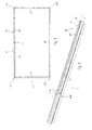
- Fig. 1 a sketch of the embodiment of a frame element 2 according to the invention is shown.
- the frame member 2 is formed to form a frame of a lamp 10.
- the luminaire 10 may in particular be a signage luminaire.
- the frame element 2 is sketched in a frame state in which it can serve as a frame of the luminaire 10.
- the frame element 2 is sketched in a side view in a linear state in which it extends along a longitudinal axis L. Accordingly, the frame member 2 has a first end portion 21 and a second end portion 22 with respect to the longitudinal axis L.
- the design is preferably such that in the frame state between the first end portion 21 and the second end portion 22 a joint 7 is formed. This makes it possible to form a quasi-annular closed frame.
- the distance between the first end region 21 and the second end region 22 is preferably less than 2 mm, particularly preferably less than 1 mm.
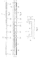
- Fig. 4 shows a corresponding top view of the frame member 2 and Fig. 2 shows a perspective sketch around the second end portion 22 of the frame member 2 in the linear state.
- the frame element 2 has folding points or predetermined bending points 3 and is designed such that it can be deformed or bent from the linear state by bending the predetermined bending points 3 into the frame state. In this way, a frame can be formed for the luminaire 10 without the need for corner connectors.
- the frame member 2 is made of aluminum. In terms of manufacturing technology, it is formed from a U-shaped profile part, in particular from an extruded profile part.
- Fig. 5 is a corresponding cross-section normal to the longitudinal axis L sketched, which reveals the U-shape of the profile part. Due to the U-shape, two U-legs 24, 25 and one, the two U-legs 24, 25 interconnecting connecting leg 26 are formed.
- the frame member 2 preferably has a total of exactly four predetermined bending points 31, 32, 33, 34.
- the joint 7 can be formed in this way in the case of a square frame between two adjacent corners.
- the frame element 2 forms a quadrangular frame in the frame state
- four rectilinear sections are formed in this way, through which the sides of the corresponding quadrangle are formed.
- the joint 7 is formed within the further section s4 .
- miter cuts 4 are advantageously formed at the predetermined bending points.
- the miter cuts 4 are advantageously inclined by 45 ° with respect to the longitudinal axis L.
- wedge-shaped recesses are formed by the miter cuts 4 at the predetermined bending points 3, which form an angle of 90 °.
- the miter cuts 4 can be designed such that they extend into the connecting leg 26 into it.
- the predetermined bending points 3 each have material dilutions 5, which are formed transversely, in particular at right angles to the longitudinal axis L.
- the material dilutions 5 are preferably designed in such a way that the frame element 2 hereby has a reduced thickness at the predetermined bending points 3, which is approximately between 0.01% and 0.2% of the length l of the frame element 2 in the linear state along the longitudinal axis L. , Vorzugswise the material dilutions 5 are formed by the miter cuts 4.
- the length l may be between 500 mm and 1500 mm and the thickness at the predetermined bending points 3 between 0.4 mm and 1.0 mm, preferably between 0.5 mm and 0.9 mm, for example 0.7 mm.
- the distance between the two end regions 21, 22 in the frame state is preferably less than 0.1% of the length l .
- the frame element 2 may have a - in Fig. 5 designated - width b parallel to the predetermined bending points 3 and a height h perpendicular to the longitudinal axis L and the width b preferably, wherein the width b is between 1% and 3% of the length l and the height h is preferably between 0.2% and 1.0% of the length l.
- the width b may be between 5 mm and 50 mm, preferably between 10 mm and 25 mm, the height h between 2 mm and 10 mm, preferably between 3 mm and 8 mm.
- the miter cuts 4 and / or the material dilutions 5 can be formed in particular by milling.
- the frame element 2 further preferably has latching elements 6.
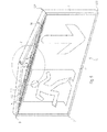
- the lamp 10 preferably has a plate-shaped light-emitting element 11 in a first approximation, the frame element 2 being arranged in the frame state around the light-emitting element 11 in the form of a frame.
- Fig. 9 shows a corresponding front view.
- the light-emitting element 11 can have one or more pictograms, in particular on two opposite outer surfaces separated from one another by the frame element 2.
- the light-emitting element 11 is made of plastic;
- it is formed from two plastic shells 111, 112.
- the design is preferably such that the parting line formed between the plastic shells 111, 112 is covered by the frame member 2, when the frame member 2 is arranged around the light emitting element 11 as intended in the frame state.
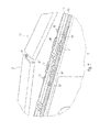
- the light emitting element 11 has latching elements 9, for a latching connection with the locking elements 6 of the frame member 2 for fixing the frame member 2 in the frame state are formed.
- This latching connection is preferably designed such that the frame element 2 is secured both against unfolding from the frame state
- the latching connection can be configured such that the frame member 2 is held under train in the frame state.
- this includes the locking elements 9 of the light emitting element 11 a - Fig. 7 exemplified - in particular elastically ausbiegbares snap element 91, which interacts with a locking lug 61 formed by the locking elements 6 of the frame member 2, so that the frame member 2 is secured against loosening of the light emitting element 11, ie against unfolding from the frame state.
- each at least one such latching lug 61, 61 'and the locking elements 9 of the light emitting element 11 can accordingly - as exemplified Fig. 7 seen - at least two snap elements 91, 91 ', so that in each case one of the latching lugs 61, 61' interacts with one of the snap elements 91, 91 'for producing the latching connection.
- Fig. 7 seen - at least two snap elements 91, 91 '
- the locking elements 9 of the light-emitting element 11 comprise a clamping nub 92, which with a formed by the locking elements 6 of the frame element 2 - Fig. 8 as shown by way of example - recess 62 interacts to produce the latching connection, so that the frame element 2 is secured against moving apart of the two end regions 21, 22, ie against opening of the joint 7.
- the clamping knob 92 engages in the recess 62.
- At least one corresponding recess 62, 62 ' is formed on each of the two end regions 21, 22 and the latching elements 9 of the light-emitting element 11 comprise at least two clamping knobs 92, 92', which are connected to the are formed counterpart concerned.
- two respective recesses 62, 62 ' are formed on each of the two end regions 21, 22 of the frame element 2, and correspondingly four corresponding clamping knobs 92, 92' on the light emission element 11.
- the design of the clamping knobs 92, 92 'and the recess 62, 62' is preferably such that thereby the frame member 2 is under train in the frame state.
- the configuration of the latching elements 6 of the frame element 2 and the latching elements 9 of the light-emitting element 11 can also be selected so that the snap-action elements 91, 91 'and / or the clamping knobs 92, 92' are not formed on the light-emitting element 11 but on the frame element 2 and the corresponding, thus interacting latching elements on the light-emitting element 11.
- the embodiment described first is advantageous in terms of manufacturing technology.
- the recess 62 or the recesses 62, 62 ' can be comparatively easily formed by milling.
- the locking elements 6 are preferably formed on the two U-legs 24, 25 of the frame member 2, which are given by the U-shape of the profile part.
- the frame element 2 can be formed particularly simply with a comparatively small height h , so that the frame formed by the frame element 2 appears or is particularly narrow.
- the locking elements 6 of the frame member 2 are preferably designed such that they extend from the two opposite U-legs 24, 25 of the frame member 2 with respect to the U-shape inwardly. As a result, a particularly even external appearance of the frame is still possible.
- the locking elements 9 of the light-emitting element 11 are preferably designed such that they are within the U-shape when the frame element 2 as intended is around the light-emitting element 11 in the frame state.
- the light-emitting element 11 consists of two plastic shells 111, 112
- the latter can each have at their edge regions along the parting line a preferably circumferential flange-like projection, which is in each case within the U-shape, when the frame element 2 as provided in the frame state around the Light emitting element 11 is arranged around. In this way, a cohesion of the two plastic shells 111, 112 cause or support by the U-shape.
- the latching connection is further preferably designed such that it can be reversibly loosened and restored.
- the predetermined bending points 3 are preferably designed for repeated bends.
- the frame element 2 can be separated from the light-emitting element 11 and fastened to it again. This may be desirable, for example, for maintenance work in an interior of the light-emitting element 11.
- the locking lugs 61, 61 'of the corresponding snap elements 91, 91' are released by levers.
- the frame member 2 further comprises at least one opening 14, for example two openings 14, which is or are for mounting a suspension means of the lamp, for example in the form of at least one cable or at least one pendulum rod.
- the frame member 2 is not only suitable in the case of a escape sign lamp. It can also be used for example to include outlet openings of larger lights.
- the frame element 2 can be produced in a particularly simple manner from an aluminum extruded profile.
- the post-processing of the corresponding profile part for the production of the predetermined bending points 3 and the locking elements 6 of the frame member 2 requires only relatively little effort.
- the attachment of the frame member 2 to the light-emitting element 11 is particularly simple and fast.
Landscapes
- Physics & Mathematics (AREA)
- General Physics & Mathematics (AREA)
- Engineering & Computer Science (AREA)
- Theoretical Computer Science (AREA)
- Business, Economics & Management (AREA)
- Emergency Management (AREA)
- Non-Portable Lighting Devices Or Systems Thereof (AREA)
- Fastening Of Light Sources Or Lamp Holders (AREA)
Applications Claiming Priority (1)
| Application Number | Priority Date | Filing Date | Title |
|---|---|---|---|
| DE102012200972A DE102012200972A1 (de) | 2012-01-24 | 2012-01-24 | Rahmenelement für eine Leuchte |
Publications (3)
| Publication Number | Publication Date |
|---|---|
| EP2620936A2 true EP2620936A2 (fr) | 2013-07-31 |
| EP2620936A3 EP2620936A3 (fr) | 2014-10-01 |
| EP2620936B1 EP2620936B1 (fr) | 2018-03-28 |
Family
ID=47665933
Family Applications (1)
| Application Number | Title | Priority Date | Filing Date |
|---|---|---|---|
| EP13152171.8A Not-in-force EP2620936B1 (fr) | 2012-01-24 | 2013-01-22 | Lampe avec élément d'encadrement |
Country Status (2)
| Country | Link |
|---|---|
| EP (1) | EP2620936B1 (fr) |
| DE (1) | DE102012200972A1 (fr) |
Families Citing this family (2)
| Publication number | Priority date | Publication date | Assignee | Title |
|---|---|---|---|---|
| DE102013215290B4 (de) * | 2013-08-02 | 2020-06-18 | Trilux Gmbh & Co. Kg | Montagekörper für eine Leuchte |
| CN104289594B (zh) * | 2014-10-14 | 2016-06-08 | 江苏省南扬机械制造有限公司 | 一种t形灯具型材的生产装置及生产方法 |
Family Cites Families (9)
| Publication number | Priority date | Publication date | Assignee | Title |
|---|---|---|---|---|
| US3396483A (en) * | 1965-04-23 | 1968-08-13 | Stein | Sign frame |
| DE1242726B (de) * | 1965-11-26 | 1967-06-22 | Telefunken Patent | Chassis fuer ein Geraet der Elektrotechnik aus einer gedruckten Leiterplatte und einem rahmenfoermigen Traeger |
| DE2461329A1 (de) * | 1974-12-24 | 1976-07-08 | Mutzhas Maximilian F | Ein- oder mehrseitig leuchtende lichtwerbeanlagen |
| GB1558844A (en) * | 1977-02-21 | 1980-01-09 | Mcneil J C | Lightbox |
| DE3246459A1 (de) * | 1982-12-15 | 1983-07-28 | Erich 6483 Bad Soden-Salmünster Löhnert | Winkelverbindung fuer faltrahmenteile in hohlkoerperausfuehrung |
| DE29520605U1 (de) * | 1995-12-28 | 1996-02-15 | Siebert, Max, 76761 Rülzheim | Beleuchtungsvorrichtung wie Notleuchte, Hinweisleuchte o.dgl. |
| DE202004020065U1 (de) * | 2004-12-28 | 2005-04-07 | U F E Solar Vertriebsgmbh | Solarkollektor |
| DE202005002539U1 (de) * | 2005-02-17 | 2005-05-04 | Behse, Matthias | LED-Bilderrahmenbeleuchtung |
| DE202006014352U1 (de) * | 2006-04-13 | 2007-01-11 | Zumtobel Lighting Gmbh | Leuchte mit wenigstens einer lichtdurchlässigen Abdeckung |
-
2012
- 2012-01-24 DE DE102012200972A patent/DE102012200972A1/de not_active Withdrawn
-
2013
- 2013-01-22 EP EP13152171.8A patent/EP2620936B1/fr not_active Not-in-force
Also Published As
| Publication number | Publication date |
|---|---|
| DE102012200972A1 (de) | 2013-07-25 |
| EP2620936B1 (fr) | 2018-03-28 |
| EP2620936A3 (fr) | 2014-10-01 |
Similar Documents
| Publication | Publication Date | Title |
|---|---|---|
| DE102017121597A1 (de) | Schubkasten | |
| DE202014104866U1 (de) | Knotenverbindung für Verbindungsholme und zugehöriges modular aufgebautes Tischgestell | |
| EP3614885A1 (fr) | Structure de cadre pour système d'étagères | |
| EP1441081B1 (fr) | Connecteur pour profilés et ensemble de connexion | |
| DE4006213C2 (fr) | ||
| DE102019109676A1 (de) | Haltefeder für Leuchte | |
| EP2657595B1 (fr) | Raccord d'angle pour un cadre d'un éclairage, cadre et éclairage | |
| DE10120738C1 (de) | Profilstahlgerüst aus verschraubten Profilstücken | |
| EP2620936B1 (fr) | Lampe avec élément d'encadrement | |
| EP3608588B1 (fr) | Ressort de maintien pour luminaire | |
| DE202008004786U1 (de) | Modulares Lichtband | |
| DE202013103254U1 (de) | Verbindung zwischen Profilelementen einer Rahmenkonstruktion | |
| DE10147925A1 (de) | Sockel für einen Schaltschrank | |
| DE102012012043B4 (de) | Bespannte Rahmenkonstruktion und Kulisse mit einer solchen Rahmenkonstruktion | |
| AT394617B (de) | Fenstersprossensystem aus hohlprofilen und deren verbindungen | |
| DE102016123321B4 (de) | Rollladenkasten | |
| DE8202245U1 (de) | Rahmenkonstruktion, insbesondere fuer moebel | |
| DE102009003910A1 (de) | Tragschiene für eine Vorrichtung zur Halterung von Wandplatten an einer Wand sowie Fassadenbekleidung | |
| DE102011081744A1 (de) | Lichtleitkörper und lichtdurchlässiger Verbundkörper sowie Verfahren zu deren Herstellung | |
| DE102011106400A1 (de) | Bauteil aus mindestens zwei Profilelementen | |
| DE102022120909A1 (de) | Bilderrahmen | |
| DE102017111978A1 (de) | Haltefeder | |
| AT500414A1 (de) | Friedhofslaterne | |
| EP2912651B1 (fr) | Élément émetteur de lumière pour une lampe ainsi que lampe pourvue d'un élément émetteur de lumière | |
| DE3302820A1 (de) | Wechselrahmen |
Legal Events
| Date | Code | Title | Description |
|---|---|---|---|
| PUAI | Public reference made under article 153(3) epc to a published international application that has entered the european phase |
Free format text: ORIGINAL CODE: 0009012 |
|
| AK | Designated contracting states |
Kind code of ref document: A2 Designated state(s): AL AT BE BG CH CY CZ DE DK EE ES FI FR GB GR HR HU IE IS IT LI LT LU LV MC MK MT NL NO PL PT RO RS SE SI SK SM TR |
|
| AX | Request for extension of the european patent |
Extension state: BA ME |
|
| PUAL | Search report despatched |
Free format text: ORIGINAL CODE: 0009013 |
|
| AK | Designated contracting states |
Kind code of ref document: A3 Designated state(s): AL AT BE BG CH CY CZ DE DK EE ES FI FR GB GR HR HU IE IS IT LI LT LU LV MC MK MT NL NO PL PT RO RS SE SI SK SM TR |
|
| AX | Request for extension of the european patent |
Extension state: BA ME |
|
| RIC1 | Information provided on ipc code assigned before grant |
Ipc: G09F 13/18 20060101ALN20140828BHEP Ipc: G09F 13/04 20060101AFI20140828BHEP Ipc: G09F 13/22 20060101ALN20140828BHEP |
|
| 17P | Request for examination filed |
Effective date: 20150225 |
|
| RBV | Designated contracting states (corrected) |
Designated state(s): AL AT BE BG CH CY CZ DE DK EE ES FI FR GB GR HR HU IE IS IT LI LT LU LV MC MK MT NL NO PL PT RO RS SE SI SK SM TR |
|
| STAA | Information on the status of an ep patent application or granted ep patent |
Free format text: STATUS: EXAMINATION IS IN PROGRESS |
|
| 17Q | First examination report despatched |
Effective date: 20170609 |
|
| GRAP | Despatch of communication of intention to grant a patent |
Free format text: ORIGINAL CODE: EPIDOSNIGR1 |
|
| STAA | Information on the status of an ep patent application or granted ep patent |
Free format text: STATUS: GRANT OF PATENT IS INTENDED |
|
| RIC1 | Information provided on ipc code assigned before grant |
Ipc: G09F 13/22 20060101ALN20171128BHEP Ipc: G09F 13/04 20060101AFI20171128BHEP Ipc: G09F 13/18 20060101ALN20171128BHEP |
|
| INTG | Intention to grant announced |
Effective date: 20180102 |
|
| GRAS | Grant fee paid |
Free format text: ORIGINAL CODE: EPIDOSNIGR3 |
|
| GRAA | (expected) grant |
Free format text: ORIGINAL CODE: 0009210 |
|
| STAA | Information on the status of an ep patent application or granted ep patent |
Free format text: STATUS: THE PATENT HAS BEEN GRANTED |
|
| AK | Designated contracting states |
Kind code of ref document: B1 Designated state(s): AL AT BE BG CH CY CZ DE DK EE ES FI FR GB GR HR HU IE IS IT LI LT LU LV MC MK MT NL NO PL PT RO RS SE SI SK SM TR |
|
| REG | Reference to a national code |
Ref country code: GB Ref legal event code: FG4D Free format text: NOT ENGLISH |
|
| REG | Reference to a national code |
Ref country code: CH Ref legal event code: EP |
|
| REG | Reference to a national code |
Ref country code: CH Ref legal event code: NV Representative=s name: FELBER UND PARTNER AG, CH |
|
| REG | Reference to a national code |
Ref country code: AT Ref legal event code: REF Ref document number: 984088 Country of ref document: AT Kind code of ref document: T Effective date: 20180415 |
|
| REG | Reference to a national code |
Ref country code: IE Ref legal event code: FG4D Free format text: LANGUAGE OF EP DOCUMENT: GERMAN |
|
| REG | Reference to a national code |
Ref country code: DE Ref legal event code: R096 Ref document number: 502013009752 Country of ref document: DE |
|
| PG25 | Lapsed in a contracting state [announced via postgrant information from national office to epo] |
Ref country code: FI Free format text: LAPSE BECAUSE OF FAILURE TO SUBMIT A TRANSLATION OF THE DESCRIPTION OR TO PAY THE FEE WITHIN THE PRESCRIBED TIME-LIMIT Effective date: 20180328 Ref country code: NO Free format text: LAPSE BECAUSE OF FAILURE TO SUBMIT A TRANSLATION OF THE DESCRIPTION OR TO PAY THE FEE WITHIN THE PRESCRIBED TIME-LIMIT Effective date: 20180628 Ref country code: HR Free format text: LAPSE BECAUSE OF FAILURE TO SUBMIT A TRANSLATION OF THE DESCRIPTION OR TO PAY THE FEE WITHIN THE PRESCRIBED TIME-LIMIT Effective date: 20180328 Ref country code: LT Free format text: LAPSE BECAUSE OF FAILURE TO SUBMIT A TRANSLATION OF THE DESCRIPTION OR TO PAY THE FEE WITHIN THE PRESCRIBED TIME-LIMIT Effective date: 20180328 |
|
| REG | Reference to a national code |
Ref country code: NL Ref legal event code: MP Effective date: 20180328 |
|
| REG | Reference to a national code |
Ref country code: LT Ref legal event code: MG4D |
|
| PG25 | Lapsed in a contracting state [announced via postgrant information from national office to epo] |
Ref country code: GR Free format text: LAPSE BECAUSE OF FAILURE TO SUBMIT A TRANSLATION OF THE DESCRIPTION OR TO PAY THE FEE WITHIN THE PRESCRIBED TIME-LIMIT Effective date: 20180629 Ref country code: SE Free format text: LAPSE BECAUSE OF FAILURE TO SUBMIT A TRANSLATION OF THE DESCRIPTION OR TO PAY THE FEE WITHIN THE PRESCRIBED TIME-LIMIT Effective date: 20180328 Ref country code: LV Free format text: LAPSE BECAUSE OF FAILURE TO SUBMIT A TRANSLATION OF THE DESCRIPTION OR TO PAY THE FEE WITHIN THE PRESCRIBED TIME-LIMIT Effective date: 20180328 Ref country code: BG Free format text: LAPSE BECAUSE OF FAILURE TO SUBMIT A TRANSLATION OF THE DESCRIPTION OR TO PAY THE FEE WITHIN THE PRESCRIBED TIME-LIMIT Effective date: 20180628 Ref country code: RS Free format text: LAPSE BECAUSE OF FAILURE TO SUBMIT A TRANSLATION OF THE DESCRIPTION OR TO PAY THE FEE WITHIN THE PRESCRIBED TIME-LIMIT Effective date: 20180328 |
|
| PG25 | Lapsed in a contracting state [announced via postgrant information from national office to epo] |
Ref country code: MT Free format text: LAPSE BECAUSE OF FAILURE TO SUBMIT A TRANSLATION OF THE DESCRIPTION OR TO PAY THE FEE WITHIN THE PRESCRIBED TIME-LIMIT Effective date: 20180328 |
|
| PG25 | Lapsed in a contracting state [announced via postgrant information from national office to epo] |
Ref country code: PL Free format text: LAPSE BECAUSE OF FAILURE TO SUBMIT A TRANSLATION OF THE DESCRIPTION OR TO PAY THE FEE WITHIN THE PRESCRIBED TIME-LIMIT Effective date: 20180328 Ref country code: NL Free format text: LAPSE BECAUSE OF FAILURE TO SUBMIT A TRANSLATION OF THE DESCRIPTION OR TO PAY THE FEE WITHIN THE PRESCRIBED TIME-LIMIT Effective date: 20180328 Ref country code: AL Free format text: LAPSE BECAUSE OF FAILURE TO SUBMIT A TRANSLATION OF THE DESCRIPTION OR TO PAY THE FEE WITHIN THE PRESCRIBED TIME-LIMIT Effective date: 20180328 Ref country code: ES Free format text: LAPSE BECAUSE OF FAILURE TO SUBMIT A TRANSLATION OF THE DESCRIPTION OR TO PAY THE FEE WITHIN THE PRESCRIBED TIME-LIMIT Effective date: 20180328 Ref country code: EE Free format text: LAPSE BECAUSE OF FAILURE TO SUBMIT A TRANSLATION OF THE DESCRIPTION OR TO PAY THE FEE WITHIN THE PRESCRIBED TIME-LIMIT Effective date: 20180328 Ref country code: RO Free format text: LAPSE BECAUSE OF FAILURE TO SUBMIT A TRANSLATION OF THE DESCRIPTION OR TO PAY THE FEE WITHIN THE PRESCRIBED TIME-LIMIT Effective date: 20180328 |
|
| PG25 | Lapsed in a contracting state [announced via postgrant information from national office to epo] |
Ref country code: CZ Free format text: LAPSE BECAUSE OF FAILURE TO SUBMIT A TRANSLATION OF THE DESCRIPTION OR TO PAY THE FEE WITHIN THE PRESCRIBED TIME-LIMIT Effective date: 20180328 Ref country code: SM Free format text: LAPSE BECAUSE OF FAILURE TO SUBMIT A TRANSLATION OF THE DESCRIPTION OR TO PAY THE FEE WITHIN THE PRESCRIBED TIME-LIMIT Effective date: 20180328 Ref country code: SK Free format text: LAPSE BECAUSE OF FAILURE TO SUBMIT A TRANSLATION OF THE DESCRIPTION OR TO PAY THE FEE WITHIN THE PRESCRIBED TIME-LIMIT Effective date: 20180328 |
|
| PG25 | Lapsed in a contracting state [announced via postgrant information from national office to epo] |
Ref country code: PT Free format text: LAPSE BECAUSE OF FAILURE TO SUBMIT A TRANSLATION OF THE DESCRIPTION OR TO PAY THE FEE WITHIN THE PRESCRIBED TIME-LIMIT Effective date: 20180730 |
|
| REG | Reference to a national code |
Ref country code: DE Ref legal event code: R097 Ref document number: 502013009752 Country of ref document: DE |
|
| PG25 | Lapsed in a contracting state [announced via postgrant information from national office to epo] |
Ref country code: DK Free format text: LAPSE BECAUSE OF FAILURE TO SUBMIT A TRANSLATION OF THE DESCRIPTION OR TO PAY THE FEE WITHIN THE PRESCRIBED TIME-LIMIT Effective date: 20180328 |
|
| PLBE | No opposition filed within time limit |
Free format text: ORIGINAL CODE: 0009261 |
|
| STAA | Information on the status of an ep patent application or granted ep patent |
Free format text: STATUS: NO OPPOSITION FILED WITHIN TIME LIMIT |
|
| PG25 | Lapsed in a contracting state [announced via postgrant information from national office to epo] |
Ref country code: IT Free format text: LAPSE BECAUSE OF FAILURE TO SUBMIT A TRANSLATION OF THE DESCRIPTION OR TO PAY THE FEE WITHIN THE PRESCRIBED TIME-LIMIT Effective date: 20180328 |
|
| 26N | No opposition filed |
Effective date: 20190103 |
|
| PGFP | Annual fee paid to national office [announced via postgrant information from national office to epo] |
Ref country code: CH Payment date: 20190130 Year of fee payment: 7 Ref country code: FR Payment date: 20190128 Year of fee payment: 7 Ref country code: GB Payment date: 20190130 Year of fee payment: 7 |
|
| PG25 | Lapsed in a contracting state [announced via postgrant information from national office to epo] |
Ref country code: SI Free format text: LAPSE BECAUSE OF FAILURE TO SUBMIT A TRANSLATION OF THE DESCRIPTION OR TO PAY THE FEE WITHIN THE PRESCRIBED TIME-LIMIT Effective date: 20180328 |
|
| PG25 | Lapsed in a contracting state [announced via postgrant information from national office to epo] |
Ref country code: MC Free format text: LAPSE BECAUSE OF FAILURE TO SUBMIT A TRANSLATION OF THE DESCRIPTION OR TO PAY THE FEE WITHIN THE PRESCRIBED TIME-LIMIT Effective date: 20180328 |
|
| PG25 | Lapsed in a contracting state [announced via postgrant information from national office to epo] |
Ref country code: LU Free format text: LAPSE BECAUSE OF NON-PAYMENT OF DUE FEES Effective date: 20190122 |
|
| REG | Reference to a national code |
Ref country code: BE Ref legal event code: MM Effective date: 20190131 |
|
| REG | Reference to a national code |
Ref country code: DE Ref legal event code: R084 Ref document number: 502013009752 Country of ref document: DE |
|
| REG | Reference to a national code |
Ref country code: IE Ref legal event code: MM4A |
|
| PG25 | Lapsed in a contracting state [announced via postgrant information from national office to epo] |
Ref country code: BE Free format text: LAPSE BECAUSE OF NON-PAYMENT OF DUE FEES Effective date: 20190131 |
|
| PG25 | Lapsed in a contracting state [announced via postgrant information from national office to epo] |
Ref country code: IE Free format text: LAPSE BECAUSE OF NON-PAYMENT OF DUE FEES Effective date: 20190122 |
|
| REG | Reference to a national code |
Ref country code: AT Ref legal event code: MM01 Ref document number: 984088 Country of ref document: AT Kind code of ref document: T Effective date: 20190122 |
|
| PG25 | Lapsed in a contracting state [announced via postgrant information from national office to epo] |
Ref country code: TR Free format text: LAPSE BECAUSE OF FAILURE TO SUBMIT A TRANSLATION OF THE DESCRIPTION OR TO PAY THE FEE WITHIN THE PRESCRIBED TIME-LIMIT Effective date: 20180328 |
|
| PG25 | Lapsed in a contracting state [announced via postgrant information from national office to epo] |
Ref country code: AT Free format text: LAPSE BECAUSE OF NON-PAYMENT OF DUE FEES Effective date: 20190122 |
|
| REG | Reference to a national code |
Ref country code: CH Ref legal event code: PL |
|
| GBPC | Gb: european patent ceased through non-payment of renewal fee |
Effective date: 20200122 |
|
| PG25 | Lapsed in a contracting state [announced via postgrant information from national office to epo] |
Ref country code: GB Free format text: LAPSE BECAUSE OF NON-PAYMENT OF DUE FEES Effective date: 20200122 Ref country code: FR Free format text: LAPSE BECAUSE OF NON-PAYMENT OF DUE FEES Effective date: 20200131 |
|
| PG25 | Lapsed in a contracting state [announced via postgrant information from national office to epo] |
Ref country code: LI Free format text: LAPSE BECAUSE OF NON-PAYMENT OF DUE FEES Effective date: 20200131 Ref country code: CH Free format text: LAPSE BECAUSE OF NON-PAYMENT OF DUE FEES Effective date: 20200131 |
|
| PG25 | Lapsed in a contracting state [announced via postgrant information from national office to epo] |
Ref country code: CY Free format text: LAPSE BECAUSE OF FAILURE TO SUBMIT A TRANSLATION OF THE DESCRIPTION OR TO PAY THE FEE WITHIN THE PRESCRIBED TIME-LIMIT Effective date: 20180328 |
|
| PG25 | Lapsed in a contracting state [announced via postgrant information from national office to epo] |
Ref country code: IS Free format text: LAPSE BECAUSE OF FAILURE TO SUBMIT A TRANSLATION OF THE DESCRIPTION OR TO PAY THE FEE WITHIN THE PRESCRIBED TIME-LIMIT Effective date: 20180728 |
|
| PG25 | Lapsed in a contracting state [announced via postgrant information from national office to epo] |
Ref country code: HU Free format text: LAPSE BECAUSE OF FAILURE TO SUBMIT A TRANSLATION OF THE DESCRIPTION OR TO PAY THE FEE WITHIN THE PRESCRIBED TIME-LIMIT; INVALID AB INITIO Effective date: 20130122 |
|
| PG25 | Lapsed in a contracting state [announced via postgrant information from national office to epo] |
Ref country code: MK Free format text: LAPSE BECAUSE OF FAILURE TO SUBMIT A TRANSLATION OF THE DESCRIPTION OR TO PAY THE FEE WITHIN THE PRESCRIBED TIME-LIMIT Effective date: 20180328 |
|
| PGFP | Annual fee paid to national office [announced via postgrant information from national office to epo] |
Ref country code: DE Payment date: 20230127 Year of fee payment: 11 |
|
| P01 | Opt-out of the competence of the unified patent court (upc) registered |
Effective date: 20230530 |
|
| REG | Reference to a national code |
Ref country code: DE Ref legal event code: R119 Ref document number: 502013009752 Country of ref document: DE |
|
| PG25 | Lapsed in a contracting state [announced via postgrant information from national office to epo] |
Ref country code: DE Free format text: LAPSE BECAUSE OF NON-PAYMENT OF DUE FEES Effective date: 20240801 |
|
| PG25 | Lapsed in a contracting state [announced via postgrant information from national office to epo] |
Ref country code: DE Free format text: LAPSE BECAUSE OF NON-PAYMENT OF DUE FEES Effective date: 20240801 |