EP2621040B1 - Dispositif de commutation isolé par un gaz - Google Patents
Dispositif de commutation isolé par un gaz Download PDFInfo
- Publication number
- EP2621040B1 EP2621040B1 EP10857553.1A EP10857553A EP2621040B1 EP 2621040 B1 EP2621040 B1 EP 2621040B1 EP 10857553 A EP10857553 A EP 10857553A EP 2621040 B1 EP2621040 B1 EP 2621040B1
- Authority
- EP
- European Patent Office
- Prior art keywords
- circuit breaker
- bus bar
- phase
- disconnect switch
- gas
- Prior art date
- Legal status (The legal status is an assumption and is not a legal conclusion. Google has not performed a legal analysis and makes no representation as to the accuracy of the status listed.)
- Active
Links
Images





Classifications
-
- H—ELECTRICITY
- H02—GENERATION; CONVERSION OR DISTRIBUTION OF ELECTRIC POWER
- H02B—BOARDS, SUBSTATIONS OR SWITCHING ARRANGEMENTS FOR THE SUPPLY OR DISTRIBUTION OF ELECTRIC POWER
- H02B13/00—Arrangement of switchgear in which switches are enclosed in, or structurally associated with, a casing, e.g. cubicle
-
- H—ELECTRICITY
- H02—GENERATION; CONVERSION OR DISTRIBUTION OF ELECTRIC POWER
- H02B—BOARDS, SUBSTATIONS OR SWITCHING ARRANGEMENTS FOR THE SUPPLY OR DISTRIBUTION OF ELECTRIC POWER
- H02B5/00—Non-enclosed substations; Substations with enclosed and non-enclosed equipment
- H02B5/06—Non-enclosed substations; Substations with enclosed and non-enclosed equipment gas-insulated
Definitions
- the present invention relates to a gas-insulated switchgear.
- a gas-insulated switchgear is configured to arrange required devices such as a circuit breaker within a metal container sealed and filled with insulating gas such as SF 6 (sulfur hexafluoride) gas. Whether the gas-insulated switchgear is installed indoors or outdoors, strong demand rises for a reduction in the installation area of the gas-insulated switchgear and it is a great challenge to address the problem of the installation of the gas-insulated switchgear while improving storage efficiency in a limited space.
- SF 6 sulfur hexafluoride
- Patent Literature 1 describes a configuration of a gas-insulated switchgear including: a circuit breaker that has two branch outlets facing upward on a side surface thereof and that is arranged with the longitudinal direction set horizontally; a bus-bar-side device that is connected to one of the branch outlets of the circuit breaker; and a line-side device that is connected to the other branch outlet of the circuit breaker, wherein a bus bar included in the bus-bar-side device extends in a direction orthogonal to the longitudinal direction of the circuit breaker above the circuit breaker and between the two branch outlets.
- Patent literature 2 discloses a switchgear having an horizontal circuit breaker, two flanges, disconnecting switches and bus bars connected to its flanges.
- Patent Literature 1 Japanese Patent Application Laid-open No. 2008-245376
- Patent Literature 2 JP 621 04 408 .
- the gas-insulated switchgear described in Patent Literature 1 has the following problems. Because of the arrangement of the bus bar between the two branch outlets, the circuit breaker becomes longer in the longitudinal direction by the width of a bus bar tank. As a result, there is also a problem that the installation area of the gas-insulated switchgear disadvantageously becomes larger.
- the present invention has been made to solve the above problems, and an object of the present invention is to provide a gas-insulated switchgear capable of realizing a reduction of an installation area.
- a gas-insulated switchgear includes: a circuit breaker that includes first and second branch outlets provided on a side surface of a cylindrical circuit breaker tank, the branch outlets being arranged to be distant from each other in a longitudinal direction of the circuit breaker tank and both branching off to upward; a connection bus bar that has one end connected to the first branch outlet and that extends upward; a first disconnect switch that is connected to the other end of the connection bus bar and that is arranged coaxially with the first branch outlet; a second disconnect switch that is connected to the second branch outlet, that is arranged coaxially with the second branch outlet, and that is arranged at a lower position than a position of the first disconnect switch; a line bus bar that is led out from the second disconnect switch in a horizontal direction; a main bus bar that is arranged above the second disconnect switch coaxially with the second branch outlet, that is connected to the first disconnect switch, and that extends in the horizontal direction orthogonal to the longitudinal direction of the circuit
- the installation area can be reduced.
- the abutment has a simple structure and is easy to attach.
- FIG. 1 depicts a configuration of a gas-insulated switchgear according to a first embodiment of the present invention.
- a circuit breaker 1 is what is called a horizontal circuit breaker, arranged with a longitudinal direction thereof set horizontally, and supported by an abutment 30 provided on an installation surface 40.
- a pair of branch outlets 2a and 2b arranged at a predetermined interval in the longitudinal direction and both facing upward are provided on a side surface of a circuit breaker tank of the circuit breaker 1.
- the branch outlets 2a and 2b are provided at an equal distance from a longitudinal center of the circuit breaker tank.
- the circuit breaker tank which is a cylindrical metal container, is grounded and has a circuit break unit (not shown) accommodated therein.
- the gas-insulated switchgear according to the first embodiment is applicable to both a three-phase collective type and a phase separation type.
- An operation device 3 for the circuit breaker 1 is provided side by side with the circuit breaker 1 on one longitudinal end, or specifically, on an end thereof near the branch outlet 2b.
- the operation device 3 is configured to store an operation unit (not shown) within a box constituting an outer frame, and a door 45 is provided on this box on a side in the longitudinal direction of the circuit breaker 1 and is opened or closed by operating an opening/closing lever 46, for example.
- the door 45 of the operation device 3 is in a closed state.
- a longitudinal length of the circuit breaker 1 including the operation device 3 is larger than that shown in the example of FIG. 1 . That is, in a state where the door 45 is fully open, the longitudinal length of the circuit breaker 1 including the operation device 3 is A.
- a door-open-state end 25 indicates a position of an end of the door 45 in the state where the door 45 is fully open.
- An instrument current transformer 4a is connected to the branch outlet 2a.
- the instrument current transformer 4a is arranged on a top portion of the circuit breaker 1.
- the instrument current transformer 4a measures a current carried across a central conductor (not shown) that is an energized unit connected to the circuit break unit of the circuit breaker 1.
- a cylindrical connection bus bar 6 extending upward is connected to the instrument current transformer 4a.
- a disconnect switch 5a is connected to the connection bus bar 6. That is, one end of the connection bus bar 6 is connected to the instrument current transformer 4a and the other end thereof is connected to the disconnect switch 5a.
- the instrument current transformer 4a, the connection bus bar 6, and the disconnect switch 5a are arranged coaxially with the branch outlet 2a and above the circuit breaker 1.
- a disconnect switch with an earth switch may be used as the disconnect switch 5a.
- the earth switch may be provided separately from the disconnect switch 5a.
- a main bus bar 7 is connected to the disconnect switch 5a.
- An instrument current transformer 4b is connected to the branch outlet 2b.
- the instrument current transformer 4b is arranged on a top portion of the circuit breaker 1.
- the instrument current transformer 4b measures a current that flows in a central conductor (not shown) that is an energized unit connected to the circuit break unit of the circuit breaker 1. While the instrument current transformers 4a and 4b are attached to the branch outlets 2a and 2b, respectively, in FIG. 1 , the instrument current transformers 4a and 4b may be attached to only one of the branch outlets 2a and 2b, for example.
- a disconnect switch 5b is connected to the instrument current transformer 4b.
- An arrangement height of the disconnect switch 5b is lower than that of the disconnect switch 5a by a length of the connection bus bar 6.
- a disconnect switch with an earth switch may be used as the disconnect switch 5b, for example. Alternatively, the earth switch may be provided separately from the disconnect switch 5b.
- a line bus bar 10 is connected to the disconnect switch 5b, and is led out, for example, in the same direction as the longitudinal direction of the circuit breaker 1 and to a side on which the operation device 3 is arranged.
- a cable head or an air bushing (not shown) is connected to the line bus bar 10.
- An abutment 8 is fixed to a top portion of the disconnect switch 5b.
- This abutment 8 supports the main bus bar 7 arranged above the disconnect switch 5b from below.
- the main bus bar 7 is arranged coaxially with the branch outlet 2b.
- the main bus bar 7 is arranged at the same height as that of the disconnect switch 5a, for example. This configuration is preferable because a distance between the main bus bar 7 and the disconnect switch 5a is the shortest. Nevertheless, the main bus bar 7 may be arranged at a different height from that of the disconnect switch 5a.
- the main bus bar 7 extends in a direction orthogonal to the longitudinal direction of the circuit breaker 1.
- the abutment 8 is configured to include a support 8a that directly supports the main bus bar 7 and a leg 8b connected to this support 8a.
- the main bus bar 7 is supported by the support 8a of the abutment 8 to be movable in the extending direction of the main bus bar 7. Therefore, for example, the support 8a is U-shaped or V-shaped in a cross-section. Therefore, even if the main bus bar 7 moves in the extending direction because of vibration, contraction, or the like, a resultant stress is not applied to the abutment 8 as a heavy load.
- a fast earth switch (Fast Earth Switching) 9 is provided on a top portion of the disconnect switch 5b.
- the fast earth switch 9 forcibly extinguishes, for example, an arc current and enables fast reclosing.
- a flange 9b that is a part of the fast earth switch 9 and that is provided in a lower portion of the fast earth switch 9 is fixedly fastened to a top plate 50 of the disconnect switch 5b with a fastening member such as a bolt.
- the leg 8b of the abutment 8 is also fastened to the top plate 50 together with the flange 9b. This makes it possible to efficiently assemble the fast earth switch 9 and the abutment 8 on the disconnect switch 5b.
- the abutment 8 is easy to attach because the top plate 50 of the disconnect switch 5b is plane.
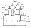
- FIG. 5 depicts a configuration of the conventional gas-insulated switchgear.
- the conventional gas-insulated switchgear is configured to include: a horizontal circuit breaker 101; an abutment 130 installed on an installation surface 140 and supporting the circuit breaker 101; a pair of branch outlets 102a and 102b provided on a side surface of a circuit breaker tank of the circuit breaker 101 and both branching off to upward; an instrument current transformer 104a provided on a top portion of the branch outlet 102a; a disconnect switch 105a provided on a top portion of the instrument current transformer 104a; a main bus bar 107 connected to the disconnect switch 105a and arranged above the circuit breaker 101 and between the branch outlets 102a and 102b, an abutment 108 provided on a top portion of the circuit breaker 101, fixed between the branch outlets 102a and 102b, and supporting the main bus bar 107 from below; an instrument current transformer 104b provided on a top portion of the branch outlet 102b; a disconnect switch 105b provided on a top portion of the instrument current transformer 104;
- the main bus bar 107 extends in a direction orthogonal to a longitudinal direction of the circuit breaker 101 between the branch outlets 102a and 102b. Therefore, a distance between the branch outlets 102a and 102b needs to be larger than at least a tank diameter of the main bus bar 107, which inevitably increases a longitudinal length of the circuit breaker 101.
- a distance between the branch outlets 2a and 2b can be made shorter than that shown in FIG. 5 by a main bus bar tank width and the longitudinal length of the circuit breaker 1 is smaller than that shown in FIG. 5 because the main bus bar 7 is arranged coaxially with the branch outlet 2b above the branch outlet 2b ( FIG. 1 ).
- FIG. 5 depicts a door 145 of the operation device 103, an opening/closing lever 146 provided on the door 145, and a door-open-state end 125.
- the door-open-state end 125 represents a farthest end of the door 145 from a center of the circuit breaker 101 in the state where the door 145 is fully open.
- the abutment 108 needs to be fixed onto the circuit breaker 101 to support the main bus bar 107.
- a separate structure for attachment is required, and it takes time and labor for the attachment.
- the abutment 8 can be efficiently attached to the disconnect switch 5b by fastening the abutment 8 together with the fast earth switch 9.
- the longitudinal length of the circuit breaker 1 can be made shorter than that of the conventional technique and an installation area of the gas-insulated switchgear can be reduced because the main bus bar 7 can be arranged above the branch outlet 2b.
- the first embodiment it is possible to simplify the structure of the abutment 8 and facilitate attachment thereof as compared with the conventional technique because it suffices to arrange the abutment 8 supporting the main bus bar 7 on the top portion of the disconnect switch 5b.
- FIG. 1 the operation device 3 is provided side by side with the circuit breaker 1 on the longitudinal end near the branch outlet 2b. This is because it facilitates disassembling of the gas-insulated switchgear.
- FIG. 2 depicts a part of a procedure of disassembling the gas-insulated switchgear according to the first embodiment. More specifically, FIG. 2 depicts a part of the procedure of disassembling the gas-insulated switchgear when the operation device 3 is provided side by side with the circuit breaker 1.
- FIG. 8 depicts a part of a procedure of disassembling a gas-insulated switchgear when an operation device 153 is placed vertically to the circuit breaker 101.
- FIG. 2 depicts the circuit breaker 1, the operation device 3, and the abutment 30 that are a part of the constituent elements shown in FIG. 1 .
- an internal component 55 arranged within the circuit breaker tank is shown in the circuit breaker 1.
- the internal component 55 represents constituent components of the circuit breaker 1 including the circuit break unit and the like.
- the operation device 3 is provided side by side with the circuit breaker 1 as in an example shown in FIG. 2
- the internal component 55 and the operation device 3 can be disassembled by integrally pulling out the internal component 55 and the operation device 3 from the circuit breaker tank after detaching the internal component 55 from the side of the disconnect switches 5a and 5b in disassembling regions 33.
- a direction of pulling out the internal component 55 and the operation device 3 is the longitudinal direction of the circuit breaker 1 (see an arrow shown in FIG. 2 ).
- FIG. 8 depicts the horizontal circuit breaker 101, the abutment 130 supporting the circuit breaker 101, and the operation device 153 provided in a lower portion of the circuit breaker 101.
- An internal component 155 arranged within the circuit breaker tank is shown in the circuit breaker 101.
- the internal component 155 represents constituent components of the circuit breaker 101 including a circuit break unit and the like.
- the operation device 153 is provided in the lower portion of the circuit breaker 101 in what is called a vertically-placed manner. In this case, the operation device 153 is detached from the internal component 155 in a disassembling region 133 first, and moved downward to disassemble the operation device 153.
- the internal component 155 is then detached from a side of disconnect switches (not shown) and pulled out from the circuit breaker tank in the longitudinal direction of the circuit breaker tank in disassembling regions 134.
- the internal component 155 can be thereby disassembled. That is, in a case of vertically placing the operation device 153, the internal component 155 and the operation device 3 are disassembled at two separate stages. Therefore, the operation device placed side by side is easier to disassemble than that placed vertically. The same holds true for the assembly workability. In FIG. 1 , the operation device 3 can be placed vertically as shown in FIG. 8 .
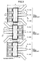
- FIG. 3 is a top view of an arrangement configuration of a gas-insulated switchgear according to a second embodiment of the present invention.
- FIG. 4(a) is a side view taken in the direction of arrows X-X in FIG. 3
- FIG. 4(b) is a side view taken in the direction of arrows Y-Y in FIG. 3 .
- the gas-insulated switchgear is configured to include three-phase units 12-1 to 12-3 provided in parallel in the extending direction of the main bus bars 7.
- the three-phase unit 12-1 is configured to provide a U-phase circuit breaker unit 13U, a V-phase circuit breaker unit 13V, and a W-phase circuit breaker unit 13W in parallel in the extending direction of the main bus bars 7.
- the V-phase circuit breaker unit 13V includes the circuit breaker 1, the operation device 3, the instrument current transformers 4a and 4b, the disconnect switches 5a and 5b, the connection bus bar 6, the main bus bar 7, the abutment 8, the fast earth switch 9, and the line bus bar 10 ( FIG. 4(a) ).
- the configuration of the V-phase circuit breaker unit 13V is the same as that shown in FIG. 1 explained in the first embodiment. However, in the circuit breaker unit 13V, a distance from either a central axis of the branch outlet 2b or a bus bar center of the main bus bar 7 to the farthest end (the door-open-state end 25) of the operation device 3 in the longitudinal direction of the circuit breaker tank is equal to a distance from either the central axis of the branch outlet 2b or the bus bar center of the main bus bar 7 to a longitudinal end of the circuit breaker tank near the branch outlet 2a, and the distances are A/2, respectively ( FIG. 4(a) ).
- the configuration of the V-phase circuit breaker unit 13V can be applicable to the configurations of the U-phase circuit breaker unit 13U and the W-phase circuit breaker unit 13W.
- the circuit breakers 1 in the respective phases of the three-phase unit 12-1 are arranged in parallel to one another and arrayed in the extending direction of the main bus bars 7. Furthermore, a bus bar tank 17 is shared among the main bus bars 7 of the respective phases of the three-phase unit 12-1, and central conductors (not shown) in the respective phases are stored within this bus bar tank 17 as a collective three-phases. Moreover, the line bus bars 10 in the respective phases of the three-phase unit 12-1 are led out in the same direction.
- the three-phase unit 12-2 is configured to provide a U-phase circuit breaker unit 14U, a V-phase circuit breaker unit 14V, and a W-phase circuit breaker unit 14W in parallel in the extending direction of the main bus bars 7.
- the V-phase circuit breaker unit 14V includes the circuit breaker 1, the operation device 3, the instrument current transformers 4a and 4b, the disconnect switches 5a and 5b, the connection bus bar 6, the main bus bar 7, the abutment 8, the fast earth switch 9, and the line bus bar 10 ( FIG. 4(b) ).
- the configuration of the V-phase circuit breaker unit 14V is the same as that shown in FIG. 1 explained in the first embodiment.
- a distance from either the central axis of the branch outlet 2b or the bus bar center of the main bus bar 7 to the farthest end (the door-open-state end 25) of the operation device 3 in the longitudinal direction of the circuit breaker tank is equal to a distance from either the central axis of the branch outlet 2b or the bus bar center of the main bus bar 7 to the longitudinal end of the circuit breaker tank near the branch outlet 2a, and the distances are A/2, respectively ( FIG. 4(b) ).
- a lead-out direction of the line bus bar 10 of the circuit breaker unit 14V is opposite to that of the line bus bars 10 of the circuit breaker units 13U, 13V, and 13W.
- the configuration of the V-phase circuit breaker unit 14V can be applicable to the configurations of the U-phase circuit breaker unit 14U and the W-phase circuit breaker unit 14W.
- the circuit breakers 1 in the respective phases of the three-phase unit 12-2 are arranged in parallel to one another and arrayed in the extending direction of the main bus bars 7. Furthermore, the bus bar tank 17 is shared among the main bus bars 7 in the respective phases of the three-phase unit 12-2, and central conductors (not shown) in the respective phases are stored within this bus bar tank 17 as a collective three-phases.
- the bus bar tank 17 of the three-phase unit 12-2 is connected to that of the three-phase unit 12-1 while matching the bus bar centers to each other, and the central conductors (not shown) in each phase are connected to one another within the bus bar tanks 17. That is, the main bus bars 7 are connected to one another for every phase among the three-phase units.
- the three-phase unit 12-3 is configured to provide a U-phase circuit breaker unit 15U, a V-phase circuit breaker unit 15V, and a W-phase circuit breaker unit 15W in parallel in the extending direction of the main bus bars 7.
- the V-phase circuit breaker unit 15V includes the circuit breaker 1, the operation device 3, the instrument current transformers 4a and 4b, the disconnect switches 5a and 5b, the connection bus bar 6, the main bus bar 7, the abutment 8, the fast earth switch 9, and the line bus bar 10.
- the configuration of the V-phase circuit breaker unit 15V is the same as that shown in FIG. 1 explained in the first embodiment.
- a distance from either the central axis of the branch outlet 2b or the bus bar center of the main bus bar 7 to the farthest end (the door-open-state end 25) of the operation device 3 in the longitudinal direction of the circuit breaker tank is equal to a distance from either the central axis of the branch outlet 2b or the bus bar center of the main bus bar 7 to the longitudinal end of the circuit breaker tank near the branch outlet 2a, and the distances are A/2, respectively.
- a lead-out direction of the line bus bar 10 of the circuit breaker unit 15V is the same as that of the line bus bars 10 of the circuit breaker units 13U, 13V, and 13W, and opposite to that of the line bus bars 10 of the circuit breaker units 14U, 14V, and 14W.
- the configuration of the V-phase circuit breaker unit 15V can be applicable to the configurations of the U-phase circuit breaker unit 15U and the W-phase circuit breaker unit 15W.
- the circuit breakers 1 in the respective phases of the three-phase unit 12-3 are arranged in parallel to one another and arrayed in the extending direction of the main bus bars 7. Furthermore, the bus bar tank 17 is shared among the main bus bars 7 in the respective phases of the three-phase unit 12-3, and central conductors (not shown) in the respective phases are stored within this bus bar tank 17 in as a collective three-phases.
- the bus bar tank 17 of the three-phase unit 12-3 is connected to that of the three-phase unit 12-2 while matching the bus bar centers to each other, and the central conductors (not shown) in each phase are connected to one another within the bus bar tanks 17. That is, the main bus bars 7 are connected to one another for every phase among the three-phase units.
- the lead-out direction of the line bus bars 10 in the three phases of the three-phase unit 12-1 is opposite to that of the line bus bars 10 in the three phases of the three-phase unit 12-2.
- the lead-out direction of the line bus bars 10 in the three phases of the three-phase unit 12-2 is opposite to that of the line bus bars 10 in the three phases of the three-phase unit 12-3.
- the three-phase units 12-1 to 12-3 of the gas-insulated switchgear are configured to be arranged in such a manner that the lead-out directions of the line bus bars 10 of the three-phase units are reversed with respect to an array direction of the three-phase units (or specifically, the extending direction of the main bus bars 7) in alternate three-phase units. Therefore, it is unnecessary to secure a distance among the three-phase units and to avoid collision of the line bus bars 10 for all the three-phase units 12-1 to 12-3 differently from a case of making the lead-out directions of the line bus bars 10 of the three-phase units 12-1 to 12-3 uniform. This can further reduce a length of each main bus bar 7 and contribute to a reduction in the installation area.
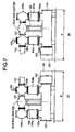
- FIG. 6 is a top view of an arrangement configuration of the gas-insulated switchgear shown in FIG. 5 in the similar layout to that shown in FIG. 3 .
- FIG. 7(a) is a side view taken in the direction of arrows X-X in FIG. 6 and
- FIG. 7(b) is a side view taken in the direction of arrows Y-Y in FIG. 6 .
- the conventional gas-insulated switchgear is configured to include three-phase units 100-1 to 100-3 provided in parallel in the extending direction of the main bus bars 107.
- the three-phase unit 100-1 is configured to provide a U-phase circuit breaker unit 113U, a V-phase circuit breaker unit 113V, and a W-phase circuit breaker unit 113W in parallel in the extending direction of the main bus bars 107.
- the V-phase circuit breaker unit 113V includes the circuit breaker 101, the operation device 103, the instrument current transformers 104a and 104b, the disconnect switches 105a and 105b, the main bus bar 107, the abutment 108, the fast earth switch 109, and the line bus bar 110 ( FIG.
- the configuration of the V-phase circuit breaker unit 113V is the same as that shown in FIG. 5 explained in the first embodiment.
- the configuration of the V-phase circuit breaker unit 113V can be applicable to the configurations of the U-phase circuit breaker unit 113U and the W-phase circuit breaker unit 113W.
- the circuit breakers 101 in the respective phases of the three-phase unit 100-1 are arranged in parallel to one another and arrayed in the extending direction of the main bus bars 107. Furthermore, a bus bar tank 117 is shared among the main bus bars 107 in the respective phases of the three-phase unit 100-1, and central conductors (not shown) in the respective phases are stored within this bus bar tank 117 as a collective three-phases. Moreover, the line bus bars 110 in the respective phases of the three-phase unit 100-1 are led out in the same direction.
- the three-phase unit 100-2 is configured to provide a U-phase circuit breaker unit 114U, a V-phase circuit breaker unit 114V, and a W-phase circuit breaker unit 114W in parallel in the extending direction of the main bus bars 107.
- the V-phase circuit breaker unit 114V includes: the circuit breaker 101; the operation device 103; the instrument current transformers 104a and 104b; the disconnect switches 105a and 105b; the main bus bar 107; the abutment 108; the fast earth switch 109; and the line bus bar 110 ( FIG. 7(b) ).
- the configuration of the V-phase circuit breaker unit 114V is the same as that shown in FIG. 5 explained in the first embodiment.
- a lead-out direction of the line bus bar 110 of the circuit breaker unit 114V is opposite to that of the line bus bars 110 of the circuit breaker units 113U, 113V, and 113W.
- the configuration of the V-phase circuit breaker unit 114V can be applicable to the configurations of the U-phase circuit breaker unit 114U and the W-phase circuit breaker unit 114W.
- the circuit breakers 101 in the respective phases of the three-phase unit 100-2 are arranged in parallel to one another and arrayed in the extending direction of the main bus bars 107. Furthermore, the bus bar tank 117 is shared among the main bus bars 107 in the respective phases of the three-phase unit 100-2, and central conductors (not shown) in the respective phases are stored within this bus bar tank 117 as a collective three-phases.
- the bus bar tank 117 of the three-phase unit 100-2 is connected to that of the three-phase unit 100-1 while matching the bus bar centers to each other, and the central conductors (not shown) in each phase are connected to one another within the bus bar tanks 117.
- the three-phase unit 100-3 is configured to provide a U-phase circuit breaker unit 115U, a V-phase circuit breaker unit 115V, and a W-phase circuit breaker unit 115W in parallel in the extending direction of the main bus bars 107.
- the V-phase circuit breaker unit 115V includes: the circuit breaker 101; the operation device 103; the instrument current transformers 104a and 104b; the disconnect switches 105a and 105b; the main bus bar 107; the abutment 108; the fast earth switch 109; and the line bus bar 110.
- the configuration of the V-phase circuit breaker unit 115V is the same as that shown in FIG. 5 explained in the first embodiment.
- a lead-out direction of the line bus bar 110 of the circuit breaker unit 115V is the same as that of the line bus bars 110 of the circuit breaker units 113U, 113V, and 113W, and opposite to that of the line bus bars 110 of the circuit breaker units 114U, 114V, and 114W.
- the configuration of the V-phase circuit breaker unit 115V can be applicable to the configurations of the U-phase circuit breaker unit 115U and the W-phase circuit breaker unit 115W.
- the circuit breakers 101 in the respective phases of the three-phase unit 100-3 are arranged in parallel to one another and arrayed in the extending direction of the main bus bars 107. Furthermore, the bus bar tank 117 is shared among the main bus bars 107 in the respective phases of the three-phase unit 100-3, and central conductors (not shown) in the respective phases are stored within this bus bar tank 117 as a collective three-phases.
- the bus bar tank 117 of the three-phase unit 100-3 is connected to that of the three-phase unit 100-2 while matching the bus bar centers to each other, and the central conductors (not shown) in each phase are connected to one another within the bus bar tanks 117.
- the three-phase units 100-1 to 100-3 are arranged in such a manner that the lead-out directions of the line bus bars 110 of the three-phase units are reversed with respect to the array direction of the three-phase units (or specifically, the extending direction of the main bus bars 107) in alternate three-phase units.
- an extension range of each of the circuit breakers 101 and the corresponding operation device 103 in the longitudinal direction of the circuit breaker 101 is (B+a), where ⁇ is a maximum length of the operation device 103 in the longitudinal direction of the circuit breaker 101.
- an extension range of each of the circuit breakers 1 and the corresponding operation device 3 in the longitudinal direction of the circuit breaker 1 is A. This is because, in FIG.
- the distance from the central axis of the branch outlet 2b to the farthest end (the door-open-state end 25) of the operation device 3 in the longitudinal direction of the circuit breaker tank is set equal to the distance from the central axis of the branch outlet 2b to the longitudinal end of the circuit breaker tank near the branch outlet 2a. Because A ⁇ B as explained in the first embodiment, A ⁇ (B+ ⁇ ) and thus a difference in lengths in the longitudinal direction of the circuit breaker 1 is far greater. In this way, the extension range of the circuit breaker 1 and the operation device 3 in the longitudinal direction of the circuit breaker 1 is shorter than that in the arrangement configuration of FIG. 6 , which contributes to the reduction in the installation area.
- the three-phase units 12-1 to 12-3 are configured to be arranged in such a manner that the lead-out directions of the line bus bars 10 of the three-phase units 12-1 to 12-3 are reversed with respect to the array direction of the three-phase units (or specifically, the extending direction of the main bus bars 7) in alternate three-phase units. Therefore, it is possible to further shorten the main bus bars 7, which contributes to the reduction in the installation area.
- the distance from either the central axis of each branch outlet 2b or the bus bar center of each main bus bar 7 to the farthest end (the door-open-state end 25) of each operation device 3 in the longitudinal direction of each circuit breaker tank is set equal to the distance from either the central axis of the branch outlet 2b or the bus bar center of the main bus bar 7 to the longitudinal end of the circuit breaker tank near each branch outlet 2a. Therefore, the extension range of the circuit breaker 1 and the operation device 3 in the longitudinal direction of the circuit breaker 1 is much shorter than that according to the conventional technique, which contributes to the reduction in the installation area.
- the number of three-phase units is assumed as three, for example.
- the number of three-phase units is not limited to three but a plurality of three-phase units can be generally provided.
- These three-phase units can be arranged in such a manner that the lead-out directions of the line bus bars 10 of the three-phase units are reversed with respect to the array direction of the three-phase units in alternate three phase units.
- the three-phase units can be configured to set the lead-out direction of the line bus bars 10 of at least one three-phase unit to be opposite to the lead-out directions of the line bus bars 10 of the remaining one or more three-phase units.
- the main bus bars 7 are shorter than those in the case where the lead-out directions of the line bus bars 10 are the same for all the three-phase units, and thus this can advantageously contribute to the reduction in the installation area.
- the three-phase units 12-1 to 12-3 can be configured to set the lead-out direction of the line bus bars 10 of the three-phase unit 12-3 to be opposite to that shown in FIG. 3 without changing the lead-out directions of the line bus bars 10 of the three-phase units 12-1 and 12-2.
- the three-phase collective type has been explained.
- the main bus bars 7 of the circuit breaker units 13U, 14U, and 15U are connected to one another
- the main bus bars 7 of the circuit breaker units 13V, 14V, and 15V are connected to one another
- the main bus bars 7 of the circuit breaker units 13W, 14W, and 15W are connected to one another.
- the main bus bars 7 are arranged at different heights among the three phases.
- the present invention is useful as a gas-insulated switchgear.
Landscapes
- Engineering & Computer Science (AREA)
- Power Engineering (AREA)
- Gas-Insulated Switchgears (AREA)
Claims (8)
- Dispositif de commutation à isolation gazeuse, comprenant :un disjoncteur (1) qui inclut des première et deuxième sorties de dérivation (2a, 2b) disposées sur une surface latérale d'un réservoir de disjoncteur cylindrique,les sorties de dérivation (2a, 2b) étant disposées pour être distantes l'une de l'autre dans une direction longitudinale du réservoir de disjoncteur et toutes deux dérivant vers le haut ;une barre bus de connexion (6) qui a une extrémité connectée à la première sortie de dérivation (2a) et qui s'étend vers le haut ;un premier commutateur de déconnexion (5a) qui est connecté à l'autre extrémité de la barre bus de connexion (6) et qui est disposé coaxialement à la première sortie de dérivation (2a) ;un deuxième commutateur de déconnexion (5b) qui est connecté à la deuxième sortie de dérivation (2b), qui est disposé coaxialement à la deuxième sortie de dérivation (2b), et qui est disposé à une position plus basse qu'une position du premier commutateur de déconnexion (5a) ;une barre bus de ligne (10) qui est sortie depuis le deuxième commutateur de déconnexion (5b) dans une direction horizontale ;une barre bus principale (7) qui est disposée au-dessus du deuxième commutateur de déconnexion (5b) coaxialement à la deuxième sortie de dérivation (2b), qui est connectée au premier commutateur de déconnexion (5a), et qui s'étend dans la direction horizontale de manière orthogonale à la direction longitudinale du réservoir de disjoncteur ; et une butée (8) qui est fixée à une partie supérieure du deuxième commutateur de déconnexion (5b) et qui soutient la barre bus principale (7) par en-dessous.
- Le dispositif de commutation à isolation gazeuse selon la revendication 1, dans lequel la barre bus principale (7) est disposée à une même hauteur qu'une hauteur du premier commutateur de déconnexion (5a).
- Le dispositif de commutation à isolation gazeuse selon la revendication 1 ou 2, dans lequel un premier transformateur de courant d'instrument est disposé entre la première sortie de dérivation (2a) et la barre bus de connexion (6), et un deuxième transformateur de courant d'instrument est disposé entre la deuxième sortie de dérivation (2b) et le deuxième commutateur de déconnexion (5b).
- Le dispositif de commutation à isolation gazeuse selon la revendication 1 ou 2, dans lequel un commutateur de terre rapide est disposé sur la partie supérieure du deuxième commutateur de déconnexion (5b), et la butée (8) conjointement avec le commutateur de terre rapide est attachée de manière fixe à la partie supérieure du deuxième commutateur de déconnexion (5b) avec un élément de fixation.
- Le dispositif de commutation à isolation gazeuse selon la revendication 1 ou 2, dans lequel un dispositif de manoeuvre pour le disjoncteur (1) est disposé côte à côte par rapport à une extrémité du disjoncteur (1) près de la deuxième sortie de dérivation (2b) dans la direction longitudinale du réservoir de disjoncteur, et la barre bus de ligne (10) est sortie dans la direction longitudinale et vers un côté duquel le dispositif de manoeuvre est disposé.
- Le dispositif de commutation à isolation gazeuse selon la revendication 1 ou 2, dans lequel une pluralité d'unités triphasées sont groupées dans une direction d'extension de la barre bus principale (7), chacune des unités triphasées incluant des unités de disjoncteur en trois phases, disposées en parallèle dans la direction d'extension de la barre bus principale (7), chacune des unités de disjoncteur incluant le disjoncteur (1), la barre bus de connexion (6), le premier commutateur de déconnexion (5a), le deuxième commutateur de déconnexion (5b), la barre bus de ligne (10), la barre bus principale (7), et la butée (8),
les barres bus principales (7) des unités triphasées sont connectées les unes aux autres pour chaque phase, et
les barres bus de ligne (10) dans les trois phases des unités triphasées sont sorties de manière opposée par rapport à la direction d'extension des barres bus principales (7) dans des unités triphasées alternées. - Le dispositif de commutation à isolation gazeuse selon la revendication 6, dans lequel une distance allant d'un axe central de chacune des deuxièmes sorties de dérivation (2b) à une extrémité la plus lointaine de chacun des dispositifs de manoeuvre dans la direction longitudinale de chacun des réservoirs de disjoncteur est égale à une distance allant de l'axe central à une extrémité du réservoir de disjoncteur correspondant situé près de chacune des premières sorties de dérivation (2a) dans la direction longitudinale.
- Le dispositif de commutation à isolation gazeuse selon la revendication 7, étant d'un type collectif triphasé.
Applications Claiming Priority (1)
| Application Number | Priority Date | Filing Date | Title |
|---|---|---|---|
| PCT/JP2010/066570 WO2012039059A1 (fr) | 2010-09-24 | 2010-09-24 | Dispositif de commutation isolé par un gaz |
Publications (3)
| Publication Number | Publication Date |
|---|---|
| EP2621040A1 EP2621040A1 (fr) | 2013-07-31 |
| EP2621040A4 EP2621040A4 (fr) | 2014-04-09 |
| EP2621040B1 true EP2621040B1 (fr) | 2015-03-25 |
Family
ID=44292647
Family Applications (1)
| Application Number | Title | Priority Date | Filing Date |
|---|---|---|---|
| EP10857553.1A Active EP2621040B1 (fr) | 2010-09-24 | 2010-09-24 | Dispositif de commutation isolé par un gaz |
Country Status (4)
| Country | Link |
|---|---|
| US (1) | US9048637B2 (fr) |
| EP (1) | EP2621040B1 (fr) |
| JP (1) | JP4712129B1 (fr) |
| WO (1) | WO2012039059A1 (fr) |
Families Citing this family (9)
| Publication number | Priority date | Publication date | Assignee | Title |
|---|---|---|---|---|
| JP5627543B2 (ja) * | 2011-07-06 | 2014-11-19 | 三菱電機株式会社 | ガス絶縁開閉装置の遮断器の取替え方法 |
| CN105119179B (zh) * | 2015-07-23 | 2017-11-03 | 平高集团有限公司 | 一种开关柜及断路器 |
| JP7146393B2 (ja) | 2017-12-28 | 2022-10-04 | 株式会社パイロットコーポレーション | 筆記具 |
| US11309693B2 (en) * | 2018-01-31 | 2022-04-19 | Mitsubishi Electric Corporation | Gas-insulated switchgear |
| EP3745547B1 (fr) * | 2019-05-31 | 2023-02-15 | Hitachi Energy Switzerland AG | Arrangement comprenant un appareil de commutation haute tension monte sur tour et une tour de transmission haute tension |
| CN115280617A (zh) * | 2020-03-24 | 2022-11-01 | 三菱电机株式会社 | 气体绝缘开闭装置 |
| WO2022085145A1 (fr) * | 2020-10-22 | 2022-04-28 | 三菱電機株式会社 | Filtre à gaz à soupape et appareillage de commutation à isolation gazeuse |
| CN115498511B (zh) * | 2021-08-10 | 2025-02-28 | 西安高压电器研究院股份有限公司 | 一种集成母线和隔离接地开关的装置以及应用设备 |
| EP4224650B1 (fr) * | 2022-02-02 | 2025-12-17 | Hitachi Energy Ltd | Module d'adaptation pour appareillage de commutation à isolation par gaz |
Family Cites Families (10)
| Publication number | Priority date | Publication date | Assignee | Title |
|---|---|---|---|---|
| DE3271824D1 (en) * | 1981-05-20 | 1986-07-31 | Hitachi Ltd | Gas insulated switchgear equipment |
| JPS6043006A (ja) | 1983-08-17 | 1985-03-07 | 株式会社東芝 | ガス絶縁開閉装置 |
| JPS62104408A (ja) * | 1985-10-28 | 1987-05-14 | 株式会社東芝 | ガス絶縁開閉装置 |
| EP1569310A1 (fr) | 2004-02-27 | 2005-08-31 | ABB Technology AG | Interrupteur blindé monophasé isolé au gas |
| JP2007295669A (ja) | 2006-04-21 | 2007-11-08 | Toshiba Corp | ガス絶縁開閉装置 |
| WO2008068944A1 (fr) * | 2006-12-05 | 2008-06-12 | Mitsubishi Electric Corporation | Appareillage de commutation étanche aux gaz |
| WO2008075436A1 (fr) * | 2006-12-21 | 2008-06-26 | Mitsubishi Electric Corporation | Appareillage de commutation à isolation gazeuse |
| JP4896786B2 (ja) | 2007-03-26 | 2012-03-14 | 三菱電機株式会社 | ガス絶縁開閉装置 |
| WO2009057218A1 (fr) * | 2007-11-01 | 2009-05-07 | Mitsubishi Electric Corporation | Appareillage de commutation à isolation gazeuse |
| US8254088B2 (en) * | 2007-12-28 | 2012-08-28 | Mitsubishi Electric Corporation | Gas-insulated switchgear |
-
2010
- 2010-09-24 EP EP10857553.1A patent/EP2621040B1/fr active Active
- 2010-09-24 US US13/822,699 patent/US9048637B2/en active Active
- 2010-09-24 WO PCT/JP2010/066570 patent/WO2012039059A1/fr not_active Ceased
- 2010-09-24 JP JP2010547903A patent/JP4712129B1/ja active Active
Also Published As
| Publication number | Publication date |
|---|---|
| US9048637B2 (en) | 2015-06-02 |
| WO2012039059A1 (fr) | 2012-03-29 |
| JP4712129B1 (ja) | 2011-06-29 |
| EP2621040A4 (fr) | 2014-04-09 |
| JPWO2012039059A1 (ja) | 2014-02-03 |
| US20130279084A1 (en) | 2013-10-24 |
| EP2621040A1 (fr) | 2013-07-31 |
Similar Documents
| Publication | Publication Date | Title |
|---|---|---|
| EP2621040B1 (fr) | Dispositif de commutation isolé par un gaz | |
| EP2261941B1 (fr) | Dispositif casse-vide et appareillage de connexion à isolation gazeuse l'utilisant | |
| JP4990373B2 (ja) | ガス絶縁開閉装置 | |
| WO2013179925A1 (fr) | Appareillage de connexion et procédé d'assemblage d'appareillage de connexion | |
| EP2214278B1 (fr) | Appareillage de commutation à isolation gazeuse | |
| KR20130115299A (ko) | 고전압 개폐기 조립체용 스위치 패널 및 상기 스위치 패널을 구성하는 방법 | |
| CN101013799B (zh) | 气体绝缘开关装置 | |
| EP2015414B1 (fr) | Appareillage de commutation à isolation gazeuse | |
| JP4896786B2 (ja) | ガス絶縁開閉装置 | |
| EP3829012B1 (fr) | Appareillage de commutation à isolation gazeuse | |
| JP5546697B1 (ja) | ガス絶縁開閉装置 | |
| JP5546425B2 (ja) | ガス絶縁開閉装置 | |
| JP5901857B1 (ja) | ガス絶縁開閉装置 | |
| JP4836770B2 (ja) | ガス絶縁開閉装置 | |
| EP2642623B1 (fr) | Appareillage de connexion à isolation gazeuse | |
| JP2007104752A (ja) | ガス絶縁スイッチギヤ | |
| JPH0632734Y2 (ja) | ガス絶縁開閉装置 | |
| JP2019193328A (ja) | ガス絶縁開閉装置 | |
| JP2016135004A (ja) | ガス絶縁開閉装置 | |
| HK1168466B (en) | Retaining element for switchgear |
Legal Events
| Date | Code | Title | Description |
|---|---|---|---|
| PUAI | Public reference made under article 153(3) epc to a published international application that has entered the european phase |
Free format text: ORIGINAL CODE: 0009012 |
|
| 17P | Request for examination filed |
Effective date: 20130318 |
|
| AK | Designated contracting states |
Kind code of ref document: A1 Designated state(s): AL AT BE BG CH CY CZ DE DK EE ES FI FR GB GR HR HU IE IS IT LI LT LU LV MC MK MT NL NO PL PT RO SE SI SK SM TR |
|
| DAX | Request for extension of the european patent (deleted) | ||
| A4 | Supplementary search report drawn up and despatched |
Effective date: 20140310 |
|
| RIC1 | Information provided on ipc code assigned before grant |
Ipc: H02B 5/06 20060101AFI20140304BHEP |
|
| REG | Reference to a national code |
Ref country code: DE Ref legal event code: R079 Ref document number: 602010023521 Country of ref document: DE Free format text: PREVIOUS MAIN CLASS: H02B0013020000 Ipc: H02B0005060000 |
|
| GRAP | Despatch of communication of intention to grant a patent |
Free format text: ORIGINAL CODE: EPIDOSNIGR1 |
|
| RIC1 | Information provided on ipc code assigned before grant |
Ipc: H02B 5/06 20060101AFI20141028BHEP |
|
| INTG | Intention to grant announced |
Effective date: 20141110 |
|
| GRAS | Grant fee paid |
Free format text: ORIGINAL CODE: EPIDOSNIGR3 |
|
| GRAA | (expected) grant |
Free format text: ORIGINAL CODE: 0009210 |
|
| AK | Designated contracting states |
Kind code of ref document: B1 Designated state(s): AL AT BE BG CH CY CZ DE DK EE ES FI FR GB GR HR HU IE IS IT LI LT LU LV MC MK MT NL NO PL PT RO SE SI SK SM TR |
|
| REG | Reference to a national code |
Ref country code: GB Ref legal event code: FG4D |
|
| REG | Reference to a national code |
Ref country code: CH Ref legal event code: EP |
|
| REG | Reference to a national code |
Ref country code: IE Ref legal event code: FG4D |
|
| REG | Reference to a national code |
Ref country code: CH Ref legal event code: NV Representative=s name: ISLER AND PEDRAZZINI AG, CH |
|
| REG | Reference to a national code |
Ref country code: DE Ref legal event code: R096 Ref document number: 602010023521 Country of ref document: DE Effective date: 20150507 |
|
| REG | Reference to a national code |
Ref country code: AT Ref legal event code: REF Ref document number: 718378 Country of ref document: AT Kind code of ref document: T Effective date: 20150515 |
|
| PG25 | Lapsed in a contracting state [announced via postgrant information from national office to epo] |
Ref country code: FI Free format text: LAPSE BECAUSE OF FAILURE TO SUBMIT A TRANSLATION OF THE DESCRIPTION OR TO PAY THE FEE WITHIN THE PRESCRIBED TIME-LIMIT Effective date: 20150325 Ref country code: HR Free format text: LAPSE BECAUSE OF FAILURE TO SUBMIT A TRANSLATION OF THE DESCRIPTION OR TO PAY THE FEE WITHIN THE PRESCRIBED TIME-LIMIT Effective date: 20150325 Ref country code: LT Free format text: LAPSE BECAUSE OF FAILURE TO SUBMIT A TRANSLATION OF THE DESCRIPTION OR TO PAY THE FEE WITHIN THE PRESCRIBED TIME-LIMIT Effective date: 20150325 Ref country code: SE Free format text: LAPSE BECAUSE OF FAILURE TO SUBMIT A TRANSLATION OF THE DESCRIPTION OR TO PAY THE FEE WITHIN THE PRESCRIBED TIME-LIMIT Effective date: 20150325 |
|
| REG | Reference to a national code |
Ref country code: AT Ref legal event code: MK05 Ref document number: 718378 Country of ref document: AT Kind code of ref document: T Effective date: 20150325 |
|
| REG | Reference to a national code |
Ref country code: LT Ref legal event code: MG4D |
|
| PG25 | Lapsed in a contracting state [announced via postgrant information from national office to epo] |
Ref country code: GR Free format text: LAPSE BECAUSE OF FAILURE TO SUBMIT A TRANSLATION OF THE DESCRIPTION OR TO PAY THE FEE WITHIN THE PRESCRIBED TIME-LIMIT Effective date: 20150626 Ref country code: LV Free format text: LAPSE BECAUSE OF FAILURE TO SUBMIT A TRANSLATION OF THE DESCRIPTION OR TO PAY THE FEE WITHIN THE PRESCRIBED TIME-LIMIT Effective date: 20150325 |
|
| PG25 | Lapsed in a contracting state [announced via postgrant information from national office to epo] |
Ref country code: NL Free format text: LAPSE BECAUSE OF FAILURE TO SUBMIT A TRANSLATION OF THE DESCRIPTION OR TO PAY THE FEE WITHIN THE PRESCRIBED TIME-LIMIT Effective date: 20150325 |
|
| PG25 | Lapsed in a contracting state [announced via postgrant information from national office to epo] |
Ref country code: CZ Free format text: LAPSE BECAUSE OF FAILURE TO SUBMIT A TRANSLATION OF THE DESCRIPTION OR TO PAY THE FEE WITHIN THE PRESCRIBED TIME-LIMIT Effective date: 20150325 Ref country code: RO Free format text: LAPSE BECAUSE OF FAILURE TO SUBMIT A TRANSLATION OF THE DESCRIPTION OR TO PAY THE FEE WITHIN THE PRESCRIBED TIME-LIMIT Effective date: 20150325 Ref country code: SK Free format text: LAPSE BECAUSE OF FAILURE TO SUBMIT A TRANSLATION OF THE DESCRIPTION OR TO PAY THE FEE WITHIN THE PRESCRIBED TIME-LIMIT Effective date: 20150325 Ref country code: PT Free format text: LAPSE BECAUSE OF FAILURE TO SUBMIT A TRANSLATION OF THE DESCRIPTION OR TO PAY THE FEE WITHIN THE PRESCRIBED TIME-LIMIT Effective date: 20150727 Ref country code: ES Free format text: LAPSE BECAUSE OF FAILURE TO SUBMIT A TRANSLATION OF THE DESCRIPTION OR TO PAY THE FEE WITHIN THE PRESCRIBED TIME-LIMIT Effective date: 20150325 Ref country code: EE Free format text: LAPSE BECAUSE OF FAILURE TO SUBMIT A TRANSLATION OF THE DESCRIPTION OR TO PAY THE FEE WITHIN THE PRESCRIBED TIME-LIMIT Effective date: 20150325 |
|
| PG25 | Lapsed in a contracting state [announced via postgrant information from national office to epo] |
Ref country code: AT Free format text: LAPSE BECAUSE OF FAILURE TO SUBMIT A TRANSLATION OF THE DESCRIPTION OR TO PAY THE FEE WITHIN THE PRESCRIBED TIME-LIMIT Effective date: 20150325 Ref country code: PL Free format text: LAPSE BECAUSE OF FAILURE TO SUBMIT A TRANSLATION OF THE DESCRIPTION OR TO PAY THE FEE WITHIN THE PRESCRIBED TIME-LIMIT Effective date: 20150325 Ref country code: IS Free format text: LAPSE BECAUSE OF FAILURE TO SUBMIT A TRANSLATION OF THE DESCRIPTION OR TO PAY THE FEE WITHIN THE PRESCRIBED TIME-LIMIT Effective date: 20150725 |
|
| REG | Reference to a national code |
Ref country code: DE Ref legal event code: R097 Ref document number: 602010023521 Country of ref document: DE |
|
| PG25 | Lapsed in a contracting state [announced via postgrant information from national office to epo] |
Ref country code: DK Free format text: LAPSE BECAUSE OF FAILURE TO SUBMIT A TRANSLATION OF THE DESCRIPTION OR TO PAY THE FEE WITHIN THE PRESCRIBED TIME-LIMIT Effective date: 20150325 |
|
| PLBE | No opposition filed within time limit |
Free format text: ORIGINAL CODE: 0009261 |
|
| STAA | Information on the status of an ep patent application or granted ep patent |
Free format text: STATUS: NO OPPOSITION FILED WITHIN TIME LIMIT |
|
| 26N | No opposition filed |
Effective date: 20160105 |
|
| PG25 | Lapsed in a contracting state [announced via postgrant information from national office to epo] |
Ref country code: MC Free format text: LAPSE BECAUSE OF FAILURE TO SUBMIT A TRANSLATION OF THE DESCRIPTION OR TO PAY THE FEE WITHIN THE PRESCRIBED TIME-LIMIT Effective date: 20150325 Ref country code: IT Free format text: LAPSE BECAUSE OF FAILURE TO SUBMIT A TRANSLATION OF THE DESCRIPTION OR TO PAY THE FEE WITHIN THE PRESCRIBED TIME-LIMIT Effective date: 20150325 Ref country code: LU Free format text: LAPSE BECAUSE OF FAILURE TO SUBMIT A TRANSLATION OF THE DESCRIPTION OR TO PAY THE FEE WITHIN THE PRESCRIBED TIME-LIMIT Effective date: 20150924 |
|
| GBPC | Gb: european patent ceased through non-payment of renewal fee |
Effective date: 20150924 |
|
| PG25 | Lapsed in a contracting state [announced via postgrant information from national office to epo] |
Ref country code: SI Free format text: LAPSE BECAUSE OF FAILURE TO SUBMIT A TRANSLATION OF THE DESCRIPTION OR TO PAY THE FEE WITHIN THE PRESCRIBED TIME-LIMIT Effective date: 20150325 |
|
| REG | Reference to a national code |
Ref country code: IE Ref legal event code: MM4A |
|
| REG | Reference to a national code |
Ref country code: FR Ref legal event code: ST Effective date: 20160531 |
|
| PG25 | Lapsed in a contracting state [announced via postgrant information from national office to epo] |
Ref country code: GB Free format text: LAPSE BECAUSE OF NON-PAYMENT OF DUE FEES Effective date: 20150924 Ref country code: IE Free format text: LAPSE BECAUSE OF NON-PAYMENT OF DUE FEES Effective date: 20150924 |
|
| PG25 | Lapsed in a contracting state [announced via postgrant information from national office to epo] |
Ref country code: BE Free format text: LAPSE BECAUSE OF FAILURE TO SUBMIT A TRANSLATION OF THE DESCRIPTION OR TO PAY THE FEE WITHIN THE PRESCRIBED TIME-LIMIT Effective date: 20150325 Ref country code: FR Free format text: LAPSE BECAUSE OF NON-PAYMENT OF DUE FEES Effective date: 20150930 |
|
| PG25 | Lapsed in a contracting state [announced via postgrant information from national office to epo] |
Ref country code: MT Free format text: LAPSE BECAUSE OF FAILURE TO SUBMIT A TRANSLATION OF THE DESCRIPTION OR TO PAY THE FEE WITHIN THE PRESCRIBED TIME-LIMIT Effective date: 20150325 |
|
| REG | Reference to a national code |
Ref country code: DE Ref legal event code: R084 Ref document number: 602010023521 Country of ref document: DE |
|
| PG25 | Lapsed in a contracting state [announced via postgrant information from national office to epo] |
Ref country code: HU Free format text: LAPSE BECAUSE OF FAILURE TO SUBMIT A TRANSLATION OF THE DESCRIPTION OR TO PAY THE FEE WITHIN THE PRESCRIBED TIME-LIMIT; INVALID AB INITIO Effective date: 20100924 Ref country code: NO Free format text: LAPSE BECAUSE OF FAILURE TO SUBMIT A TRANSLATION OF THE DESCRIPTION OR TO PAY THE FEE WITHIN THE PRESCRIBED TIME-LIMIT Effective date: 20150625 Ref country code: BG Free format text: LAPSE BECAUSE OF FAILURE TO SUBMIT A TRANSLATION OF THE DESCRIPTION OR TO PAY THE FEE WITHIN THE PRESCRIBED TIME-LIMIT Effective date: 20150325 Ref country code: SM Free format text: LAPSE BECAUSE OF FAILURE TO SUBMIT A TRANSLATION OF THE DESCRIPTION OR TO PAY THE FEE WITHIN THE PRESCRIBED TIME-LIMIT Effective date: 20150325 |
|
| PG25 | Lapsed in a contracting state [announced via postgrant information from national office to epo] |
Ref country code: CY Free format text: LAPSE BECAUSE OF FAILURE TO SUBMIT A TRANSLATION OF THE DESCRIPTION OR TO PAY THE FEE WITHIN THE PRESCRIBED TIME-LIMIT Effective date: 20150325 |
|
| PG25 | Lapsed in a contracting state [announced via postgrant information from national office to epo] |
Ref country code: MK Free format text: LAPSE BECAUSE OF FAILURE TO SUBMIT A TRANSLATION OF THE DESCRIPTION OR TO PAY THE FEE WITHIN THE PRESCRIBED TIME-LIMIT Effective date: 20150325 Ref country code: TR Free format text: LAPSE BECAUSE OF FAILURE TO SUBMIT A TRANSLATION OF THE DESCRIPTION OR TO PAY THE FEE WITHIN THE PRESCRIBED TIME-LIMIT Effective date: 20150325 |
|
| PG25 | Lapsed in a contracting state [announced via postgrant information from national office to epo] |
Ref country code: AL Free format text: LAPSE BECAUSE OF FAILURE TO SUBMIT A TRANSLATION OF THE DESCRIPTION OR TO PAY THE FEE WITHIN THE PRESCRIBED TIME-LIMIT Effective date: 20150325 |
|
| P01 | Opt-out of the competence of the unified patent court (upc) registered |
Effective date: 20230512 |
|
| REG | Reference to a national code |
Ref country code: CH Ref legal event code: U11 Free format text: ST27 STATUS EVENT CODE: U-0-0-U10-U11 (AS PROVIDED BY THE NATIONAL OFFICE) Effective date: 20251001 |
|
| PGFP | Annual fee paid to national office [announced via postgrant information from national office to epo] |
Ref country code: DE Payment date: 20250730 Year of fee payment: 16 |
|
| PGFP | Annual fee paid to national office [announced via postgrant information from national office to epo] |
Ref country code: CH Payment date: 20251001 Year of fee payment: 16 |