EP2621080B1 - Dispositif de commande de moteur et dispositif de direction à énergie électrique - Google Patents
Dispositif de commande de moteur et dispositif de direction à énergie électrique Download PDFInfo
- Publication number
- EP2621080B1 EP2621080B1 EP12805553.0A EP12805553A EP2621080B1 EP 2621080 B1 EP2621080 B1 EP 2621080B1 EP 12805553 A EP12805553 A EP 12805553A EP 2621080 B1 EP2621080 B1 EP 2621080B1
- Authority
- EP
- European Patent Office
- Prior art keywords
- current
- pwm
- phase
- timing
- motor
- Prior art date
- Legal status (The legal status is an assumption and is not a legal conclusion. Google has not performed a legal analysis and makes no representation as to the accuracy of the status listed.)
- Active
Links
- 238000001514 detection method Methods 0.000 claims description 101
- 230000008859 change Effects 0.000 claims description 86
- 238000010586 diagram Methods 0.000 description 13
- 238000004364 calculation method Methods 0.000 description 8
- 230000037361 pathway Effects 0.000 description 7
- 101100119059 Saccharomyces cerevisiae (strain ATCC 204508 / S288c) ERG25 gene Proteins 0.000 description 4
- 101150073536 FET3 gene Proteins 0.000 description 3
- 101150015217 FET4 gene Proteins 0.000 description 3
- 101100484930 Saccharomyces cerevisiae (strain ATCC 204508 / S288c) VPS41 gene Proteins 0.000 description 3
- 101150079361 fet5 gene Proteins 0.000 description 3
- 230000007246 mechanism Effects 0.000 description 3
- 230000009467 reduction Effects 0.000 description 3
- 230000006870 function Effects 0.000 description 2
- 208000012468 Ewing sarcoma/peripheral primitive neuroectodermal tumor Diseases 0.000 description 1
- 230000005540 biological transmission Effects 0.000 description 1
- 239000000969 carrier Substances 0.000 description 1
- 230000001419 dependent effect Effects 0.000 description 1
- 230000000694 effects Effects 0.000 description 1
- 230000008571 general function Effects 0.000 description 1
- 230000006872 improvement Effects 0.000 description 1
- 238000005259 measurement Methods 0.000 description 1
- 238000000034 method Methods 0.000 description 1
- 230000007935 neutral effect Effects 0.000 description 1
- 230000001052 transient effect Effects 0.000 description 1
Images






Classifications
-
- B—PERFORMING OPERATIONS; TRANSPORTING
- B62—LAND VEHICLES FOR TRAVELLING OTHERWISE THAN ON RAILS
- B62D—MOTOR VEHICLES; TRAILERS
- B62D5/00—Power-assisted or power-driven steering
- B62D5/04—Power-assisted or power-driven steering electrical, e.g. using an electric servo-motor connected to, or forming part of, the steering gear
- B62D5/0457—Power-assisted or power-driven steering electrical, e.g. using an electric servo-motor connected to, or forming part of, the steering gear characterised by control features of the drive means as such
- B62D5/046—Controlling the motor
-
- H—ELECTRICITY
- H02—GENERATION; CONVERSION OR DISTRIBUTION OF ELECTRIC POWER
- H02M—APPARATUS FOR CONVERSION BETWEEN AC AND AC, BETWEEN AC AND DC, OR BETWEEN DC AND DC, AND FOR USE WITH MAINS OR SIMILAR POWER SUPPLY SYSTEMS; CONVERSION OF DC OR AC INPUT POWER INTO SURGE OUTPUT POWER; CONTROL OR REGULATION THEREOF
- H02M7/00—Conversion of AC power input into DC power output; Conversion of DC power input into AC power output
- H02M7/42—Conversion of DC power input into AC power output without possibility of reversal
- H02M7/44—Conversion of DC power input into AC power output without possibility of reversal by static converters
- H02M7/48—Conversion of DC power input into AC power output without possibility of reversal by static converters using discharge tubes with control electrode or semiconductor devices with control electrode
- H02M7/53—Conversion of DC power input into AC power output without possibility of reversal by static converters using discharge tubes with control electrode or semiconductor devices with control electrode using devices of a triode or transistor type requiring continuous application of a control signal
- H02M7/537—Conversion of DC power input into AC power output without possibility of reversal by static converters using discharge tubes with control electrode or semiconductor devices with control electrode using devices of a triode or transistor type requiring continuous application of a control signal using semiconductor devices only, e.g. single switched pulse inverters
- H02M7/5387—Conversion of DC power input into AC power output without possibility of reversal by static converters using discharge tubes with control electrode or semiconductor devices with control electrode using devices of a triode or transistor type requiring continuous application of a control signal using semiconductor devices only, e.g. single switched pulse inverters in a bridge configuration
-
- H—ELECTRICITY
- H02—GENERATION; CONVERSION OR DISTRIBUTION OF ELECTRIC POWER
- H02P—CONTROL OR REGULATION OF ELECTRIC MOTORS, ELECTRIC GENERATORS OR DYNAMO-ELECTRIC CONVERTERS; CONTROLLING TRANSFORMERS, REACTORS OR CHOKE COILS
- H02P27/00—Arrangements or methods for the control of AC motors characterised by the kind of supply voltage
- H02P27/04—Arrangements or methods for the control of AC motors characterised by the kind of supply voltage using variable-frequency supply voltage, e.g. inverter or converter supply voltage
- H02P27/06—Arrangements or methods for the control of AC motors characterised by the kind of supply voltage using variable-frequency supply voltage, e.g. inverter or converter supply voltage using DC to AC converters or inverters
- H02P27/08—Arrangements or methods for the control of AC motors characterised by the kind of supply voltage using variable-frequency supply voltage, e.g. inverter or converter supply voltage using DC to AC converters or inverters with pulse width modulation
-
- H—ELECTRICITY
- H02—GENERATION; CONVERSION OR DISTRIBUTION OF ELECTRIC POWER
- H02P—CONTROL OR REGULATION OF ELECTRIC MOTORS, ELECTRIC GENERATORS OR DYNAMO-ELECTRIC CONVERTERS; CONTROLLING TRANSFORMERS, REACTORS OR CHOKE COILS
- H02P27/00—Arrangements or methods for the control of AC motors characterised by the kind of supply voltage
- H02P27/04—Arrangements or methods for the control of AC motors characterised by the kind of supply voltage using variable-frequency supply voltage, e.g. inverter or converter supply voltage
- H02P27/06—Arrangements or methods for the control of AC motors characterised by the kind of supply voltage using variable-frequency supply voltage, e.g. inverter or converter supply voltage using DC to AC converters or inverters
- H02P27/08—Arrangements or methods for the control of AC motors characterised by the kind of supply voltage using variable-frequency supply voltage, e.g. inverter or converter supply voltage using DC to AC converters or inverters with pulse width modulation
- H02P27/085—Arrangements or methods for the control of AC motors characterised by the kind of supply voltage using variable-frequency supply voltage, e.g. inverter or converter supply voltage using DC to AC converters or inverters with pulse width modulation wherein the PWM mode is adapted on the running conditions of the motor, e.g. the switching frequency
-
- H—ELECTRICITY
- H02—GENERATION; CONVERSION OR DISTRIBUTION OF ELECTRIC POWER
- H02P—CONTROL OR REGULATION OF ELECTRIC MOTORS, ELECTRIC GENERATORS OR DYNAMO-ELECTRIC CONVERTERS; CONTROLLING TRANSFORMERS, REACTORS OR CHOKE COILS
- H02P6/00—Arrangements for controlling synchronous motors or other dynamo-electric motors using electronic commutation dependent on the rotor position; Electronic commutators therefor
- H02P6/10—Arrangements for controlling torque ripple, e.g. providing reduced torque ripple
-
- H—ELECTRICITY
- H02—GENERATION; CONVERSION OR DISTRIBUTION OF ELECTRIC POWER
- H02P—CONTROL OR REGULATION OF ELECTRIC MOTORS, ELECTRIC GENERATORS OR DYNAMO-ELECTRIC CONVERTERS; CONTROLLING TRANSFORMERS, REACTORS OR CHOKE COILS
- H02P6/00—Arrangements for controlling synchronous motors or other dynamo-electric motors using electronic commutation dependent on the rotor position; Electronic commutators therefor
- H02P6/28—Arrangements for controlling current
-
- H—ELECTRICITY
- H02—GENERATION; CONVERSION OR DISTRIBUTION OF ELECTRIC POWER
- H02M—APPARATUS FOR CONVERSION BETWEEN AC AND AC, BETWEEN AC AND DC, OR BETWEEN DC AND DC, AND FOR USE WITH MAINS OR SIMILAR POWER SUPPLY SYSTEMS; CONVERSION OF DC OR AC INPUT POWER INTO SURGE OUTPUT POWER; CONTROL OR REGULATION THEREOF
- H02M1/00—Details of apparatus for conversion
- H02M1/0003—Details of control, feedback or regulation circuits
- H02M1/0009—Devices or circuits for detecting current in a converter
Definitions
- the present invention relates to a motor control apparatus that is drive-controlled by duty command values of PWM (Pulse Width Modulation) and an electric power steering apparatus that provides a steering system of a vehicle with a steering assist force by means of the motor control apparatus, and in particular to a motor control apparatus that has less operating sound and reduces torque ripples and an electric power steering apparatus mounting the same.
- PWM Pulse Width Modulation
- An electric power steering apparatus that energizes a steering apparatus of a vehicle by using a rotational torque of a motor as an assist torque, applies a driving force of the motor as the assist torque to a steering shaft or a rack shaft by means of a transmission mechanism such as gears or a belt through a reduction mechanism. And then, in order to supply a current to the motor so that the motor generates a desired torque, an inverter is used in a motor drive circuit.
- Patent document EP 2 442 437 A1 relates to a power converting apparatus including a timing signal generator and a phase determination signal generator provided in an ON/OFF signal generating unit as well as a detected current correction unit.
- the power converting apparatus determines detected current values and phases of the detected current values fed from a DC bus current sensor at timings set in accordance with the timing signals and corrects the detected current values for the individual phases obtained at the individual timings during PWM cycles to represent values which would be obtained at a reference timing to thereby reduce errors caused by differences in the current detecting timings for the individual phases.
- Patent document US 2011/057641 A1 relates to a method for current measurement in a multiphase current network, a conductive connection is produced between a plurality of the phases of the multiphase current network such that the plurality of the phases is short-circuited with one another . At a detection time, a current value flowing between the conductive connection and a first voltage potential is detected.
- a column shaft (a steering shaft) 2 connected to a steering wheel (handle) 1 is connected to steered wheels 8L and 8R through reduction gears 3, universal joints 4a and 4b, a rack and pinion mechanism 5, and tie rods 6a and 6b, further via hub units 7a and 7b.
- the column shaft 2 is provided with a torque sensor 10 for detecting a steering torque of the steering wheel 1, and a motor 20 for assisting the steering force of the steering wheel 1 is connected to the column shaft 2 through the reduction gears 3.
- Electric power is supplied to a control unit (ECU) 100 for controlling the electric power steering apparatus from a battery 13, and an ignition key signal is inputted into the control unit 100 through an ignition key 11.
- the control unit 100 calculates a current command value of an assist (steering assist) command based on a steering torque T detected by the torque sensor 10 and a velocity Vs detected by a velocity sensor 12, and controls a current supplied to the motor 20 based on a voltage command value E obtained by performing compensation and so on with respect to the current command value in a current control section.
- the control unit 100 mainly comprises a CPU (or an MPU or an MCU), and general functions performed by programs within the CPU are shown in FIG.2 .
- the steering torque T detected by the torque sensor 10 and the velocity Vs detected by the velocity sensor 12 are inputted into a current command value calculating section 101 that calculates a current command value Iref1.
- the current command value calculating section 101 decides the current command value Iref1 that is a desired value of the current supplied to the motor 20 based on the inputted steering torque T and the velocity Vs and by means of an assist map or the like.
- the current command value Iref1 is added in an addition section 102A and then is inputted into a current limiting section 103 as a current command value Iref2.
- the deviation Iref4 is inputted into a current control section 104 that performs PI control and so on.
- the voltage command value E that a characteristic improvement is performed in the current control section 104 is inputted into a PWM control section 105.
- the motor 20 is PWM-driven through an inverter 106 serving as a drive section.
- the current value Im of the motor 20 is detected by a current detector 106A within the inverter 106 and fed back to the subtraction section 102B.
- the inverter 106 uses EFTs as switching elements and is comprised of a bridge circuit of FETs.
- a compensation signal CM from a compensation section 110 is added in the addition section 102A, and compensation of the system is performed by the addition of the compensation signal CM so as to improve a convergence, an inertia characteristic and so on.
- the compensation section 110 adds a self-aligning torque (SAT) 113 and an inertia 112 in an addition section 114, further adds the result of addition performed in the addition section 114 and a convergence 111 in an addition section 115, and then outputs the result of addition performed in the addition section 115 as the compensation signal CM.
- SAT self-aligning torque
- the PWM control section 105 comprises a duty calculating section 105A that calculates PWM duty command values D1 ⁇ D6 of three phases according to a given expression based on the voltage command value E, and a gate driving section 105B that drives each gate of FET1 ⁇ FET6 by the PWM duty command values D1 ⁇ D6 to turn ON/OFF.
- the inverter 106 comprises a three-phase bridge having top and bottom arms comprised of A-phase high-side FET1 and A-phase low-side FET4, top and bottom arms comprised of B-phase high-side FET2 and B-phase low-side FET5, and top and bottom arms comprised of C-phase high-side FET3 and C-phase low-side FET6, and drives the motor 20 by being switched ON/OFF based on the PWM duty command values D1 ⁇ D6.
- a PWM duty command value for the A-phase is set as Da
- a PWM duty command value for the B-phase is set as Db
- a PWM duty command value for the C-phase is set as Dc.
- the current detector 106A singulation of the current detector 106A (one-shunt type current detector).
- a one-shunt type current detector is known as the singulation of a current detector, and for example, the configuration of the one-shunt type current detector 106A is shown in FIG.4 .
- a one-shunt resistor R1 is connected between the bottom arm of the FET bridge and ground, a fall voltage that is caused by the shunt resistor R1 when a current flowed in the FET bridge, is converted into a current value Ima by an operational amplifier 106A-1 and resistors R2 ⁇ R4, and an A/D converting section 106A-2 A/D-converts the current value Ima at a given timing and then outputs a current value Im that is a digital value.
- FIG.5 shows a wiring diagram of a power supply (a battery), the inverter 106, the current detector 106A and the motor 20.
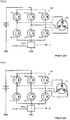
- FIG.6 shows a current pathway (indicated by a dashed line) during a state that the A-phase high-side FET1 is turned ON (the A-phase low-side FET4 is turned OFF), the B-phase high-side FET2 is turned OFF (the B-phase low-side FET5 is turned ON), and the C-phase high-side FET3 is turned OFF (the C-phase low-side FET6 is turned ON).
- FIG.7 shows a current pathway (indicated by a dashed line) during a state that the A-phase high-side FET1 is turned ON (the A-phase low-side FET4 is turned OFF), the B-phase high-side FET2 is turned ON (the B-phase low-side FET5 is turned OFF), and the C-phase high-side FET3 is turned OFF (the C-phase low-side FET6 is turned ON). It is clear from these current pathways of FIG. 6 and FIG.7 that the total value of phases that high-side FET is turned ON, appears in the current detector 106A as a detected current.
- the current detector 106A detects the motor current when any one of phases is turned ON and two phases are turned ON, and by utilizing a characteristic that the sum of currents of three phases is equal to zero, it is possible to detect each-phase currents of the A-phase, the B-phase and the C-phase.
- the current detection based on a one-shunt type current detector can detect each-phase currents. In this case, in order to perform the current detection while removing noise components such as rigging noises flowing in the current detector soon after the FET is turned ON, a certain period of time becomes necessary.
- each-phase motor currents are detected. Therefore, although it is necessary to maintain a one-phase ON-state and a two-phase ON-state for a necessary time for the current detection, in the case that each-phase duty command values become equal to each other, a problem that it is impossible to secure that a duration time, arises.
- Patent Document 1 Japanese Patent Application Laid-Open No. 2009-118621
- Patent Document 2 Japanese Patent Application Laid-Open No. 2007-112416
- the apparatus disclosed in Patent Document 1 when determining that the current detection is impossible, shifts the PWM phase by moving the phase of the PWM signal just a given amount, and secures a time becoming "PWM-ON" for the current detection necessary time to perform the current detection. That is, the apparatus disclosed in Patent Document 1, comprises a number of switching determining means that determines the number of switching elements of top arms that are turned on is an odd number or an even number in the case that a current detection advisability determining means determines that the current detection is impossible, and a phase moving means that moves the PWM signal of a given phase just a given amount to a given moving direction in the case that the number of switching determining means determines that it is an even number and moves the PWM signal of the given phase just the given amount to the opposite direction in the case that the number of switching determining means determines that it is an odd number, or moves the phase of a PWM signal having a maximum value of duty among each-phase PWM signals just the given amount to the given moving direction and moves the phase of
- the apparatus disclosed in Patent Document 2 shifts the PWM phase by that each-phase PWM signals have carriers with different phases respectively and perform the PWM output, and secures a time becoming "PWM-ON" for the current detection necessary time to perform the current detection. That is, in the apparatus disclosed in Patent Document 2, on a current pathway between a motor drive circuit and ground, a single current sensor for detecting a current value flowing the current pathway is provided, by shifting the phase of a saw-tooth wave for generating each-phase PWM signals and shifting timings of falling to a low level of each-phase PWM signals, based on the output signal of the single current sensor in a period until the elapse of a certain time starting from the timing of falling to the low level of V-phase PWM signal, the value of U-phase current flowing the motor can be obtained.
- Both of the apparatus disclosed in Patent Document 1 and the apparatus disclosed in Patent Document 2 detect each-phase currents of the motor by a one-shunt type current detector by shifting the PWM phase so as to maintain a one-phase ON-state and a two-phase ON-state for the current detection necessary time to perform the current detection.
- FIG.8 shows PWM waveforms (A-phase PWM, B-phase PWM and C-phase PWM) during the conventional PWM drive in the case of performing the current detection by a three-shunt type and changes in the motor currents (A-phase current, B-phase current and C-phase current) corresponding to these PWM waveforms, and shows that a time point t1 being a center of one PWM period is a current detection timing for all phases. Further, a dashed line of the A-phase current represents an A-phase average current, a dashed line of the B-phase current represents a B-phase average current and a dashed line of the C-phase current represents a C-phase average current.
- this three-shunt type current detection although variations in current within one PWM period are small and differences between each-phase average currents and detected each-phase current values are small, there is a problem that the current detectors for three phases are necessary.
- FIG.9 shows PWM waveforms (A-phase PWM, B-phase PWM and C-phase PWM) in the case of performing the current detection by a one-shunt type and changes in the motor currents (A-phase current, B-phase current and C-phase current) corresponding to these PWM waveforms, and shows a center of one PWM period by a time point t1.
- a dashed line of the A-phase current represents an A-phase average current
- a dashed line of the B-phase current represents a B-phase average current
- a dashed line of the C-phase current represents a C-phase average current.
- the current detection timing varies as time points t2 and t3, as shown in the A-phase current of this example, there is a problem that a variation in current within one PWM period becomes large.
- the time point t2 that the B-phase PWM is inputted is a current detection timing for the A-phase
- the time point t3 that the C-phase PWM is inputted is a current detection timing for the C-phase
- the current detection timing is instantaneous, since the motor average current is calculated within one PWM period, at the current detection timing, it is impossible to measure the average current, an error between the detected current value and the average current occurs.
- FIG. 9 shows that the A-phase current is corrected by a correction amount CR1 and shows that the C-phase current is corrected by a correction amount CR2.
- the present invention has been developed in view of the above-described circumstances, and an object of the present invention is to provide a motor control apparatus that detects each-phase motor currents of a motor by a one-shunt type current detector, contributes to downsizing, weight saving and cost-cutting, has less an operating sound and reduces a torque ripple, and an electric power steering apparatus mounting the above motor control apparatus.
- the present invention relates to a motor control apparatus that drive-controls a motor by an inverter based on each-phase duty command values of PWM and detects each-phase motor currents of said motor by a one-shunt type current detector, the above-described object of the present invention is achieved by that comprising: a current detection correcting section that calculates a current detection correction value based on a power-supply voltage of said motor, said each-phase duty command values, a back-EMF of said motor, said each-phase motor currents detected by said current detector, an arrangement information of said PWM, and an electric characteristic formula of said motor, thereby to correct said each-phase motor currents detected by said current detector to a motor average current by using said current detection correction value and to drive-control said motor
- the above-described object of the present invention is more effectively achieved by that: wherein said correction is performed by adding said current detection correction value to said each-phase motor currents detected by said current detector, or wherein said current detection correcting section obtains said current detection correction value by calculating each-phase PWM-ON/OFF patterns between current detection timings and given timings within one PWM period and their duration times, calculating a current change amount based on a phase current reference value from said electric characteristic formula, and calculating said motor average current within one PWM period from said current change amount, or wherein said given timings are timings that each PWM switches within one PWM period, or wherein said given timings are timings of a starting point, a middle point and an end point within one PWM period, or wherein said current detection correcting section comprises: a PWM-ON/OFF pattern duration time calculating section that calculates each-phase PWM-ON/OFF patterns between current detection timings and given timings within one PWM period and their duration time from said each-phase duty command values and said arrangement information of said
- a motor control apparatus of the present invention while using a cheap one-shunt type current detector, by calculating voltage patterns acting on each phase from PWM-ON/OFF patterns within one PWM period and their duration time and further adding a voltage fall due to motor resistance and so on, it is possible to calculate a motor current change pattern with respect to the detected current. Since it is possible to calculate a current change amount to the detected current within one PWM period, it is possible to correct the detected each-phase motor current values so as to correspond to the motor average current value by adding the calculated current change amount as the correction value.
- the present invention comprises a current detection correcting section that corrects detected each-phase motor current values that are detected by a one-shunt type current detector so as to correspond to a motor average current value in one PWM, based on each-phase duty command values in a PWM control section, a detected power-supply voltage value from a power-supply voltage detecting section, a back-EMF information of a motor, a PWM arrangement information in the PWM control section and an electric characteristic formula of the motor.
- the current detection correcting section calculates a correction current value by calculating each-phase ON/OFF patterns between current detection timings and given timings within one PWM period and their duration time based on the each-phase duty command values of the PWM and the PWM arrangement information, calculating the current change amount on the basis of A/D-converted each-phase motor current values based on the detected power-supply voltage value, the back-EMF information and the electric characteristic formula of the motor, and calculating an average current in one PWM period based on the current change amount.
- the correction is performed by adding the calculated correction current value to each-phase motor current values.
- FIG.10 shows a configuration example of the present invention corresponding to FIG.2 .
- the present invention is provided with a current detection correcting section 200 that calculates and outputs a current detection correction value Idct_h, and simultaneously provided with a power-supply voltage detecting section 210 that detects a power-supply voltage V(Vr) and an addition section 211 that adds the current detection correction value Idct_h calculated by the current detection correcting section 200 to a detected current value Im and inputs that added current value into a subtraction section 102B.
- the current detection correcting section 200 calculates and outputs the current detection correction value Idct_h that corrects the detected current value Im so as to correspond to the motor average current value, by using the power-supply voltage Vr of a power supply (battery) detected by the power-supply voltage detecting section 210, the detected current value Im detected by the current detector 106A, an each-phase PWM arrangement information PWM L and a back-EMF information EMF. And then, the current detection correction value Idct_h is added to the detected current value Im in the addition section 211, and is fed back to the subtraction section 102B.
- the current detection correction value Idct_h is added to the detected current value Im in the addition section 211, and is fed back to the subtraction section 102B.
- Calculating the current detection correction value Idct_h is performed by calculating the current change amount with respect to the detected current values of the motor current flowing at plural given timings being arbitrarily set within one PWM period and obtaining a time average value within one PWM period of the current change amount that is derived at every given timings.
- FIG.11 shows a principle of the present invention as a time chart (one PWM period), and illustrates appearances of change of an A-phase current (a solid line) with respect to an A-phase PWM, a B-phase PWM and a C-phase PWM and an A-phase average current (a dashed line). Then, FIG.11 shows cases that set plural given timings S 0 ⁇ S 6 as a start point (timing S 0 ) of one PWM period, an end point (timing S 6 ) of one PWM period and the times (timings S 1 ⁇ S 5 ) of switching ON/OFF for each phase.
- the calculation method of the current detection correction value Idct_h at each given timings (S 0 ⁇ S 6 ) will be described.
- the calculation method is different.
- V t ⁇ EMF t L di t dt + Ri t
- V is an applied voltage to the motor (the power-supply voltage)
- EMF is the back-EMF of the motor
- L is an inductance of the motor
- R is a resistance of the motor
- the first term of the right-hand side of Expression 2 represents the current change amount due to the applied voltage per phase
- the second term of the right-hand side of Expression 2 represents the current change amount due to a voltage fall caused by the current .
- the first term of the right-hand side of Expression 3, i.e. "1/L ⁇ [V(T)-EMF(T)] ⁇ Tf”, is the current change amount due to the applied voltage from the A/D timing to Tf.
- V(T) can be obtained by the sum of time of input voltage change patterns from the PWM side from the A/D timing to Tf. Details will be described later.
- the second term of the right-hand side of Expression 3, i.e. "R/L ⁇ I(T) ⁇ Tf” is the current change amount due to the voltage fall caused by the current which flows.
- the current change amount ⁇ Ib with respect to the reference current value after a time Tb[s] from the A/D timing can be obtained approximately by approximating the differential formula of Expression 2 by forward difference as Expression 6.
- the current change amount Fv (Tf) due to the applied voltage Vi of the inverter is obtained by subtracting the back-EMF EMF component "1/L ⁇ EMF(t) ⁇ Tf" from the applied voltage component "1/L ⁇ (V(t) ⁇ Tf)" from the inverter.
- the current change amount Fv(Tb) due to the applied voltage Vi of the inverter is obtained by subtracting the back-EMF EMF component "1/L ⁇ EMF(t) ⁇ Tb" from the applied voltage component "1/L ⁇ (V(t) ⁇ Tb)" from the inverter.
- the input voltage V(t) from the PWM side from the A/D timing to Tf is represented by plural PWM-ON/OFF patterns
- the input voltage V(t) is the sum of time of the applied voltage based on each PWM-ON/OFF pattern and a duration time.
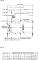
- the inverter applied voltage Vi of the in the above Expression 9 and Expression 10 is different depending on the PWM-ON/OFF patterns, when setting the power-supply voltage detected by the power-supply voltage detecting section 210 as "Vr", as shown in FIG.12 , regarding the PWM-ON/OFF patterns, it is possible to obtain 8 types of patterns (pattern No1 ⁇ No8).
- “ ⁇ " represents “ON” of PWM
- "-" represents "OFF” of PWM.
- the current detection correcting section 200 of the present invention calculates the current detection correction value Idct_h by using the above-described calculation formulas, the PWM patterns of FIG.12 , each-phase duty command values Da ⁇ Dc and so on.
- a configuration example of the current detection correcting section 200 comprises a PWM-ON/OFF pattern duration time calculating section 201, a current change amount calculating section 202 for the applied voltage component, a current change amount calculating section 203, and a current detection correction value calculating section 204.
- operations of the configuration example of the current detection correcting section 200 will be described.
- the PWM-ON/OFF pattern duration time calculating section 201 calculates the duration times T 1 ⁇ T m of each-phase PWM-ON/OFF pattern within a time from the A/D timing to the given timing, based on an each-phase PWM arrangement information PWM L and each-phase duty command values Da ⁇ Dc.
- the each-phase PWM arrangement information PWM L becomes that the A-phase PWM is arranged at a start point of PWM, the B-phase PWM is arranged after the elapse of a time ⁇ from the start point of PWM and the C-phase is arranged after the elapse of a time 2 ⁇ from the start point of PWM, and the duration times T 1 ⁇ T 8 of the PWM-ON/OFF pattern at each given timings S 1 ⁇ S 6 , is outputted as shown in FIG.14 .
- the PWM-ON/OFF pattern duration time calculating section 201 outputs the duration times T 1 ⁇ T m of the PWM-ON/OFF patterns based on the each-phase PWM arrangement information PWM L and the each-phase duty command values Da ⁇ Dc.
- “Da” is the A-phase duty command value
- “Db” is the B-phase duty command value
- “Dc” is the C-phase duty command value
- “T PWM" represents one PWM period time.
- each-phase PWM arrangement information PWM L when setting the PWM arrangement type as shown in FIG.11 for an example, since in the first current detection, having to secure a one-phase ON state for the time ⁇ , and in the second current detection, having to secure a two-phase ON state for the time ⁇ , the following two conditions are necessary.
- a PWM arrangement setting is performed so that a phase (here, A-phase) becoming the maximum duty value among duty values of three phases, is arranged at the start point of PWM, and a phase (here, B-phase) being the second largest is arranged after the elapse of the time ⁇ from the start point of PWM.
- contents for example, in the case of representing the arrangement of the start point of PWM as "#1", representing the arrangement after the elapse of the time ⁇ from the start point of PWM as "#2”, and representing the arrangement after the elapse of the time 2 ⁇ from the start point of PWM as "#3”, in the example of FIG.11 , the information is represented so that
- the current change amount calculating section 202 for the applied voltage component inputs the duration times T 1 ⁇ T m from the PWM-ON/OFF pattern duration time calculating section 201 and simultaneously inputs the detected power-supply voltage value Vr and the back-EMF EMF, and then calculates the current change amount Fv(Tf) or Fv(Tb) for the applied voltage component at every given timings by using Expression 9, Expression 10 and the applied voltage patterns of FIG.12 .
- Expression 9 since the timing S 0 is located before the A/D timing, the current change amount at the timing S 0 is calculated by Expression 9, and since the timings S 1 ⁇ S 6 are located after the A/D timing, the current change amount at the timings S 1 ⁇ S 6 are respectively calculated by Expression 10.
- the back-EMF information EMF although there are various signal generating means, for example, it is possible to obtain the back-EMF information EMF as described below. That is, since the shape of waveform of the motor back-EMF EMF is determined by a motor angle and there is a proportional relationship in the waveform amplitude in accordance with the number of revolutions, it is possible to obtain the motor back-EMF EMF based on an motor angle information, a back-EMF waveform model, and a revolution number information obtained by differentiating the motor angle information.
- the current change amount Fv(Tb) is calculated by the following Expression 12.
- FvS 1 0 0
- FvS 2 Ts 2 1 L 1 3 ⁇ Vr ⁇ T 5 ⁇ EMF A ⁇ Ts 2
- FvS 3 Ts 3 1 L 1 3 ⁇ Vr ⁇ T 5 ⁇ EMF A ⁇ Ts 3
- FvS 4 Ts 4 1 L 1 3 ⁇ Vr ⁇ T 5 ⁇ 2 3 ⁇ Vr ⁇ T 7 ⁇ EMF A ⁇ Ts 4
- FvS 5 Ts 5 1 L 1 3 ⁇ Vr ⁇ T 5 ⁇ T 4 ⁇ 2 3 ⁇ Vr ⁇ T 7 ⁇ EMF A ⁇ Ts 5
- FvS 6 Ts 6 1 L 1 3 ⁇ Vr ⁇ T 5 ⁇ T 4 ⁇ 2 3 ⁇ Vr ⁇ T 7 ⁇ EMF A ⁇ Ts 6
- the current change amount calculating section 203 inputs the current change amount Fv(Tf) or Fv(Tb) from the current change amount calculating section 202 for the applied voltage component and simultaneously inputs the motor current Im, and then calculates the current change amount ⁇ If or ⁇ Ib with respect to the detected current value for every given timings by using Expression 4 and Expression 7.
- the current change amount ⁇ If with respect to the detected current value for the timing S 0 is calculated by Expression 4
- the timings S 1 ⁇ S 6 are located after the A/D timing
- the current change amount ⁇ Ib with respect to the detected current value for the timings S 1 ⁇ S 6 are calculated by Expression 7.
- the current detection correction value calculating section 204 time-averages the current change amount ⁇ If or ⁇ Ib for every given timings that is outputted for every timings from the current change amount calculating section 203, and calculates and outputs the current detection correction value Idct_h.
- the given timing is arranged at seven points (S 0 ⁇ S 6 ) within one PWM period, by being limited to three points of timings, i.e. a start point, a middle point and an end point of one PWM period, internal calculations are simplified, and it becomes possible to calculate the current detection correction value Idct_h with few task load.
- the given timings are the start point (the timing S 0 ) of one PWM period before the current detection timing for the A-phase, the middle point (the timing S 1 ) after the current detection timing for the A-phase, and the end point (the timing S 2 ) after the current detection timing for the A-phase.
- the output of each section of the internal configuration of the current detection correcting section 200 changes as follows, since the calculation itself becomes few, the task load can be substantially reduced.
- the output of the PWM-ON/OFF pattern duration time calculating section 201 is simplified as shown in FIG. 16 .
- the current change amount calculating section 202 for the applied voltage component in the example of FIG.15 , since the timing S 0 is located before the A/D timing, the current change amount caused by applied voltage at the timing S 0 is calculated by the following expression 16, and since the timings S 1 and S 2 are located after the A/D timing, the current change amount caused by applied voltage at the timings S 1 and S 2 are calculated by the following expression 17.
- FvS 0 Ts 0 1 L 2 3 ⁇ Vr ⁇ T 2 ⁇ EMF A ⁇ Ts 0
- FvS 1 Ts 1 1 L 1 3 ⁇ Vr ⁇ T 5 ⁇ EMF A ⁇ Ts 1
- FvS 2 Ts 2 1 L 1 3 ⁇ Vr ⁇ T 5 ⁇ T 4 ⁇ 2 3 ⁇ Vr ⁇ T 7 ⁇ EMF A ⁇ Ts 2
- the current change amount calculating section 203 calculates the current change amount with respect to the detected current value for every given timings, in the example of FIG.15 , since the timing S 0 is located before the A/D timing, the current change amount with respect to the detected current value at the timing S 0 is calculated by the following expression 18, and since the timings S 1 and S 2 are located after the A/D timing, the current change amount with respect to the detected current value at the timings S 1 and S 2 are respectively calculated by the following expression 19.
- the current detection correction value calculating section 204 time-averages the current change amount for every given timings that is outputted for every timings from the current change amount calculating section 203, and calculates and outputs the current detection correction value Idct_h.
- Idct_h ⁇ I 0 + 2 ⁇ T ⁇ ⁇ I 1 + ⁇ I 2 4
- the above are descriptions about a three-phase motor, in the same way, it is possible to apply the present invention to other motor such as a two-phase motor. Further, although the above are descriptions about the electric power steering apparatus equipped with the compensation section, in the present invention, the compensation section is not indispensable.
Landscapes
- Engineering & Computer Science (AREA)
- Power Engineering (AREA)
- Chemical & Material Sciences (AREA)
- Combustion & Propulsion (AREA)
- Transportation (AREA)
- Mechanical Engineering (AREA)
- Control Of Motors That Do Not Use Commutators (AREA)
- Steering Control In Accordance With Driving Conditions (AREA)
- Power Steering Mechanism (AREA)
- Control Of Ac Motors In General (AREA)
Claims (8)
- Appareil de commande de moteur configuré pour, par une unité de commande, c'est-à-dire une UC, commander et entraîner un moteur (20) par un onduleur (106) sur la base de valeurs d'ordre de service de chaque phase (Da-Dc) d'une modulation d'impulsion en durée, PWM, et configuré pour détecter des courants de moteur de chaque phase (I(t)) dudit moteur (20) par un détecteur de courant de type à une dérivation (106A), caractérisé en ce que ledit appareil de commande de moteur comprend :une section de correction de détection de courant (200) configurée pour calculer une valeur de correction de détection de courant sur la base d'une tension d'alimentation en énergie dudit onduleur (106), desdites valeurs d'ordre de service de chaque phase, d'une information de force contre-électromotrice (contre-FEM) dudit moteur (20), desdits courants de moteur de chaque phase à un moment donné (S1 à S6) dans une période de PWM qui est détectée avec un moment (t) analogique-numérique, A/N, de détection de courant dudit détecteur de courant (106A), d'une information d'agencement de ladite PWM, et d'une formule de caractéristique électrique dudit moteur (20),dans lequel ladite section de correction de détection de courant (200) est configurée pour obtenir ladite valeur de correction de détection de courant en calculant des profils de MARCHE/ARRET de PWM de chaque phase entre ledit moment A/N de détection de courant et ledit moment donné dans ladite période de PWM, en calculant des durées de profils de MARCHE/ARRET de PWM (T1-Tm) sur la base d'informations d'agencement de PWM de chaque phase PWML et desdites valeurs d'ordre de service de chaque phase (Da-Dc), en calculant une quantité de modification de courant sur la base d'une valeur de référence de courant de phase à partir de ladite formule de caractéristique électrique, et en calculant un courant moyen de moteur dans ladite période de PWM à partir de ladite quantité de modification de courant,dans lequel ladite section de correction de détection de courant (200) est configurée pour calculer ladite quantité de modification de courant, dans lequel dans un cas où ledit moment donné existe avant ledit moment A/N de détection de courant, ladite quantité de modification de courant est calculée par approximation d'une formule différentielle par rétro-différence (Expression 3), et dans un cas où ledit moment donné existe après ledit moment A/N de détection de courant, ladite quantité de modification de courant est calculée par approximation de ladite formule différentielle par différence vers l'avant (Expression 6), etdans lequel ledit moteur (20) est commandé en entraînement par la réalisation d'une correction desdits courants de moteur de chaque phase en ledit courant moyen de moteur avec ladite valeur de correction de détection de courant, dans lequel


- Appareil de commande de moteur selon la revendication 1, dans lequel ladite correction est réalisée par addition de ladite valeur de correction de détection de courant auxdits courants de moteur de chaque phase.
- Appareil de commande de moteur selon la revendication 1 ou 2, dans lequel ledit moment donné est un moment auquel la PWM commute dans ladite période de PWM.
- Appareil de commande de moteur selon la revendication 1 ou 2, dans lequel ledit moment donné est un moment d'un point de départ, d'un point médian et d'un point final dans ladite période de PWM.
- Appareil de commande de moteur selon la revendication 1, dans lequel ladite section de correction de détection de courant (200) comprend :une section de calcul de durée de profil de MARCHE/ARRET de PWM (201) qui calcule des profils de MARCHE/ARRET de PWM de chaque phase entre un moment A/N de détection de courant et des moments donnés et lesdites durées à partir desdites valeurs d'ordre de service de chaque phase et desdites informations d'agencement de ladite PWM,une section de calcul de quantité de modification de courant (202) pour une composante de tension appliquée qui entre lesdits profils de MARCHE/ARRET de PWM, lesdites durées, une valeur détectée de ladite tension d'alimentation en énergie et lesdites informations de contre-FEM et calcule ladite quantité de modification de courant due à une tension appliquée pour tous les moments,une section de calcul de quantité de modification de courant (203) qui calcule ladite quantité de modification de courant sur la base d'une valeur de courant de phase détectée à partir de ladite quantité de modification de courant due à ladite tension appliquée et auxdits courants de moteur de chaque phase, etune section de calcul de valeur de correction de détection de courant (204) qui obtient ladite valeur de courant de correction par calcul dudit courant moyen à partir de ladite quantité de modification de courant.
- Appareil de commande de moteur selon la revendication 5, dans lequel ledit moment donné est un moment auquel chaque PWM commute dans ladite période de PWM.
- Appareil de commande de moteur selon la revendication 5, dans lequel ledit moment donné est un moment d'un point de départ, d'un point médian et d'un point final dans ladite période de PWM.
- Appareil de direction à énergie électrique caractérisé en ce qu'il est équipé de l'appareil de commande de moteur selon l'une quelconque des revendications 1, 2 et 3 à 7.
Applications Claiming Priority (2)
| Application Number | Priority Date | Filing Date | Title |
|---|---|---|---|
| JP2011198582A JP5724776B2 (ja) | 2011-09-12 | 2011-09-12 | モータ制御装置及び電動パワーステアリング装置 |
| PCT/JP2012/063168 WO2013038753A1 (fr) | 2011-09-12 | 2012-05-23 | Dispositif de commande de moteur et dispositif de direction à énergie électrique |
Publications (3)
| Publication Number | Publication Date |
|---|---|
| EP2621080A1 EP2621080A1 (fr) | 2013-07-31 |
| EP2621080A4 EP2621080A4 (fr) | 2015-08-05 |
| EP2621080B1 true EP2621080B1 (fr) | 2020-02-26 |
Family
ID=47882998
Family Applications (1)
| Application Number | Title | Priority Date | Filing Date |
|---|---|---|---|
| EP12805553.0A Active EP2621080B1 (fr) | 2011-09-12 | 2012-05-23 | Dispositif de commande de moteur et dispositif de direction à énergie électrique |
Country Status (6)
| Country | Link |
|---|---|
| US (1) | US8725357B2 (fr) |
| EP (1) | EP2621080B1 (fr) |
| JP (1) | JP5724776B2 (fr) |
| CN (1) | CN103155401B (fr) |
| BR (1) | BR112014005121B1 (fr) |
| WO (1) | WO2013038753A1 (fr) |
Families Citing this family (20)
| Publication number | Priority date | Publication date | Assignee | Title |
|---|---|---|---|---|
| KR20120029084A (ko) * | 2010-09-16 | 2012-03-26 | 주식회사 만도 | 전동식 파워 스티어링 장치 |
| JP5652434B2 (ja) * | 2012-06-15 | 2015-01-14 | 株式会社デンソー | モータ制御装置、及び、これを用いた電動パワーステアリング装置 |
| US9136787B2 (en) | 2012-10-25 | 2015-09-15 | Texas Instruments Incorporated | Back EMF monitor for motor control |
| CN104871425B (zh) * | 2013-04-17 | 2017-07-11 | 日本精工株式会社 | 多相电动机控制装置及使用该多相电动机控制装置的电动助力转向装置 |
| FR3009145B1 (fr) * | 2013-07-24 | 2017-06-09 | Thales Sa | Baie modulaire d'onduleurs et son procede de pilotage pour un ensemble de machines electriques depourvues de capteurs de position |
| WO2015068300A1 (fr) | 2013-11-11 | 2015-05-14 | 三菱電機株式会社 | Dispositif de conversion d'électricité |
| JP5865930B2 (ja) * | 2014-03-07 | 2016-02-17 | 三菱電機株式会社 | モータ制御装置 |
| CN105358410B (zh) * | 2014-05-29 | 2017-05-24 | 日本精工株式会社 | 电动助力转向装置 |
| DE102014213199A1 (de) | 2014-07-08 | 2016-01-14 | Conti Temic Microelectronic Gmbh | Verfahren und Vorrichtung zur Steuerung eines Betriebs eines Elektromotors |
| JP6422278B2 (ja) * | 2014-09-19 | 2018-11-14 | ルネサスエレクトロニクス株式会社 | 電力制御回路 |
| WO2016056083A1 (fr) | 2014-10-08 | 2016-04-14 | 三菱電機株式会社 | Dispositif de conversion de puissance et son procédé de commande, et dispositif de commande de direction assistée électrique |
| JP6622452B2 (ja) * | 2014-10-14 | 2019-12-18 | 日立グローバルライフソリューションズ株式会社 | モータ制御装置、圧縮機、空気調和機およびプログラム |
| JP6583000B2 (ja) * | 2016-01-07 | 2019-10-02 | 株式会社デンソー | 回転電機の制御装置 |
| JP6685765B2 (ja) * | 2016-02-25 | 2020-04-22 | 日立オートモティブシステムズ株式会社 | パワーステアリング装置の制御装置、及びそれを用いたパワーステアリング装置 |
| JP2018133853A (ja) * | 2017-02-13 | 2018-08-23 | 株式会社指月電機製作所 | インバータの電流検知方法、インバータの電流検知装置、アクティブフィルタ |
| US10784810B1 (en) * | 2019-04-29 | 2020-09-22 | Allegro Microsystems, Llc | Motor controller with accurate current measurement |
| DE102021131083A1 (de) * | 2020-11-30 | 2022-06-02 | Steering Solutions Ip Holding Corporation | Diagnose eines zustands einer eingangsenergie für eine elektrische servolenkung |
| US20240250543A1 (en) * | 2023-01-23 | 2024-07-25 | Northrop Grumman Systems Corporation | Quasi-load following (q-lf) high efficiency fault tolerant hybrid electric power system control method |
| US12401309B2 (en) | 2023-02-23 | 2025-08-26 | Allegro Microsystems, Llc | Three-phase motor current measurement |
| US12476566B2 (en) * | 2023-04-19 | 2025-11-18 | Hl Mando Corporation | Electronic control device using shunt resistor and current detection circuit |
Family Cites Families (18)
| Publication number | Priority date | Publication date | Assignee | Title |
|---|---|---|---|---|
| US6741060B2 (en) * | 2001-04-05 | 2004-05-25 | Delphi Technologies, Inc. | Method and system for controlling a permanent magnet machine during fault conditions |
| US6586898B2 (en) * | 2001-05-01 | 2003-07-01 | Magnon Engineering, Inc. | Systems and methods of electric motor control |
| US6734649B1 (en) * | 2003-01-08 | 2004-05-11 | Trw Automotive U.S. Llc | Dynamic tuning of current loop controller for a permanent magnet brushless motor |
| JP4039317B2 (ja) * | 2003-06-12 | 2008-01-30 | 株式会社ジェイテクト | 電動パワーステアリング装置 |
| JP4736805B2 (ja) * | 2003-10-07 | 2011-07-27 | 株式会社ジェイテクト | 電動パワーステアリング装置 |
| JP4405788B2 (ja) * | 2003-11-18 | 2010-01-27 | 日本精工株式会社 | 電動パワーステアリング装置の制御装置 |
| WO2005093939A1 (fr) * | 2004-03-26 | 2005-10-06 | Kabushiki Kaisha Yaskawa Denki | Contreleur de moteur |
| JP4458926B2 (ja) * | 2004-05-18 | 2010-04-28 | 三菱電機株式会社 | 電動パワーステアリング装置及びその制御方法 |
| JP5196211B2 (ja) * | 2005-09-22 | 2013-05-15 | 株式会社ジェイテクト | 車両用操舵装置 |
| JP4764785B2 (ja) * | 2006-08-23 | 2011-09-07 | ルネサスエレクトロニクス株式会社 | 同期電動機の制御装置 |
| JP5034633B2 (ja) * | 2006-10-17 | 2012-09-26 | 日本精工株式会社 | モータ駆動制御装置、モータ駆動制御方法及びモータ駆動制御装置を使用した電動パワーステアリング装置 |
| JP5252475B2 (ja) * | 2007-11-06 | 2013-07-31 | オムロンオートモーティブエレクトロニクス株式会社 | 多相電動機の制御装置 |
| DE102008001025A1 (de) * | 2008-04-07 | 2009-10-08 | Robert Bosch Gmbh | Verfahren und Vorrichtung zur Strommessung in Phasenleitungen |
| JP5308109B2 (ja) * | 2008-09-17 | 2013-10-09 | ルネサスエレクトロニクス株式会社 | 同期電動機の駆動システム |
| JP2010268647A (ja) * | 2009-05-18 | 2010-11-25 | Panasonic Corp | ブラシレスdcモータ駆動装置とそれを搭載した換気送風装置 |
| WO2010143452A1 (fr) * | 2009-06-08 | 2010-12-16 | 三菱電機株式会社 | Convertisseur de puissance |
| JP5614583B2 (ja) * | 2009-11-17 | 2014-10-29 | 株式会社ジェイテクト | モータ制御装置および車両用操舵装置 |
| JP5392025B2 (ja) * | 2009-11-24 | 2014-01-22 | 日本精工株式会社 | モータ制御装置及びそれを用いた電動パワーステアリング装置 |
-
2011
- 2011-09-12 JP JP2011198582A patent/JP5724776B2/ja not_active Expired - Fee Related
-
2012
- 2012-05-23 EP EP12805553.0A patent/EP2621080B1/fr active Active
- 2012-05-23 CN CN201280000444.4A patent/CN103155401B/zh not_active Expired - Fee Related
- 2012-05-23 WO PCT/JP2012/063168 patent/WO2013038753A1/fr not_active Ceased
- 2012-05-23 BR BR112014005121-6A patent/BR112014005121B1/pt not_active IP Right Cessation
- 2012-05-23 US US13/810,329 patent/US8725357B2/en active Active
Non-Patent Citations (1)
| Title |
|---|
| None * |
Also Published As
| Publication number | Publication date |
|---|---|
| EP2621080A1 (fr) | 2013-07-31 |
| US20130158808A1 (en) | 2013-06-20 |
| CN103155401B (zh) | 2015-09-02 |
| EP2621080A4 (fr) | 2015-08-05 |
| CN103155401A (zh) | 2013-06-12 |
| JP5724776B2 (ja) | 2015-05-27 |
| US8725357B2 (en) | 2014-05-13 |
| JP2013062913A (ja) | 2013-04-04 |
| WO2013038753A1 (fr) | 2013-03-21 |
| BR112014005121B1 (pt) | 2021-06-08 |
| BR112014005121A2 (pt) | 2017-06-13 |
Similar Documents
| Publication | Publication Date | Title |
|---|---|---|
| US8725357B2 (en) | Motor control apparatus and electric power steering apparatus | |
| US9667179B2 (en) | Multi-phase motor control apparatus and electric power steering apparatus using the same | |
| US7574294B2 (en) | Controller for electric power steering device | |
| US9248852B2 (en) | Electric power steering system | |
| EP2835906B1 (fr) | Dispositif de commande de moteur et dispositif de direction assistée électrique équipé de ce dispositif | |
| US9184690B2 (en) | Electrically driven power steering system and control apparatus for the same | |
| EP2518894B1 (fr) | Unité de commande de moteur et système de direction de véhicule | |
| US9979340B2 (en) | Apparatus for controlling three phase rotary electric machine reducing peak value of phase current | |
| EP2754601B1 (fr) | Appareil de commande de moteur et système de direction assistée électrique | |
| EP2410652A1 (fr) | Dispositif de commande de moteur et appareil de direction électrique | |
| US6810986B2 (en) | Electric power steering apparatus and control method therefor | |
| EP3020615B1 (fr) | Dispositif de direction assistée électrique | |
| JP6175704B2 (ja) | パワーステアリング装置およびパワーステアリング装置用制御装置 | |
| CN107155391A (zh) | 电动机控制装置及使用了该电动机控制装置的电动助力转向装置 | |
| JP5929521B2 (ja) | モータ制御装置及びそれを用いた電動パワーステアリング装置 | |
| JP6764564B2 (ja) | モータ制御装置 | |
| JP2003333882A (ja) | 多相モータ用制御装置 | |
| JP2004312930A (ja) | モータ制御装置 | |
| JP5061536B2 (ja) | モータ制御装置及びこれを用いた電動パワーステアリング制御装置 | |
| EP4589839A9 (fr) | Dispositif de conversion de puissance électrique, dispositif de commande de moteur et dispositif de direction assistée électrique | |
| JP2009027819A (ja) | モータ駆動制御装置及び電動パワーステアリング装置 |
Legal Events
| Date | Code | Title | Description |
|---|---|---|---|
| PUAI | Public reference made under article 153(3) epc to a published international application that has entered the european phase |
Free format text: ORIGINAL CODE: 0009012 |
|
| 17P | Request for examination filed |
Effective date: 20130108 |
|
| AK | Designated contracting states |
Kind code of ref document: A1 Designated state(s): AL AT BE BG CH CY CZ DE DK EE ES FI FR GB GR HR HU IE IS IT LI LT LU LV MC MK MT NL NO PL PT RO RS SE SI SK SM TR |
|
| AX | Request for extension of the european patent |
Extension state: BA ME |
|
| RBV | Designated contracting states (corrected) |
Designated state(s): AL AT BE BG CH CY CZ DE DK EE ES FI FR GB GR HR HU IE IS IT LI LT LU LV MC MK MT NL NO PL PT RO RS SE SI SK SM TR |
|
| DAX | Request for extension of the european patent (deleted) | ||
| RIN1 | Information on inventor provided before grant (corrected) |
Inventor name: MORI, KENJI Inventor name: IMAMURA, YOUSUKE Inventor name: MAEDA, MASAHIRO |
|
| RA4 | Supplementary search report drawn up and despatched (corrected) |
Effective date: 20150708 |
|
| RIC1 | Information provided on ipc code assigned before grant |
Ipc: B62D 119/00 20060101ALI20150702BHEP Ipc: B62D 6/00 20060101ALI20150702BHEP Ipc: B62D 101/00 20060101ALI20150702BHEP Ipc: H02P 6/00 20060101ALI20150702BHEP Ipc: H02M 7/5387 20070101ALI20150702BHEP Ipc: H02M 1/00 20070101ALI20150702BHEP Ipc: B62D 5/04 20060101ALI20150702BHEP Ipc: H02P 6/16 20060101AFI20150702BHEP Ipc: H02P 6/10 20060101ALI20150702BHEP Ipc: H02P 27/08 20060101ALI20150702BHEP |
|
| STAA | Information on the status of an ep patent application or granted ep patent |
Free format text: STATUS: EXAMINATION IS IN PROGRESS |
|
| 17Q | First examination report despatched |
Effective date: 20181015 |
|
| GRAP | Despatch of communication of intention to grant a patent |
Free format text: ORIGINAL CODE: EPIDOSNIGR1 |
|
| STAA | Information on the status of an ep patent application or granted ep patent |
Free format text: STATUS: GRANT OF PATENT IS INTENDED |
|
| INTG | Intention to grant announced |
Effective date: 20191021 |
|
| GRAS | Grant fee paid |
Free format text: ORIGINAL CODE: EPIDOSNIGR3 |
|
| GRAA | (expected) grant |
Free format text: ORIGINAL CODE: 0009210 |
|
| STAA | Information on the status of an ep patent application or granted ep patent |
Free format text: STATUS: THE PATENT HAS BEEN GRANTED |
|
| AK | Designated contracting states |
Kind code of ref document: B1 Designated state(s): AL AT BE BG CH CY CZ DE DK EE ES FI FR GB GR HR HU IE IS IT LI LT LU LV MC MK MT NL NO PL PT RO RS SE SI SK SM TR |
|
| REG | Reference to a national code |
Ref country code: GB Ref legal event code: FG4D |
|
| REG | Reference to a national code |
Ref country code: CH Ref legal event code: EP |
|
| REG | Reference to a national code |
Ref country code: AT Ref legal event code: REF Ref document number: 1238874 Country of ref document: AT Kind code of ref document: T Effective date: 20200315 |
|
| REG | Reference to a national code |
Ref country code: IE Ref legal event code: FG4D |
|
| REG | Reference to a national code |
Ref country code: DE Ref legal event code: R096 Ref document number: 602012068096 Country of ref document: DE |
|
| PG25 | Lapsed in a contracting state [announced via postgrant information from national office to epo] |
Ref country code: FI Free format text: LAPSE BECAUSE OF FAILURE TO SUBMIT A TRANSLATION OF THE DESCRIPTION OR TO PAY THE FEE WITHIN THE PRESCRIBED TIME-LIMIT Effective date: 20200226 Ref country code: RS Free format text: LAPSE BECAUSE OF FAILURE TO SUBMIT A TRANSLATION OF THE DESCRIPTION OR TO PAY THE FEE WITHIN THE PRESCRIBED TIME-LIMIT Effective date: 20200226 Ref country code: NO Free format text: LAPSE BECAUSE OF FAILURE TO SUBMIT A TRANSLATION OF THE DESCRIPTION OR TO PAY THE FEE WITHIN THE PRESCRIBED TIME-LIMIT Effective date: 20200526 |
|
| REG | Reference to a national code |
Ref country code: NL Ref legal event code: MP Effective date: 20200226 |
|
| REG | Reference to a national code |
Ref country code: LT Ref legal event code: MG4D |
|
| PG25 | Lapsed in a contracting state [announced via postgrant information from national office to epo] |
Ref country code: BG Free format text: LAPSE BECAUSE OF FAILURE TO SUBMIT A TRANSLATION OF THE DESCRIPTION OR TO PAY THE FEE WITHIN THE PRESCRIBED TIME-LIMIT Effective date: 20200526 Ref country code: LV Free format text: LAPSE BECAUSE OF FAILURE TO SUBMIT A TRANSLATION OF THE DESCRIPTION OR TO PAY THE FEE WITHIN THE PRESCRIBED TIME-LIMIT Effective date: 20200226 Ref country code: SE Free format text: LAPSE BECAUSE OF FAILURE TO SUBMIT A TRANSLATION OF THE DESCRIPTION OR TO PAY THE FEE WITHIN THE PRESCRIBED TIME-LIMIT Effective date: 20200226 Ref country code: HR Free format text: LAPSE BECAUSE OF FAILURE TO SUBMIT A TRANSLATION OF THE DESCRIPTION OR TO PAY THE FEE WITHIN THE PRESCRIBED TIME-LIMIT Effective date: 20200226 Ref country code: IS Free format text: LAPSE BECAUSE OF FAILURE TO SUBMIT A TRANSLATION OF THE DESCRIPTION OR TO PAY THE FEE WITHIN THE PRESCRIBED TIME-LIMIT Effective date: 20200626 Ref country code: GR Free format text: LAPSE BECAUSE OF FAILURE TO SUBMIT A TRANSLATION OF THE DESCRIPTION OR TO PAY THE FEE WITHIN THE PRESCRIBED TIME-LIMIT Effective date: 20200527 |
|
| PG25 | Lapsed in a contracting state [announced via postgrant information from national office to epo] |
Ref country code: NL Free format text: LAPSE BECAUSE OF FAILURE TO SUBMIT A TRANSLATION OF THE DESCRIPTION OR TO PAY THE FEE WITHIN THE PRESCRIBED TIME-LIMIT Effective date: 20200226 |
|
| PG25 | Lapsed in a contracting state [announced via postgrant information from national office to epo] |
Ref country code: ES Free format text: LAPSE BECAUSE OF FAILURE TO SUBMIT A TRANSLATION OF THE DESCRIPTION OR TO PAY THE FEE WITHIN THE PRESCRIBED TIME-LIMIT Effective date: 20200226 Ref country code: EE Free format text: LAPSE BECAUSE OF FAILURE TO SUBMIT A TRANSLATION OF THE DESCRIPTION OR TO PAY THE FEE WITHIN THE PRESCRIBED TIME-LIMIT Effective date: 20200226 Ref country code: DK Free format text: LAPSE BECAUSE OF FAILURE TO SUBMIT A TRANSLATION OF THE DESCRIPTION OR TO PAY THE FEE WITHIN THE PRESCRIBED TIME-LIMIT Effective date: 20200226 Ref country code: SM Free format text: LAPSE BECAUSE OF FAILURE TO SUBMIT A TRANSLATION OF THE DESCRIPTION OR TO PAY THE FEE WITHIN THE PRESCRIBED TIME-LIMIT Effective date: 20200226 Ref country code: RO Free format text: LAPSE BECAUSE OF FAILURE TO SUBMIT A TRANSLATION OF THE DESCRIPTION OR TO PAY THE FEE WITHIN THE PRESCRIBED TIME-LIMIT Effective date: 20200226 Ref country code: SK Free format text: LAPSE BECAUSE OF FAILURE TO SUBMIT A TRANSLATION OF THE DESCRIPTION OR TO PAY THE FEE WITHIN THE PRESCRIBED TIME-LIMIT Effective date: 20200226 Ref country code: CZ Free format text: LAPSE BECAUSE OF FAILURE TO SUBMIT A TRANSLATION OF THE DESCRIPTION OR TO PAY THE FEE WITHIN THE PRESCRIBED TIME-LIMIT Effective date: 20200226 Ref country code: PT Free format text: LAPSE BECAUSE OF FAILURE TO SUBMIT A TRANSLATION OF THE DESCRIPTION OR TO PAY THE FEE WITHIN THE PRESCRIBED TIME-LIMIT Effective date: 20200719 Ref country code: LT Free format text: LAPSE BECAUSE OF FAILURE TO SUBMIT A TRANSLATION OF THE DESCRIPTION OR TO PAY THE FEE WITHIN THE PRESCRIBED TIME-LIMIT Effective date: 20200226 |
|
| REG | Reference to a national code |
Ref country code: AT Ref legal event code: MK05 Ref document number: 1238874 Country of ref document: AT Kind code of ref document: T Effective date: 20200226 |
|
| REG | Reference to a national code |
Ref country code: DE Ref legal event code: R097 Ref document number: 602012068096 Country of ref document: DE |
|
| PLBE | No opposition filed within time limit |
Free format text: ORIGINAL CODE: 0009261 |
|
| STAA | Information on the status of an ep patent application or granted ep patent |
Free format text: STATUS: NO OPPOSITION FILED WITHIN TIME LIMIT |
|
| PG25 | Lapsed in a contracting state [announced via postgrant information from national office to epo] |
Ref country code: AT Free format text: LAPSE BECAUSE OF FAILURE TO SUBMIT A TRANSLATION OF THE DESCRIPTION OR TO PAY THE FEE WITHIN THE PRESCRIBED TIME-LIMIT Effective date: 20200226 Ref country code: IT Free format text: LAPSE BECAUSE OF FAILURE TO SUBMIT A TRANSLATION OF THE DESCRIPTION OR TO PAY THE FEE WITHIN THE PRESCRIBED TIME-LIMIT Effective date: 20200226 Ref country code: LI Free format text: LAPSE BECAUSE OF NON-PAYMENT OF DUE FEES Effective date: 20200531 Ref country code: MC Free format text: LAPSE BECAUSE OF FAILURE TO SUBMIT A TRANSLATION OF THE DESCRIPTION OR TO PAY THE FEE WITHIN THE PRESCRIBED TIME-LIMIT Effective date: 20200226 Ref country code: CH Free format text: LAPSE BECAUSE OF NON-PAYMENT OF DUE FEES Effective date: 20200531 |
|
| 26N | No opposition filed |
Effective date: 20201127 |
|
| PG25 | Lapsed in a contracting state [announced via postgrant information from national office to epo] |
Ref country code: PL Free format text: LAPSE BECAUSE OF FAILURE TO SUBMIT A TRANSLATION OF THE DESCRIPTION OR TO PAY THE FEE WITHIN THE PRESCRIBED TIME-LIMIT Effective date: 20200226 Ref country code: SI Free format text: LAPSE BECAUSE OF FAILURE TO SUBMIT A TRANSLATION OF THE DESCRIPTION OR TO PAY THE FEE WITHIN THE PRESCRIBED TIME-LIMIT Effective date: 20200226 |
|
| REG | Reference to a national code |
Ref country code: BE Ref legal event code: MM Effective date: 20200531 |
|
| GBPC | Gb: european patent ceased through non-payment of renewal fee |
Effective date: 20200526 |
|
| PG25 | Lapsed in a contracting state [announced via postgrant information from national office to epo] |
Ref country code: LU Free format text: LAPSE BECAUSE OF NON-PAYMENT OF DUE FEES Effective date: 20200523 |
|
| PG25 | Lapsed in a contracting state [announced via postgrant information from national office to epo] |
Ref country code: IE Free format text: LAPSE BECAUSE OF NON-PAYMENT OF DUE FEES Effective date: 20200523 Ref country code: GB Free format text: LAPSE BECAUSE OF NON-PAYMENT OF DUE FEES Effective date: 20200526 |
|
| PG25 | Lapsed in a contracting state [announced via postgrant information from national office to epo] |
Ref country code: BE Free format text: LAPSE BECAUSE OF NON-PAYMENT OF DUE FEES Effective date: 20200531 |
|
| PG25 | Lapsed in a contracting state [announced via postgrant information from national office to epo] |
Ref country code: TR Free format text: LAPSE BECAUSE OF FAILURE TO SUBMIT A TRANSLATION OF THE DESCRIPTION OR TO PAY THE FEE WITHIN THE PRESCRIBED TIME-LIMIT Effective date: 20200226 Ref country code: MT Free format text: LAPSE BECAUSE OF FAILURE TO SUBMIT A TRANSLATION OF THE DESCRIPTION OR TO PAY THE FEE WITHIN THE PRESCRIBED TIME-LIMIT Effective date: 20200226 Ref country code: CY Free format text: LAPSE BECAUSE OF FAILURE TO SUBMIT A TRANSLATION OF THE DESCRIPTION OR TO PAY THE FEE WITHIN THE PRESCRIBED TIME-LIMIT Effective date: 20200226 |
|
| PG25 | Lapsed in a contracting state [announced via postgrant information from national office to epo] |
Ref country code: MK Free format text: LAPSE BECAUSE OF FAILURE TO SUBMIT A TRANSLATION OF THE DESCRIPTION OR TO PAY THE FEE WITHIN THE PRESCRIBED TIME-LIMIT Effective date: 20200226 Ref country code: AL Free format text: LAPSE BECAUSE OF FAILURE TO SUBMIT A TRANSLATION OF THE DESCRIPTION OR TO PAY THE FEE WITHIN THE PRESCRIBED TIME-LIMIT Effective date: 20200226 |
|
| PGFP | Annual fee paid to national office [announced via postgrant information from national office to epo] |
Ref country code: FR Payment date: 20220408 Year of fee payment: 11 Ref country code: DE Payment date: 20220329 Year of fee payment: 11 |
|
| REG | Reference to a national code |
Ref country code: DE Ref legal event code: R119 Ref document number: 602012068096 Country of ref document: DE |
|
| PG25 | Lapsed in a contracting state [announced via postgrant information from national office to epo] |
Ref country code: DE Free format text: LAPSE BECAUSE OF NON-PAYMENT OF DUE FEES Effective date: 20231201 |
|
| PG25 | Lapsed in a contracting state [announced via postgrant information from national office to epo] |
Ref country code: FR Free format text: LAPSE BECAUSE OF NON-PAYMENT OF DUE FEES Effective date: 20230531 |