EP2622689B1 - Querverbinder mit markierung - Google Patents
Querverbinder mit markierung Download PDFInfo
- Publication number
- EP2622689B1 EP2622689B1 EP11758486.2A EP11758486A EP2622689B1 EP 2622689 B1 EP2622689 B1 EP 2622689B1 EP 11758486 A EP11758486 A EP 11758486A EP 2622689 B1 EP2622689 B1 EP 2622689B1
- Authority
- EP
- European Patent Office
- Prior art keywords
- connector
- cross
- marking
- housing
- contact
- Prior art date
- Legal status (The legal status is an assumption and is not a legal conclusion. Google has not performed a legal analysis and makes no representation as to the accuracy of the status listed.)
- Not-in-force
Links
- 238000002372 labelling Methods 0.000 title 1
- 238000007373 indentation Methods 0.000 claims description 3
- 238000000034 method Methods 0.000 claims description 3
- 230000000007 visual effect Effects 0.000 claims description 3
- 239000003550 marker Substances 0.000 description 12
- 230000002427 irreversible effect Effects 0.000 description 9
- 230000002441 reversible effect Effects 0.000 description 5
- 239000000729 antidote Substances 0.000 description 4
- 239000004020 conductor Substances 0.000 description 3
- 239000003795 chemical substances by application Substances 0.000 description 2
- 238000004049 embossing Methods 0.000 description 2
- 238000000926 separation method Methods 0.000 description 2
- 240000006829 Ficus sundaica Species 0.000 description 1
- 239000011810 insulating material Substances 0.000 description 1
- 238000009413 insulation Methods 0.000 description 1
Images





Classifications
-
- H—ELECTRICITY
- H01—ELECTRIC ELEMENTS
- H01R—ELECTRICALLY-CONDUCTIVE CONNECTIONS; STRUCTURAL ASSOCIATIONS OF A PLURALITY OF MUTUALLY-INSULATED ELECTRICAL CONNECTING ELEMENTS; COUPLING DEVICES; CURRENT COLLECTORS
- H01R9/00—Structural associations of a plurality of mutually-insulated electrical connecting elements, e.g. terminal strips or terminal blocks; Terminals or binding posts mounted upon a base or in a case; Bases therefor
- H01R9/22—Bases, e.g. strip, block, panel
- H01R9/24—Terminal blocks
- H01R9/26—Clip-on terminal blocks for side-by-side rail- or strip-mounting
- H01R9/2675—Electrical interconnections between two blocks, e.g. by means of busbars
-
- H—ELECTRICITY
- H01—ELECTRIC ELEMENTS
- H01R—ELECTRICALLY-CONDUCTIVE CONNECTIONS; STRUCTURAL ASSOCIATIONS OF A PLURALITY OF MUTUALLY-INSULATED ELECTRICAL CONNECTING ELEMENTS; COUPLING DEVICES; CURRENT COLLECTORS
- H01R9/00—Structural associations of a plurality of mutually-insulated electrical connecting elements, e.g. terminal strips or terminal blocks; Terminals or binding posts mounted upon a base or in a case; Bases therefor
- H01R9/22—Bases, e.g. strip, block, panel
- H01R9/24—Terminal blocks
- H01R9/26—Clip-on terminal blocks for side-by-side rail- or strip-mounting
- H01R9/2683—Marking plates or tabs
-
- H—ELECTRICITY
- H01—ELECTRIC ELEMENTS
- H01R—ELECTRICALLY-CONDUCTIVE CONNECTIONS; STRUCTURAL ASSOCIATIONS OF A PLURALITY OF MUTUALLY-INSULATED ELECTRICAL CONNECTING ELEMENTS; COUPLING DEVICES; CURRENT COLLECTORS
- H01R31/00—Coupling parts supported only by co-operation with counterpart
- H01R31/08—Short-circuiting members for bridging contacts in a counterpart
Definitions
- the present invention relates to a cross connector according to the preamble of claim 1.
- the publication DE 42 23 540 A1 shows a cross connector having a marking device for each electrical contact in the visible upper edge region of a transverse bar of the cross connector.
- the marking device enables a reversible or irreversible arrangement or removal of a marking for each of the contact tabs.
- a loose mark may be lost and / or the installer may forget to place or remove the mark, such that in such terminal clamping arrangements, it is not certain that the electrical contact of one terminal through the cross connector is actually connected or disengaged from one or more adjacent terminal blocks taken.
- the FR 2 190 319 shows a cross connector for a terminal block assembly having contact terminals, which are adapted to be contacted from the outside of the housing of the terminal to screw terminals.
- the actual cross connector is realized with an insulated line which has been stripped in the region of the contact terminals and around which the contact terminals are wound around. A mark is not provided on the actual contact terminals. There is also no housing on the cross connector. Between adjacent contact terminals, however, the cross-connecting line is surrounded by the conductor insulation.
- the object of the invention is to provide a simple and cost-effective way for a fitter to mark the contact situation of the cross connector error-free.
- the loosening or arranging the contact terminals and the at least one marking is carried out either reversibly or irreversibly.
- the release of the mark is irreversible.
- the release of the label is reversible.
- the marking of the cross connector therefore requires no additional operation, but takes place simultaneously with the release of the contact terminal. In addition, it is very fast and is very error-prone possible.
- the marking makes it immediately apparent to the installer whether or not a contact connection is provided on the transverse connector. The marker therefore marks the presence or absence of a contact terminal on the cross connector.
- all markings provided on the cross connector comprises only markings which are provided for marking contact connections of the transverse connector.
- the markings arranged on the transverse connector are each provided in a uniform manner either for marking the contact connections arranged on the transverse connector, or for marking the contact connections which are missing on the transverse connector.
- an embodiment in which both the intended and the missing contact connections are marked is preferred. In this embodiment, however, the intended and missing contact terminals are distinguishable from each other.
- the invention allows an installer to detect the presence of a contact terminal on a cross connector, even if the cross connector is disposed in an electrical housing or an assembly of such electrical enclosures and the contact terminals themselves are not visible.
- the means for arranging a marking and / or the markings are preferably provided on the transverse connector such that the marking arranged on the transverse connector is arranged in a viewing region.
- the marking arranged on the transverse connector is arranged at least partially on an end of the transverse connector opposite the contact connections. This makes it visible to the fitter even when installed in the electrical housing or the arrangement of such electrical enclosures cross connector.
- the marking of a housing of the cross connector structurally, in particular by a recess and / or survey, and / or color differs so that it is visible and / or tactile.
- the color distinctness also includes a light / dark contrast.
- the means provided on the transverse connector for arranging a marking or markings are respectively arranged on a contact connection assigned to them or on the housing of the transverse connector.
- each contact terminal that can be arranged on the cross connector is assigned a respective marking.
- the means for arranging a marking is a strip which is markable and is arranged on the housing of the cross connector.
- the housing of the cross connector is preferably formed integrally with the means for arranging the marking.
- the transverse connector by means of a marking tool, in particular a pair of pliers, is marked with the marking, in particular by embossing, scoring, peeling, cutting or mechanical removal.
- the markings are preferably provided in one piece with the housing of the transverse connector, or they are particularly preferably detachable from it, in particular reversibly.
- the integrally provided with the housing markings are preferably by breaking, in particular at a predetermined breaking point, from the cross connector solvable. The marking and removal of the contact connection are irreversible.
- a means for arranging a mark is provided for each contact terminal which can be arranged on the cross connector.
- the arrangement of a contact connection or the release of a contact connection takes place only simultaneously with the arrangement or release of the marking.
- the means for arranging the marking are preferably fastening means such as spring / groove, latching or snap elements, with which the markings can be arranged on the cross connector.
- a marking is adjustable by means of a means for arranging the marking, in particular displaceable or rotatable, so that the marking is adjusted when loosening or arranging a contact connection.
- a means for arranging the marking in particular displaceable or rotatable, so that the marking is adjusted when loosening or arranging a contact connection.
- This can be realized for example by means of latching and / or snap elements.
- the means for arranging the mark is indeed arranged on the housing, but at least the markings and / or optionally also the means for arranging the mark are not formed integrally therewith.
- the means for arranging a marking and / or the markings are respectively arranged on the contact connection assigned to them.
- the contact terminals are preferably detachable from the cross connector.
- a marking associated with a contact connection is simultaneously detachable, in particular reversible, from the transverse connector when the contact connection assigned to it is released.
- the mark is attached to the contact terminal or made in one piece with this, so that it is releasable (preferably irreversibly) together with the contact terminal of the cross connector.
- a means designed as a bar for arranging a mark when releasing the contact terminal is simultaneously markable.
- the cross connector has a viewing area through which the contact terminals are visible.
- This cross connector is also provided for an electrical housing or an electrical housing arrangement, in particular for a modular terminal arrangement, wherein at least two contact terminals, which are designed as plugs or as sockets, are provided on the transverse connector.
- the contact terminals arranged in the transverse connector and / or the contact terminals not arranged in the transverse connector each form a marking.
- the means for arranging the marking of this embodiment is in a preferred embodiment, a receptacle of the cross connector, in which the contact terminal can be arranged.
- each contact connection which can be arranged on the transverse connector.
- the cross connector preferably has a housing, wherein the viewing area is a recess in the housing or a transparent part of the housing.
- the field of view is the respective one Recording for the contact connection.
- it is preferably one or, in each case, it is a window for each contact connection that can be arranged on the transverse connector.
- the window can be formed both as a recess in the housing and as a transparent part of the housing.
- the housing of the cross connector is transparent.
- an electrical housing or an arrangement of such electrical housings in particular a critiquenklemman extract, with at least two receptacles for receiving contact terminals of a particular cross connector according to the invention with which accessible through the receptacle electrical contact with the accessible by further recordings electrical contacts of the electrical housing or the arrangement of such electrical housings is electrically conductively connected, wherein on each receptacle a means for arranging a mark or a mark is provided, with the presence of a arranged on the transverse connector contact terminal and / or not arranged on the cross connector contact terminal is marked or markable ,
- An electrical housing according to the invention is a housing in which electrical contacts, for example, conductor or plug-in connections, can be connected to one another by means of a cross connector.
- An arrangement of such electrical housings according to the invention is an arrangement of a plurality of, in particular juxtaposed, housings in which in each case at least one electrical contact, for example a conductor or plug connection, is arranged, which can be connected to one another by means of the cross connector.
- a marking in the sense of the invention is provided for identifying intended and / or not provided contact terminals in the electrical housing or the arrangement of such electrical housings used cross connector.
- the markings arranged on the electrical housing or the arrangement of such electrical housings are each provided uniformly either for marking the contact terminals arranged on the electrical housing or the arrangement of such electrical housings, or for marking those missing on the electrical housing or the arrangement of such electrical housings Contact connections.
- an embodiment in which both the intended and the missing contact connections are marked is preferred. In this embodiment, however, the intended and missing contact terminals are distinguishable from each other.
- the arrangement of such electrical housings is a terminal clamping arrangement with at least two rowed terminal blocks, which have the receptacles for receiving the contact terminals of the particular cross connector according to the invention.
- the terminal blocks are to be understood as electrical housing in the context of the invention.
- the markers also differ structurally from a terminal block housing, in particular by a recess and / or elevation, and / or color, so that it is easily recognizable and / or palpable by the fitter.
- the object is further achieved with a method for identifying provided on a cross connector contact terminals, in particular in an electrical housing or an arrangement of such electrical enclosures, wherein upon release of a contact terminal from the cross connector simultaneously the associated marking is released from the cross connector, or wherein at Separating the contact terminal by means of a marking tool at the same time a means for arranging a mark with the contact terminal associated marking is marked, or being provided on a cross-connector receiving electrical housing or an arrangement of such electrical housings markings in the Arranging the cross connector in the electrical housing or the arrangement of such electrical housings are adjusted by means of the transverse connector arranged contact terminals.
- a marking tool for a cross-connector which has release means for separating a contact terminal from the cross connector, wherein the marking tool also has marking means with which a means for arranging a mark when disconnecting the contact terminal irreversibly markable with a mark associated with the contact terminal.
- the marking tool is preferably designed as a hand tool, for example a pair of pliers, or as a machine, for example a punch.
- the separating means are preferably provided as cutting, with which the contact terminal of the cross connector is irreversibly releasable.
- the marking means are preferably provided as cutting, stamping, notching or embossing means, so that the means for arranging a marking is irreversibly marked during irreversible separation of the contact connection.
- Fig. 1 shows a cross connector 1 according to the invention shown here.
- the cross connector 1 shown here has four contact terminals 12 which are arranged on a housing 11 of the cross connector 1.
- the housing 11 is integrally formed here. But it is also preferred an embodiment in which the housing 11 of the cross connector 1 one or more pieces is formed so that the contact terminals 12 are separable from each other, so that the length of the cross connector 1 and thus the number of the cross connector 1 vorsehbaren contact terminals 12 is adjustable.
- the contact terminals 12 are formed here as a plug and resilient. But there are also preferred contact terminals 12, which are not resilient, such as pins, or which are designed as sockets.
- Each contact terminal 12 is assigned a mark 13 here. In principle, however, it is also preferable to provide certain contact connections, for example the first or last contact connection, without a marking.
- the marking 13 is arranged on the contact connection 12 via a web 132 in such a way that it is arranged on an end 111 of the transverse connector 1 lying opposite the contact connection 12.
- the marker 13 is structurally and / or color different from the housing 11 of the cross connector 1 and visible at the contact terminal 12 opposite end 11 of the cross connector 1 and / or palpable.
- a means 131 for arranging the mark 13 is provided for each mark 13 in the housing 11 of the cross connector 1, that is formed here as a recess into which an antidote 133 for arranging the mark 13th engages which is provided at the mark 13.
- the antidote 133 is formed here as a corresponding to the recess Anformung.
- snap elements or other elements may be used as the means 131 and the means 133 for locating the mark 13.
- the means 131 for arranging the marking 13 and the counter means 133 (web reception or the like) for arranging the marking 13 are preferably made of an insulating material.
- Each contact terminal 12 of the cross connector 1 is preferably provided in this irreversibly detachable.
- the arranged on the web 132 on the contact terminal 12 mark 13 is released with. In this embodiment, therefore, any missing contact terminal 12 is immediately recognizable by the missing associated therewith marker 13.
- Fig. 2 shows an electrical housing assembly 3, which is designed here as a terminal clamping arrangement, in which two cross connector 1 can be arranged.
- the terminal clamping arrangement 3 is here formed of four adjoining electrical housings 2, which are designed here as terminal blocks. In the following, therefore, the terms electrical housing 2 and terminal are used synonymously.
- the terminal block assembly 3 from the terminal blocks 2 provided here can be arranged on a mounting rail (not shown).
- the terminal blocks 2 have receptacles 4 accessible electrical contacts (not shown), which are connected by means of the cross connector 1 electrically contacting each other.
- Each of the terminal blocks 2 has two receptacles 4 for receiving a contact terminal 12.
- the recordings 4 associated markers 13 are displaceable here, namely height adjustable, provided.
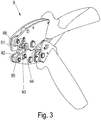
- Fig. 3 shows a marking tool 9 for marking a cross connector according to the invention 1.
- the marking tool 9 is designed as a pair of pliers. In the following, the terms marking tool 9 and pliers are used synonymously.
- the pliers 9 has two mutually corresponding first release means 91, 92, which are provided here as cutting, and which are provided for a longitudinal section, so that the cross connector 1 by means of these first separating means 91, 92 can be severed.
- the pliers 9 two mutually corresponding second release means 95, 96, which are also provided as cutting but for a cross section, and with which a contact terminal 12 which is fixedly disposed on the cross connector 1, irreversible from the cross connector 1 is separable.
- the marking tool 9 as a marking means 93, 94 for marking the cross connector 1 on two further cutting, which are spaced from the first and second separating means 91, 92, 95, 96, and with which a arranged on the cross connector 1 means 134 (s. Fig. 4 (b) ) for arranging a marker 13 when disconnecting the contact terminal 12 is irreversible markable.
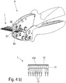
- Fig. 4 shows in Fig. 4 (a) a transverse connector 1 according to the invention, which is inserted into the marking tool 9.
- the pliers 9 is closed, so that the contact terminal 12 and its associated mark 13 are separated from the cross connector 1 irreversible.
- the Fig. 4 (b) also shows the marked cross connector 1.
- the cross connector 1 has a housing 11, are arranged on the contact terminals 12 which are formed here as pins. On the housing 11, a means 134 for arranging the mark 13, which is formed as a bar, integrally arranged. Between the contact terminals 12 disposed on the cross connector 1 is missing a contact terminal 12. This missing contact terminal 12 is through the Mark associated with it 13, which is here designed as a cut corner marked.
- the marker 13 is arranged at the opposite end of the contact terminals 12 111 of the cross connector 1, so that it is visible in arranged in a terminal clamping arrangement 3 cross connector 1 for a fitter.
- FIG. 4 (c) shows a further cross connector 1, which is inserted into the marking tool 9.
- Fig. 4 (d) shows a further cross connector 1, which is inserted into the marking tool 9.
- Fig. 4 (d) shows a further cross connector 1, which is inserted into the marking tool 9.
- Fig. 4 (d) shows a further cross connector 1, which is inserted into the marking tool 9.
- Fig. 4 (d) shows a further cross connector 1, which is inserted into the marking tool 9.
- Fig. 4 (d) shows a further cross connector 1, which is inserted into the marking tool 9.
- Fig. 4 (d) shows a further cross connector 1, which is inserted into the marking tool 9.
- Fig. 4 (d) shows a further cross connector 1, which is inserted into the marking tool 9.
- Fig. 4 (d) shows a further cross connector 1, which is inserted into the marking tool 9.
- Fig. 4 (d) shows a further cross connector 1, which is inserted into the marking tool 9.
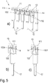
- the Fig. 5 shows in Fig. 5 (a) a further embodiment of a cross connector 1 according to the invention with here a total of six contact terminals 12, in Fig. 5 (b) a section of the cross connector of Fig. 5 (a) with a contact connection, and in Fig. 5 (c) a section of another embodiment of a cross connector according to the invention with a contact terminal.
- the in the Fig. 5 1 all have a housing 11, in which contact terminals 12 are arranged, each of which a marker 13 is assigned.
- the markings 13 are arranged on the contact terminals 12 facing away from the end 111 of the cross connector 1. All markings 13 of the cross connector 1 are structurally and / or color different from their housing 11 and in each case visible and / or palpable on the associated contact terminal 12 opposite end 11.
- a removable marker 13 is provided on the cross connector 1, which are connected in the embodiment shown here in each case with its associated contact terminal 12 by a web 132, so that these markers 13 are always the cross connector 1 together with their respective associated contact terminal 12 can be removed.
- a means 131 for arranging the marking 13 is provided for each marking 13 in the housing 11 of the transverse connector 1, that is formed here as a groove into which an antidote 133 for arranging the marker 13 (not shown here) engages.
- Each of these contact terminals 12 of the cross connector 1 is vorzugseise irreversibly releasably provided in this.
- the arranged on the web 132 on the contact terminal 12 mark 13 is released with. In this embodiment, therefore, any missing contact terminal 12 is immediately recognizable by the missing associated therewith marker 13.
- the cross connector 1 has a groove 14 in the housing 11 which acts as an engagement for a removal tool, e.g. a screwdriver / robot tool (not shown) is provided.
- a removal tool e.g. a screwdriver / robot tool (not shown) is provided.
- the embodiment of the cross connector 1 of Fig. 5 (c) differs from this embodiment of the Fig. 5 (a) and (b) only in that the groove 14 is not continued in the webs 132, but only in the housing 11 of the cross connector 1. Thus, the web appears in this embodiment as a bridge 1321, which interrupts the groove 14.
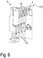
- the Fig. 6 shows an electrical housing 2, in which a further embodiment of a cross connector 1 according to the invention is arranged.
- the electrical housing 2 is designed as a terminal block.
- this cross connector 1 has a first and last contact terminal 12, which are not removable, and four arranged between the first and last contact terminal 12 removable contact terminals 12th
- the first and last contact terminals 12 are the Fig. 6 not marked by a marker 13.
- the markings 13 of the contact terminals 12 arranged between the first and last contact connection 12 of this embodiment are provided laterally of the transverse connector 1 and can not be seen and / or felt by the side opposite the contact terminals 12.
- the cross connector 1 extends beyond the electrical housing 2 to such an extent that the markings 13 of the contact terminals 12 arranged between the first and last contact connection 12 are visible laterally of the transverse connector 1.
- the markers 13 are removable only together with their associated contact terminals 12.
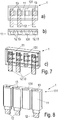
- Fig. 7 - 8 show further embodiments according to the invention cross connector. 1
- the Fig. 7 shows a cross connector 1 with a transparent housing 11, so that each arranged in a receptacle 131 of the housing 11 contact terminals 12 are visible through the housing 11 therethrough.
- the means for arranging the mark 131 is therefore here in each case by the receptacle 131 for the contact terminal 12, and the mark 13 is here formed in each case by the contact terminal 12 itself.
- the entire housing 11 of the cross connector 1 is therefore formed here as a viewing area through which the contact terminals 12 are visible.
- the terms means for arranging the mark 131 and receiving a contact terminal can be used interchangeably.
- the terms contact terminal 12 and marker 13 may be used interchangeably.
- the terms visual range and housing 11 can be used synonymously.
- Fig. 8 is the viewing area in each case a recess which is formed by a receptacle for a contact terminal 12 at the opposite end of the contact terminals 12 111 of the cross connector 1.
- the contact terminals 12 themselves form the markings 13
- the receptacles 131 for the contact terminals 12 respectively form the means for arranging the marking 131.
- the terms means for arranging the mark 131, field of view and receiving a contact terminal can be used interchangeably.
- the terms contact terminal 12 and marker 13 may be used interchangeably.
- the receptacles 131 each extend through the entire housing 11.
- an embodiment is also preferred in which a transparent part of the housing 11 is arranged on the end 111 of the housing 11 facing away from the contact terminals 12 as the viewing area.
Landscapes
- Details Of Connecting Devices For Male And Female Coupling (AREA)
Description
- Die vorliegende Erfindung betrifft einen Querverbinder nach dem Oberbegriff des Anspruchs 1.
- Es ist bekannt, elektrische Kontakte in aneinander angereihten Reihenklemmen einer Reihenklemmanordnung mittels einer Kontaktlasche eines Querverbinders miteinander elektrisch leitend zu verbinden. Weiterhin ist bekannt, dass bei Reihenklemmen die nicht durch den Querverbinder verbunden werden sollen, die Kontaktlaschen außer Eingriff genommen werden können. Die Druckschrift
DE 42 23 540 A1 zeigt einen Querverbinder, der im sichtbaren Oberkantenbereich einer Querleiste des Querverbinders eine Markierungseinrichtung für jeden elektrischen Kontakt aufweist. Die Markierungseinrichtung ermöglicht ein reversibles oder irreversibles Anordnen oder Entfernen einer Markierung für jede der Kontaktlaschen. Jedoch kann eine lose Markierung verloren gehen und/oder der Monteur das Anordnen oder Entfernen der Markierung vergessen, so dass bei solchen Reihenklemmanordnungen nicht sicher erkennbar ist, ob der elektrische Kontakt einer Reihenklemme mittels des Querverbinders tatsächlich mit einem oder mehreren benachbarten Reihenklemmen verbunden oder außer Eingriff genommen ist. - Die
FR 2 190 319 - Nach der
DE 197 21 501 wird eine Querverbindung mit einem Gehäuse geschaffen an der eine Art entfernbare Markierung vorgesehen ist. Diese ist separat nach dem Abtrennen eines jeweiligen Kontaktanschlusses an einer Trennkante vom Gehäuse zu entfernen und daher ist eine Fehleranfälligkeit gegeben. - Aufgabe der Erfindung ist es, eine für einen Monteur einfache und kostengünstige Möglichkeit zu schaffen, die Kontaktsituation des Querverbinders fehlerfrei zu kennzeichnen.
- Die Aufgabe wird durch den Gegenstand des Anspruchs 1 gelöst Das Lösen oder Anordnen der Kontaktanschlüsse sowie der zumindest einen Markierung erfolgt dabei entweder reversibel oder irreversibel. In dem Fall, dass das Lösen oder Anordnen eines der Kontaktanschlüsse irreversibel erfolgt, erfolgt auch das Lösen der Markierung irreversibel. In dem Fall, dass das Lösen oder Anordnen eines der Kontaktanschlüsse reversibel erfolgt, erfolgt auch das Lösen der Markierung reversibel. Das Markieren des Querverbinders erfordert daher keinen zusätzlichen Arbeitsgang, sondern erfolgt gleichzeitig mit dem Lösen des Kontaktanschlusses. Zudem erfolgt es sehr schnell und ist sehr fehlerunanfällig möglich. Durch die Markierung ist für den Monteur unmittelbar erkennbar, ob ein Kontaktanschluss am Querverbinder vorgesehen ist, oder nicht. Die Markierung markiert daher das Vorhandensein oder das Nichtvorhandensein eines Kontaktanschlusses am Querverbinder.
- Die Formulierung "alle am Querverbinder vorgesehenen Markierungen" umfasst erfindungsgemäß nur Markierungen, die zum Kennzeichnen von Kontaktanschlüssen des Querverbinders vorgesehen sind.
- Bevorzugt sind die am Querverbinder angeordneten Markierungen jeweils einheitlich entweder zum Markieren der am Querverbinder angeordneten Kontaktanschlüsse vorgesehen, oder zum Markieren der am Querverbinder fehlenden Kontaktanschlüsse. Es ist aber auch eine Ausführungsform bevorzugt, bei der sowohl die vorgesehenen als auch die fehlenden Kontaktanschlüsse markiert sind. In dieser Ausführungsform sind die vorgesehenen und fehlenden Kontaktanschlüsse aber voneinander unterscheidbar.
- Die Erfindung ermöglicht es einem Monteur, das Vorhandensein eines Kontaktanschlusses an einem Querverbinder zu erkennen, auch wenn der Querverbinder in einem elektrischen Gehäuse oder einer Anordnung aus solchen elektrischen Gehäusen angeordnet ist und die Kontaktanschlüsse selbst dabei nicht sichtbar sind.
- Das Mittel zum Anordnen einer Markierung und/oder die Markierungen sind bevorzugt so am Querverbinder vorgesehen, dass die am Querverbinder angeordnete Markierung in einem Sichtbereich angeordnet ist. Besonders bevorzugt ist die am Querverbinder angeordnete Markierung zumindest teilweise an einem den Kontaktanschlüssen gegenüber liegenden Ende des Querverbinders angeordnet. Dadurch ist sie für den Monteur auch bei in das elektrische Gehäuse oder die Anordnung aus solchen elektrischen Gehäusen eingebautem Querverbinder sichtbar.
- Es ist ebenfalls bevorzugt, dass sich die Markierung von einem Gehäuse des Querverbinders strukturell, insbesondere durch eine Einbuchtung und/oder Erhebung, und/oder farblich unterscheidet, so dass sie sichtbar und/oder ertastbar ist. Dabei umfasst die farbliche Unterscheidbarkeit auch einen hell / dunkel Kontrast.
- Es ist bevorzugt, dass die am Querverbinder vorgesehenen Mittel zum Anordnen einer Markierung oder Markierungen jeweils an einem ihnen zugeordneten Kontaktanschluss oder am Gehäuse des Querverbinders angeordnet sind.
- Weiterhin ist es bevorzugt, dass jedem am Querverbinder anordbaren Kontaktanschluss jeweils eine Markierung zugeordnet ist.
- In einer bevorzugten Ausführungsform ist das Mittel zum Anordnen einer Markierung eine Leiste, die markierbar ist, und am Gehäuse des Querverbinders angeordnet ist. In dieser Ausführungsform ist das Gehäuse des Querverbinders bevorzugt einstückig mit dem Mittel zum Anordnen der Markierung ausgebildet. Dabei ist es bevorzugt, dass der Querverbinder mittels eines Markierwerkzeugs, insbesondere einer Zange, mit der Markierung, insbesondere durch Einprägen, Einkerben, Abschälen, Einschneiden oder mechanisches Entfernen, markiert wird. Es ist aber ebenfalls bevorzugt, eine farbliche/farbige Markierung am Querverbinder vorzusehen/auszubilden/zu erzeugen.
- Die Markierungen sind bevorzugt einstückig mit dem Gehäuse des Querverbinders vorgesehen, oder sie sind besonders bevorzugt von diesem, insbesondere reversibel, lösbar. Die einstückig mit dem Gehäuse vorgesehenen Markierungen sind bevorzugt durch Herausbrechen, insbesondere an einer Sollbruchstelle, vom Querverbinder lösbar. Dabei erfolgen das Markieren sowie das Entnehmen des Kontaktanschlusses irreversibel.
- Bei der Ausführungsform des Querverbinders, bei der die Markierungen, insbesondere irreversibel (oder alternativ bei weniger bevorzugten Ausführungen reversibel), anordbar oder lösbar sind, ist für jeden am Querverbinder anordbaren Kontaktanschluss ein Mittel zum Anordnen einer Markierung vorgesehen. Dabei erfolgt das Anordnen eines Kontaktanschlusses oder das Lösen eines Kontaktanschlusses nur gleichzeitig mit dem Anordnen oder Lösen der Markierung. Die Mittel zum Anordnen der Markierung sind bevorzugt Befestigungsmittel wie beispielsweise Feder-/ Nut, Rast- oder Schnappelemente, mit denen die Markierungen am Querverbinder anordbar sind.
- In einer ebenfalls bevorzugten Ausführungsform ist eine Markierung mittels eines Mittels zum Anordnen der Markierung verstellbar, insbesondere verschiebbar oder verdrehbar, so dass sich die Markierung beim Lösen oder Anordnen eines Kontaktanschlusses verstellt. Dies ist beispielsweise mittels Rast- und/oder Schnappelementen realisierbar. In den beiden letztgenannten Ausführungsformen ist das Mittel zum Anordnen der Markierung zwar am Gehäuse angeordnet, aber zumindest die Markierungen und/oder gegebenenfalls auch die Mittel zum Anordnen der Markierung sind nicht einstückig mit diesem gebildet.
- Ebenfalls bevorzugt sind die Mittel zum Anordnen einer Markierung und/oder die Markierungen jeweils am ihnen zugeordneten Kontaktanschluss angeordnet.
- Auch dabei sind die Kontaktanschlüsse bevorzugt vom Querverbinder lösbar. Besonders bevorzugt ist eine einem Kontaktanschluss zugeordnete Markierung beim Lösen des ihr zugeordneten Kontaktanschlusses gleichzeitig, insbesondere reversibel, vom Querverbinder lösbar. Ganz besonders bevorzugt ist die Markierung am Kontaktanschluss befestigt oder einstückig mit diesem gefertigt, so dass sie gemeinsam mit dem Kontaktanschluss vom Querverbinder (vorzugsweise irreversibel) lösbar ist. Weiterhin bevorzugt ist ein als Leiste ausgebildetes Mittel zum Anordnen einer Markierung beim Lösen des Kontaktanschlusses gleichzeitig markierbar.
- In einer bevorzugten Ausführungsform weist der Querverbinder einen Sichtbereich auf, durch den die Kontaktanschlüsse sichtbar sind. Auch dieser Querverbinder ist für ein elektrisches Gehäuse oder eine elektrische Gehäuseanordnung, insbesondere für eine Reihenklemmanordnung, vorgesehen, wobei am Querverbinder zumindest zwei Kontaktanschlüsse, die als Stecker oder als Buchse ausgebildet sind, vorgesehen sind.
- In einer bevorzugten Ausführungsform bilden die im Querverbinder angeordneten und/oder die im Querverbinder nicht angeordneten Kontaktanschlüsse jeweils eine Markierung. Das Mittel zum Anordnen der Markierung dieser Ausführungsform ist in einer bevorzugten Ausführungsform eine Aufnahme des Querverbinders, in der der Kontaktanschluss anordbar ist.
- Es ist bevorzugt, dass für jeden am Querverbinder anordbaren Kontaktanschluss ein eigener Sichtbereich vorgesehen ist.
- Der Querverbinder weist bevorzugt ein Gehäuse auf, wobei der Sichtbereich eine Ausnehmung im Gehäuse oder ein transparenter Teil des Gehäuses ist. Dabei ist der Sichtbereich in einer bevorzugten Ausführungsform jeweils die Aufnahme für den Kontaktanschluss. Ebenfalls bevorzugt ist es ein oder sind es für jeden am Querverbinder anordbaren Kontaktanschluss jeweils ein Fenster. Das Fenster ist sowohl als Ausnehmung im Gehäuse als auch als transparenter Teil des Gehäuses ausbildbar.
- In einer besonders bevorzugten Ausführungsform ist das Gehäuse des Querverbinders transparent ausgebildet.
- Vorteilhaft ist auch ein elektrisches Gehäuse oder einer Anordnung aus solchen elektrischen Gehäusen, insbesondere einer Reihenklemmanordnung, mit zumindest zwei Aufnahmen zur Aufnahme von Kontaktanschlüssen eines insbesondere erfindungsgemäßen Querverbinders mit denen ein durch die Aufnahme zugänglicher elektrischer Kontakt mit den durch weitere Aufnahmen zugänglichen elektrischen Kontakten des elektrischen Gehäuses oder der Anordnung aus solchen elektrischen Gehäusen elektrisch leitend verbindbar ist, wobei an jeder Aufnahme ein Mittel zum Anordnen einer Markierung oder eine Markierung vorgesehen ist, mit der das Vorhandensein eines am Querverbinder angeordneten Kontaktanschlusses und/oder eines nicht am Querverbinder angeordneten Kontaktanschlusses markiert oder markierbar ist.
- Ein elektrisches Gehäuse im Sinne der Erfindung ist ein Gehäuse, in dem elektrische Kontakte, beispielsweise Leiter- oder Steckanschlüsse, mittels eines Querverbinders miteinander verbindbar sind. Eine Anordnung aus solchen elektrischen Gehäusen im Sinne der Erfindung ist eine Anordnung aus mehreren, insbesondere aneinander anreihbaren, Gehäusen, in denen jeweils wenigstens ein elektrischer Kontakt, beispielsweise ein Leiter- oder Steckanschluss, angeordnet ist, welche mittels des Querverbinders miteinander verbindbar sind.
- Eine Markierung im Sinne der Erfindung ist zum Kennzeichnen von vorgesehenen und/oder nicht vorgesehenen Kontaktanschlüssen im elektrischen Gehäuse oder der Anordnung aus solchen elektrischen Gehäusen eingesetzten Querverbinders vorgesehen.
- Vorteilhaft sind die am elektrischen Gehäuse oder der Anordnung aus solchen elektrischen Gehäusen angeordneten Markierungen jeweils einheitlich entweder zum Markieren der am elektrischen Gehäuse oder der Anordnung aus solchen elektrischen Gehäusen angeordneten Kontaktanschlüsse vorgesehen, oder zum Markieren der am elektrischen Gehäuse oder der Anordnung aus solchen elektrischen Gehäusen fehlenden Kontaktanschlüsse. Es ist aber auch eine Ausführungsform bevorzugt, bei der sowohl die vorgesehenen als auch die fehlenden Kontaktanschlüsse markiert sind. In dieser Ausführungsform sind die vorgesehenen und fehlenden Kontaktanschlüsse aber voneinander unterscheidbar.
- Besonders bevorzugt ist die Anordnung aus solchen elektrischen Gehäusen eine Reihenklemmanordnung mit zumindest zwei aneinander gereihten Reihenklemmen, die die Aufnahmen zur Aufnahme der Kontaktanschlüssen des insbesondere erfindungsgemäßen Querverbinders aufweisen. Dabei sind die Reihenklemmen als elektrische Gehäuse im Sinne der Erfindung zu verstehen.
- Bevorzugt unterscheiden sich die Markierungen zudem von einem Reihenklemmgehäuse strukturell, insbesondere durch eine Einbuchtung und/oder Erhebung, und/oder farblich, so dass sie vom Monteur leicht erkennbar und/oder ertastbar ist.
- Die Aufgabe wird weiterhin gelöst mit einem Verfahren zum Kennzeichnen von an einem Querverbinder vorgesehenen Kontaktanschlüssen, insbesondere in einem elektrischen Gehäuse oder einer Anordnung aus solchen elektrischen Gehäusen, wobei beim Lösen eines Kontaktanschlusses vom Querverbinder gleichzeitig die diesem zugeordnete Markierung vom Querverbinder gelöst wird, oder wobei beim Trennen des Kontaktanschlusses mittels eines Markierwerkzeugs gleichzeitig ein Mittel zum Anordnen einer Markierung mit der dem Kontaktanschluss zugeordneten Markierung markiert wird, oder wobei an einem den Querverbinder aufnehmenden elektrischen Gehäuse oder einer Anordnung aus solchen elektrischen Gehäusen Markierungen vorgesehen sind, die beim Anordnen des Querverbinders in das elektrische Gehäuse oder die Anordnung aus solchen elektrischen Gehäusen mittels den am Querverbinder angeordneten Kontaktanschlüssen verstellt werden. Durch das Verfahren ist auf sehr schnelle und auf sehr Fehler unanfällige Weise sichergestellt, dass ein nicht am Querverbinder angeordneter Kontaktanschluss im Reihenklemmgehäuse unmittelbar erkennbar ist.
- Vorteilhaft ist auch ein Markierwerkzeug für einen erfindungsgemäßen Querverbinder, welches Trennmittel zum Trennen eines Kontaktanschlusses vom Querverbinder aufweist, wobei das Markierwerkzeug außerdem Markiermittel aufweist, mit denen ein Mittel zum Anordnen einer Markierung beim Trennen des Kontaktanschlusses irreversibel mit einer dem Kontaktanschluss zugeordneten Markierung markierbar ist. Das Markierwerkzeug ist bevorzugt als ein Handwerkzeug, beispielsweise eine Zange, oder als eine Maschine, beispielsweise eine Stanze, ausgebildet.
- Die Trennmittel sind bevorzugt als Schneiden vorgesehen, mit denen der Kontaktanschluss vom Querverbinder irreversibel lösbar ist. Die Markiermittel sind vorzugsweise als Schneid-, Stanz-, Kerb- oder Prägemittel vorgesehen, so dass das Mittel zum Anordnen einer Markierung beim irreversiblen Trennen des Kontaktanschlusses irreversibel markiert wird.
- Nachfolgend wird die Erfindung unter Bezug auf die Zeichnungen anhand von Ausführungsbeispielen näher erläutert, wobei weitere Vorteile der Erfindung deutlich werden. Es zeigt:
- Fig. 1
- einen erfindungsgemäßen Querverbinder, wobei die
Fig. 1 (a) den Querverbinder in einer Draufsicht, dieFig. 1 (b) den Querverbinder in einer Seitenansicht, dieFig. 1(d) den Querverbinder in einer Ansicht von oben, und dieFig. 1 (e) den Querverbinder in einer perspektivischen Ansicht zeigen, und wobei dieFig. 1 (c) einen Kontaktanschluss des Querverbinders zeigt; - Fig. 2
- eine elektrische Gehäuseanordnung, hier eine Reihenklemmanordnung, wobei die
Fig. 2 (a) die elektrische Gehäuseanordnung in einer Seitenansicht, dieFig. 2 (b) die elektrische Gehäuseanordnung in einer Ansicht von oben und dieFig. 2 (c) die elektrisches Gehäuseanordnung in einer perspektivischen Ansicht zeigen, und wobei dieFig. 2 (d) den Ausschnitt A derFig. 2 (c) zeigt; - Fig. 3
- ein Markierwerkzeug;
- Fig. 4
- in den
Fig. 4 (a) - (b) das Markieren eines erfindungsgemäßen Querverbinders mit einem Markierwerkzeug einer ersten Ausführungsform undFig. 4 (c) - (d) das Teilen des erfindungsgemäßen Querverbinders mit dem Markierwerkzeug; - Fig. 5
- in
Fig. 5(a) eine weitere Ausführungsform eines erfindungsgemäßen Querverbinders mit mehreren Kontaktanschlüssen, inFig. 5(b) einen Ausschnitt des Querverbinders derFig. 5(a) mit einem Kontaktanschluss, und inFig. 5(c) einen Ausschnitt einer weiteren Ausführungsform eines erfindungsgemäßen Querverbinders mit einem Kontaktanschluss; - Fig. 6
- ein elektrisches Gehäuse, welches als Reihenklemme ausgebildet ist, in dem ein Querverbinder 1 angeordnet ist; und
- Fig. 7 - 8
- weitere Ausführungsformen von Querverbindern.
-
Fig. 1 zeigt einen erfindungsgemäßen Querverbinder 1. Der hier gezeigte Querverbinder 1 weist vier Kontaktanschlüsse 12 auf, die an einem Gehäuse 11 des Querverbinders 1 angeordnet sind. Das Gehäuse 11 ist hier einstückig gebildet. Es ist aber auch eine Ausführungsform bevorzugt, in der das Gehäuse 11 des Querverbinders 1 ein- oder mehrstückig so gebildet ist, dass die Kontaktanschlüsse 12 voneinander trennbar sind, so dass die Länge des Querverbinders 1 und somit die Anzahl der am Querverbinder 1 vorsehbaren Kontaktanschlüsse 12 einstellbar ist. - Die Kontaktanschlüsse 12 sind hier als Stecker und federnd ausgebildet. Es sind aber auch Kontaktanschlüsse 12 bevorzugt, die nicht federnd ausgebildet sind, beispielsweise Stifte, oder die als Buchsen ausgebildet sind.
- Jedem Kontaktanschluss 12 ist hier eine Markierung 13 zugeordnet. Grundsätzlich ist es aber auch bevorzugt, bestimmte Kontaktanschlüsse, beispielsweise den ersten oder letzten Kontaktanschluss, ohne eine Markierung vorzusehen. Die Markierung 13 ist über einen Steg 132 am Kontaktanschluss 12 so angeordnet, dass sie an einem dem Kontaktanschluss 12 gegenüber liegenden Ende 111 des Querverbinders 1 angeordnet ist. Die Markierung 13 ist strukturell und/oder farblich vom Gehäuse 11 des Querverbinders 1 verschieden und am dem Kontaktanschluss 12 gegenüber liegenden Ende 11 des Querverbinders 1 sichtbar und/oder ertastbar. Um die Markierung 13 am Querverbinder 1 anordnen zu können, ist für jede Markierung 13 im Gehäuse 11 des Querverbinders 1 ein Mittel 131 zum Anordnen der Markierung 13 vorgesehen, dass hier als eine Ausnehmung ausgebildet ist, in die ein Gegenmittel 133 zum Anordnen der Markierung 13 eingreift, welches an der Markierung 13 vorgesehen ist. Das Gegenmittel 133 ist hier als eine zur Ausnehmung korrespondierende Anformung ausgebildet. Alternativ sind auch Schnappelemente oder andere Elemente (Steg 132 oder dgl.) als Mittel 131 und Gegenmittel 133 zum Anordnen der Markierung 13 verwendbar. Das Mittel 131 zum Anordnen der Markierung 13 sowie das Gegenmittel 133 (Stegaufnahme oder dgl.) zum Anordnen der Markierung 13 sind bevorzugt aus einem isolierenden Material hergestellt.
- Jeder Kontaktanschluss 12 des Querverbinders 1 ist vorzugsweise irreversibel lösbar in diesem vorgesehen. Beim Lösen des Kontaktanschlusses 12 vom Querverbinder 1 wird die über den Steg 132 am Kontaktanschluss 12 angeordnete Markierung 13 mit gelöst. In dieser Ausführungsform ist daher jeder fehlende Kontaktanschluss 12 durch die fehlende ihm zugeordnete Markierung 13 unmittelbar erkennbar.
-
Fig. 2 zeigt eine elektrische Gehäuseanordnung 3, welche hier als eine Reihenklemmanordnung ausgebildet ist, in die zwei Querverbinder 1 anordbar sind. Im Folgenden werden die Begriffe elektrische Gehäuseanordnung 3 und Reihenklemmanordnung synonym verwendet. Die Reihenklemmanordnung 3 ist hier aus vier aneinander anliegenden elektrischen Gehäusen 2, die hier als Reihenklemmen ausgebildet sind, gebildet. Im Folgenden werden daher die Begriffe elektrisches Gehäuse 2 und Reihenklemme synonym verwendet. Die Reihenklemmanordnung 3 aus den hier vorgesehenen Reihenklemmen 2 ist an einer Tragschiene (nicht gezeigt) anordbar. - Die Reihenklemmen 2 weisen durch Aufnahmen 4 zugängliche elektrische Kontakte (nicht gezeigt) auf, die mittels des Querverbinders 1 elektrisch kontaktierend miteinander verbindbar sind.
- In der hier gezeigten Ausführungsform weisen die Reihenklemmen 2 zu jeder Aufnahme 4 eine ihr zugeordnete Markierung 13 auf, so dass hier herkömmliche Querverbinder 1 verwendbar sind. Nichtsdestotrotz sind aber auch erfindungsgemäße Querverbinder 1 verwendbar.
- Jede der Reihenklemmen 2 weist zwei Aufnahmen 4 zur Aufnahme eines Kontaktanschlusses 12 auf. Die den Aufnahmen 4 zugeordneten Markierungen 13 sind hier verschieblich, und zwar höhenverschieblich, vorgesehen.
- Beim Anordnen eines Kontaktanschlusses 12 in eine Aufnahme 4 nimmt dieser die der Aufnahme 4 zugeordnete Markierung 13 mit, so dass diese in die Aufnahme 4 hinein gedrückt wird. Dadurch sind die Markierungen 13 der Aufnahmen 4, in denen Kontaktanschlüsse 12 vorgesehen sind, im Vergleich zu den Markierungen 13 der Aufnahmen 4, in denen keine Kontaktanschlüsse 12 vorgesehen sind, nach dem Anordnen des Querverbinders 1 in der Reihenklemmanordnung 3 tiefer in der Aufnahme 4 hinein verschoben.
-
Fig. 3 zeigt ein Markierwerkzeug 9 zum Markieren eines erfindungsgemäßen Querverbinders 1. Das Markierwerkzeug 9 ist als Zange ausgebildet. Im Folgenden werden die Begriffe Markierwerkzeug 9 und Zange synonym verwendet. - Die Zange 9 weist zwei zueinander korrespondierende erste Trennmittel 91, 92 auf, die hier als Schneiden vorgesehen sind, und die für einen Längsschnitt vorgesehen sind, so dass der Querverbinder 1 mittels dieser ersten Trennmittel 91, 92 durchtrennbar ist.
- Weiterhin weist die Zange 9 zwei zueinander korrespondierende zweite Trennmittel 95, 96 auf, die ebenfalls als Schneiden aber für einen Querschnitt vorgesehen sind, und mit denen ein Kontaktanschluss 12, der fest an dem Querverbinder 1 angeordnet ist, irreversibel von dem Querverbinder 1 abtrennbar ist.
- Außerdem weist das Markierwerkzeug 9 als Markiermittel 93, 94 zum Markieren des Querverbinders 1 weitere zwei Schneiden auf, die von den ersten und zweiten Trennmitteln 91, 92, 95, 96 beabstandet sind, und mit denen ein am Querverbinder 1 angeordnetes Mittel 134 (s.
Fig. 4 (b) ) zum Anordnen einer Markierung 13 beim Trennen des Kontaktanschlusses 12 irreversibel markierbar ist. -
Fig. 4 zeigt inFig. 4 (a) einen erfindungsgemäßen Querverbinder 1, der in das Markierwerkzeug 9 eingelegt ist. In derFig. 4 (b) ist die Zange 9 geschlossen, so dass der Kontaktanschluss 12 sowie die ihm zugeordnete Markierung 13 vom Querverbinder 1 irreversibel abgetrennt sind. - Die
Fig. 4 (b) zeigt außerdem den markierten Querverbinder 1. Der Querverbinder 1 weist ein Gehäuse 11 auf, an dem Kontaktanschlüsse 12, die hier als Stifte ausgebildet sind, angeordnet sind. Am Gehäuse 11 ist ein Mittel 134 zum Anordnen der Markierung 13, welches als eine Leiste ausgebildet ist, einstückig angeordnet.
Zwischen den am Querverbinder 1 angeordneten Kontaktanschlüssen 12 fehlt ein Kontaktanschluss 12. Dieser fehlende Kontaktanschluss 12 ist durch die ihm zugeordnete Markierung 13, die hier als ausgeschnittene Ecke ausgebildet ist, markiert. Die Markierung 13 ist an dem den Kontaktanschlüssen 12 gegenüberliegenden Ende 111 des Querverbinders 1 angeordnet, so dass sie bei in einer Reihenklemmanordnung 3 angeordnetem Querverbinder 1 für einen Monteur sichtbar ist. - Die
Fig. 4 (c) zeigt einen weiteren Querverbinder 1, der in das Markierwerkzeug 9 eingelegt ist. InFig. 4 (d) ist jedoch sichtbar, dass der Querverbinder 1 beim Schließen der Zange 9 hier nicht markiert wird. Sondern mittels der ersten Trennmittel 91, 92 wird der Querverbinder 1 hier durchtrennt, so dass er in zwei Querverbinder 1 mit einer jeweils geringeren Anzahl an Kontaktanschlüssen 12 geteilt ist. - Die
Fig. 5 zeigt inFig. 5(a) eine weitere Ausführungsform eines erfindungsgemäßen Querverbinders 1 mit hier insgesamt sechs Kontaktanschlüssen 12, inFig. 5(b) einen Ausschnitt des Querverbinders derFig. 5(a) mit einem Kontaktanschluss, und inFig. 5(c) einen Ausschnitt einer weiteren Ausführungsform eines erfindungsgemäßen Querverbinders mit einem Kontaktanschluss. - Die in der
Fig. 5 gezeigten Querverbinder 1 weisen alle ein Gehäuse 11 auf, in dem Kontaktanschlüsse 12 angeordnet sind, denen jeweils eine Markierung 13 zugeordnet ist. Die Markierungen 13 sind am den Kontaktanschlüssen 12 abgewandten Ende 111 der Querverbinder 1 angeordnet. Alle Markierungen 13 der Querverbinder 1 sind strukturell und/oder farblich von ihrem Gehäuse 11 verschieden und jeweils am dem zugeordneten Kontaktanschluss 12 gegenüber liegenden Ende 11 sichtbar und/oder ertastbar. - Bei dem in der
Fig. 5(a) gezeigten Querverbinder 1 sind der erste und der letzte Kontaktanschluss 12 nicht entnehmbar. Diese beiden Kontaktanschlüsse 12 sind daher immer mit der Markierung 13 gekennzeichnet. - Entnehmbar sind jedoch die vier zwischen dem ersten und dem letzten Kontaktanschluss 12 angeordneten Kontaktanschlüsse 12. Für diese ist daher jeweils eine entnehmbare Markierung 13 am Querverbinder 1 vorgesehen, die in der hier gezeigten Ausführungsform jeweils mit dem ihr zugeordneten Kontaktanschluss 12 durch einen Steg 132 verbunden sind, so dass diese Markierungen 13 dem Querverbinder 1 immer nur gemeinsam mit dem ihnen jeweils zugeordneten Kontaktanschluss 12 entnehmbar sind.
- Um die Markierung 13 der vier zwischen dem ersten und dem letzten Kontaktanschluss 12 angeordneten Kontaktanschlüsse 12 am Querverbinder 1 anordnen zu können, ist für jede Markierung 13 im Gehäuse 11 des Querverbinders 1 ein Mittel 131 (hier nicht gezeigt) zum Anordnen der Markierung 13 vorgesehen, dass hier als eine Nut ausgebildet ist, in die ein Gegenmittel 133 zum Anordnen der Markierung 13 (hier nicht gezeigt) eingreift.
- Jeder dieser Kontaktanschlüsse 12 des Querverbinders 1 ist vorzugseise irreversibel lösbar in diesem vorgesehen. Beim Lösen des Kontaktanschlusses 12 vom Querverbinder 1 wird die über den Steg 132 am Kontaktanschluss 12 angeordnete Markierung 13 mit gelöst. In dieser Ausführungsform ist daher jeder fehlende Kontaktanschluss 12 durch die fehlende ihm zugeordnete Markierung 13 unmittelbar erkennbar.
- Der Querverbinder 1 weist eine Nut 14 im Gehäuse 11 auf, die als Eingriff für ein Entnahmewerkzeug, z.B. einen Schraubendreher /Roboterwerkzeug (nicht gezeigt) vorgesehen ist.
- Im Falle der Ausführungsformen der
Fig. 5(a) und (b) ist die Nut 14 als eine Einbuchtung 1324 im die Markierungen 13 und die zugeordneten Kontaktanschüsse 12 verbindenden Steg 132 vorgesehen. - Die Ausführungsform des Querverbinders 1 der
Fig. 5(c) unterscheidet sich von dieser Ausführungsform derFig. 5(a) und (b) lediglich darin, dass die Nut 14 nicht in den Stegen 132 fortgeführt ist, sondern lediglich im Gehäuse 11 des Querverbinders 1. Dadurch erscheint der Steg bei dieser Ausführungsform als eine Brücke 1321, die die Nut 14 unterbricht. - Die
Fig. 6 zeigt ein elektrisches Gehäuse 2, in dem eine weitere Ausführungsform eines erfindungsgemäßen Querverbinders 1 angeordnet ist. Das elektrische Gehäuse 2 ist als Reihenklemme ausgebildet. - Auch dieser Querverbinder 1 weist einen ersten und letzten Kontaktanschluss 12 auf, die nicht entnehmbar sind, sowie vier zwischen dem ersten und letzten Kontaktanschluss 12 angeordnete entnehmbare Kontaktanschlüsse 12.
- Jedoch sind die ersten und letzten Kontaktanschlüsse 12 der
Fig. 6 nicht mittels einer Markierung 13 markiert. Außerdem sind die Markierungen 13 der zwischen dem ersten und letzten Kontaktanschluss 12 angeordneten Kontaktanschlüsse 12 dieser Ausführungsform seitlich des Querverbinder 1 vorgesehen und nicht von der den Kontaktanschlüssen 12 gegenüberliegenden Seite aus sichtbar und/oder ertastbar. Jedoch überragt der Querverbinder 1 das elektrische Gehäuse 2 soweit, dass die Markierungen 13 der zwischen dem ersten und letzten Kontaktanschluss 12 angeordneten Kontaktanschlüsse 12 seitlich des Querverbinders 1 sichtbar sind. Auch in dieser Ausführungsform sind die Markierungen 13 jeweils nur gemeinsam mit den ihnen zugeordneten Kontaktanschlüssen 12 entnehmbar. - Die
Fig. 7 - 8 zeigen weitere Ausführungsformen erfindungsgemäßer Querverbinder 1. - Die
Fig. 7 zeigt einen Querverbinder 1 mit einem transparenten Gehäuse 11, so dass die jeweils in einer Aufnahme 131 des Gehäuses 11 angeordneten Kontaktanschlüsse 12 durch das Gehäuse 11 hindurch sichtbar sind. Das Mittel zum Anordnen der Markierung 131 ist hier daher jeweils durch die Aufnahme 131 für den Kontaktanschluss 12, und die Markierung 13 ist hier jeweils durch den Kontaktanschluss 12 selbst gebildet. Das gesamte Gehäuse 11 des Querverbinders 1 ist hier daher als Sichtbereich ausgebildet, durch den die Kontaktanschlüsse 12 sichtbar sind. - In dieser Ausführungsform können daher die Begriffe Mittel zum Anordnen der Markierung 131 und Aufnahme eines Kontaktanschlusses synonym verwendet werden. Weiterhin können in dieser Ausführungsform die Begriffe Kontaktanschluss 12 und Markierung 13 synonym verwendet werden. Weiterhin können in dieser Ausführungsform die Begriffe Sichtbereich und Gehäuse 11 synonym verwendet werden.
- In der
Fig. 8 ist der Sichtbereich jeweils eine Ausnehmung, die durch eine Aufnahme für einen Kontaktanschluss 12 am den Kontaktanschlüssen 12 gegenüberliegenden Ende 111 des Gehäuses 11 des Querverbinders 1 gebildet ist. Auch hier bilden die Kontaktanschlüsse 12 selbst die Markierungen 13, und die Aufnahmen 131 für die Kontaktanschlüsse 12 jeweils die Mittel zum Anordnen der Markierung 131. - In dieser Ausführungsform können daher die Begriffe Mittel zum Anordnen der Markierung 131, Sichtbereich und Aufnahme eines Kontaktanschlusses synonym verwendet werden. Weiterhin können in dieser Ausführungsform die Begriffe Kontaktanschluss 12 und Markierung 13 synonym verwendet werden. In der gezeigten Ausführungsform erstrecken sich die Aufnahmen 131 jeweils durch das gesamte Gehäuse 11.
- Prinzipiell ist aber auch ein Ausführungsform bevorzugt, bei der am den Kontaktanschlüssen 12 abgewandten Ende 111 des Gehäuses 11 als Sichtbereich ein transparenter Teil des Gehäuses 11 angeordnet ist.
-
- 1
- Querverbinder
- 11
- Gehäuse des Querverbinders
- 111
- Dem Kontaktanschluss gegenüber liegendes Ende des Querverbinders
- 12
- Kontaktanschluss
- 13
- Markierung
- 131, 134
- Mittel zum Anordnen einer Markierung
- 132
- Steg
- 133
- Gegenmittel zum Markieren
- 14
- Nut
- 1321
- Brücke
- 1324
- Einbuchtung
- 2
- Reihenklemme, elektrisches Gehäuse
- 21
- Reihenklemmgehäuse
- 3
- Reihenklemmanordnung, elektrische Gehäuseanordnung
- 4
- Aufnahme zur Aufnahme eines Kontaktanschlusses
- 9
- Markierwerkzeug
- 91, 92
- Trennmittel für einen Längsschnitt
- 93, 94
- Markiermittel, mit denen ein Querverbinder markierbar ist
- 95, 96
- Trennmittel zum Trennen eines Kontaktanschlusses vom Querverbinder
Claims (14)
- Querverbinder (1) für ein elektrisches Gehäuse oder eine elektrische Gehäuseanordnung (3), insbesondere für eine Reihenklemmanordnung, an dem zumindest zwei Kontaktanschlüsse (12), die als Stecker oder als Buchse ausgebildet sind, vorgesehen sind, wobei der Querverbinder Mittel (131, 134) zum Anordnen einer Markierung (13) und/oder Markierungen (13) aufweist, wobei jedem der Kontaktanschlüsse (12) eine Markierung zugeordnet ist und wobei mit allen am Querverbinder (1) vorgesehenen Markierungen (13) jeweils entweder ein am Querverbinder (1) angeordneter Kontaktanschluss (12), und/oder ein nicht am Querverbinder (1) angeordneter Kontaktanschluss (12) markiert ist, dadurch gekennzeichnet, dass- die Mittel (131,134) zum Anordnen einer Markierung (13) so am Querverbinder (1) vorgesehen sind, dass die jeweils am Querverbinder (1) angeordnete Markierung (13) zumindest teilweise an einem den Kontaktanschlüssen (12) gegenüberliegenden Ende (111) des Querverbinders (1) angeordnet ist, und- die Markierungen (13) am Querverbinder (1) so angeordnet sind, dass zumindest eine der Markierungen (13) beim Lösen eines der Kontaktanschlüsse (12) vom oder beim Anordnen eines der Kontaktanschlüsse (12) am Querverbinder (1) gleichzeitig vom Querverbinder (1) gelöst oder am Querverbinder (1) angeordnet wird.
- Querverbinder (1) nach Anspruch 1, dadurch gekennzeichnet, dass die am Querverbinder (1) vorgesehenen Mittel zum Anordnen einer Markierung (131, 134) oder Markierungen (13) jeweils an einem ihnen zugeordneten Kontaktanschluss (12) oder an einem Gehäuse (11) angeordnet sind.
- Querverbinder (1) nach einem der vorherigen Ansprüche, dadurch gekennzeichnet, dass jedem am Querverbinder (1) anordbaren Kontaktanschluss (12) jeweils ein Mittel zum Anordnen einer Markierung oder eine Markierung (13) zugeordnet ist.
- Querverbinder (1) nach einem der vorherigen Ansprüche, dadurch gekennzeichnet, dass sich die Markierung (13) gegenüber einem Gehäuse (11) des Querverbinders (1) strukturell, insbesondere durch eine Einbuchtung und/oder Erhebung, und/oder farblich von diesem unterscheidet.
- Querverbinder nach einem der vorherigen Ansprüche, für ein elektrisches Gehäuse (2) oder eine elektrische Gehäuseanordnung (3), insbesondere für eine Reihenklemmanordnung, an dem zumindest zwei Kontaktanschlüsse (12), die als Stecker oder als Buchse ausgebildet sind, vorgesehen sind,
dadurch gekennzeichnet, dass
er einen Sichtbereich aufweist, durch den die Kontaktanschlüsse (12) sichtbar sind. - Querverbinder (1) nach Anspruch 5, dadurch gekennzeichnet, dass die im Querverbinder (1) angeordneten und/oder die im Querverbinder (1) nicht angeordneten Kontaktanschlüsse (12) jeweils eine Markierung (13) bilden.
- Querverbinder (1) nach einem der Ansprüche 5 - 6, dadurch gekennzeichnet, dass der Querverbinder (1) ein Gehäuse (11) aufweist, wobei der Sichtbereich eine Ausnehmung (131) im Gehäuse (11) oder ein transparenter Teil des Gehäuses (11) ist.
- Querverbinder (1) nach einem der vorherigen Ansprüche, dadurch gekennzeichnet, dass das Gehäuse (11) des Querverbinders (1) transparent ausgebildet ist.
- Elektrisches Gehäuse (2) oder Anordnung aus solchen elektrischen Gehäusen (3), insbesondere Reihenklemme oder Reihenklemmanordnung, mit zumindest zwei Aufnahmen (4) zur Aufnahme von Kontaktanschlüssen (12) eines Querverbinders (1) nach einem der Ansprüche 1 bis 8 mit denen ein in der Aufnahme (4) angeordneter elektrischer Kontakt mit den in den weiteren Aufnahmen (4) angeordneten elektrischen Kontakten des elektrischen Gehäuses (2) oder der Anordnung aus solchen elektrischen Gehäusen (3) elektrisch leitend verbindbar ist,
dadurch gekennzeichnet, dass
an jeder Aufnahme (4) ein Mittel zum Anordnen einer Markierung (13) oder eine Markierung (13) vorgesehen ist, mit der das Vorhandensein eines am Querverbinder (1) angeordneten Kontaktanschlusses (12) und/oder eines nicht am Querverbinder (1) angeordneten Kontaktanschlusses (12) markiert oder markierbar ist. - Elektrisches Gehäuse (2) oder Anordnung aus solchen elektrischen Gehäusen (3) nach Anspruch 9
dadurch gekennzeichnet, dass es als Reihenklemmanordnung (3) ausgebildet ist, welche zumindest zwei aneinander gereihte Reihenklemmen (2) umfasst, die die Aufnahmen (4) zur Aufnahme der Kontaktanschlüsse (12) aufweisen. - Elektrisches Gehäuse (2) oder Anordnung aus solchen elektrischen Gehäusen (3) nach einem der Ansprüche 9-10, dadurch gekennzeichnet,
dass die Markierung (13) der Reihenklemme (2) entnehmbar ist, oder dass die Markierung (13), insbesondere mittels eines Kontaktanschlusses (12), verstellbar vorgesehen ist. - Elektrisches Gehäuse (2) oder Anordnung aus solchen elektrischen Gehäusen (3) nach einem der Ansprüche 9-11
dadurch gekennzeichnet,
dass sich die Markierung (13) von einem Reihenklemmgehäuse (21) strukturell, insbesondere als Einbuchtung und/oder Erhebung, und/oder farblich unterscheidet. - Verfahren zum Kennzeichnen von an einem Querverbinder(1) nach einem der Ansprüche 1 - 8 für ein elektrisches Gehäuse(2) oder eine Anordnung aus solchen elektrischen Gehäusen (3), nach einem der Ansprüche 9 - 12 vorgesehenen Kontaktanschlüssen (12),dadurch gekennzeichnet, dass
beim Trennen oder Entnehmen eines Kontaktanschlusses (12) eine diesem zugeordnete Markierung (13) dem Querverbinder (1) gleichzeitig entnommen oder von diesem getrennt wird, oder
dass der Querverbinder (1) beim Trennen des Kontaktanschlusses (12) mittels eines Markierwerkzeugs (9) gleichzeitig mit der ihm zugeordneten Markierung (13) markiert wird, oder
dass an einem den Querverbinder (1) aufnehmenden elektrischen Gehäuse (2) oder einer den Querverbinder (1) aufnehmenden Anordnung aus solchen elektrischen Gehäusen (3) Markierungen (13) vorgesehen sind, die beim Anordnen des Querverbinders (1) in das elektrische Gehäuse (2) oder die Anordnung aus solchen elektrischen Gehäusen (3) mittels den am Querverbinder (1) angeordneten Kontaktanschlüssen (12) verstellt werden. - Markierwerkzeug (9) für einen Querverbinder (1) nach einem der Ansprüche 1 - 8, welches Trennmittel (95, 96) zum irreversiblen Trennen eines Kontaktanschlusses (12) vom Querverbinder (1) aufweist, dadurch gekennzeichnet, dass
es Markiermittel (93, 94) aufweist, mit denen ein Mittel (134) zum Anordnen einer Markierung (13) beim Trennen des Kontaktanschlusses (12) irreversibel mit einer dem Kontaktanschluss (12) zugeordneten Markierung (13) markierbar ist.
Applications Claiming Priority (3)
| Application Number | Priority Date | Filing Date | Title |
|---|---|---|---|
| DE202010013743 | 2010-09-30 | ||
| DE102010048506 | 2010-10-14 | ||
| PCT/EP2011/066591 WO2012041778A1 (de) | 2010-09-30 | 2011-09-23 | Querverbinder mit markierung |
Publications (2)
| Publication Number | Publication Date |
|---|---|
| EP2622689A1 EP2622689A1 (de) | 2013-08-07 |
| EP2622689B1 true EP2622689B1 (de) | 2018-12-12 |
Family
ID=45832662
Family Applications (1)
| Application Number | Title | Priority Date | Filing Date |
|---|---|---|---|
| EP11758486.2A Not-in-force EP2622689B1 (de) | 2010-09-30 | 2011-09-23 | Querverbinder mit markierung |
Country Status (3)
| Country | Link |
|---|---|
| EP (1) | EP2622689B1 (de) |
| DE (1) | DE102011053899A1 (de) |
| WO (1) | WO2012041778A1 (de) |
Families Citing this family (6)
| Publication number | Priority date | Publication date | Assignee | Title |
|---|---|---|---|---|
| DE102012012025B4 (de) * | 2012-06-18 | 2023-03-16 | Phoenix Contact Gmbh & Co. Kg | Brückeneinrichtung für elektrische Einrichtungen |
| DE202013001892U1 (de) | 2013-02-28 | 2014-06-02 | Phoenix Contact Gmbh & Co. Kg | Vorrichtung zum Abtrennen von Kontaktzungen einer Steckbrücke |
| DE202016100323U1 (de) | 2016-01-25 | 2017-04-28 | Wago Verwaltungsgesellschaft Mbh | Querverbinder für Reihenklemmen |
| EP3244489B1 (de) * | 2016-05-12 | 2020-12-16 | TE Connectivity Services GmbH | Anschlussleiste mit kennzeichnungsschild zum befestigen in einer shunt-vertiefung |
| DE102017112978B4 (de) * | 2017-06-13 | 2019-06-13 | Wago Verwaltungsgesellschaft Mbh | Querverbinder und Querverbinderanordnung |
| DE202019104687U1 (de) * | 2019-08-27 | 2020-12-01 | Wago Verwaltungsgesellschaft Mbh | Querverbinder |
Family Cites Families (9)
| Publication number | Priority date | Publication date | Assignee | Title |
|---|---|---|---|---|
| DE1707295U (de) * | 1953-07-04 | 1955-09-22 | Josef Eisert | Schaltanlagen-reihenklemme. |
| DE7223465U (de) * | 1972-06-23 | 1972-09-14 | Bbc Ag | |
| DE8800296U1 (de) * | 1988-01-13 | 1988-03-03 | Licentia Patent-Verwaltungs-Gmbh, 6000 Frankfurt | Steckverbinder für externe Codierung |
| DE4223540C2 (de) | 1992-07-17 | 1995-03-09 | Weidmueller Interface | Querverbinder für Reihenklemmen |
| GB9400023D0 (en) * | 1994-01-04 | 1994-03-02 | Amp Gmbh | Keying comb for connectors |
| FR2749108B1 (fr) * | 1996-05-24 | 1998-08-14 | Legrand Sa | Connecteur pour l'etablissement d'une connexion transversale entre appareils electriques modulaires alignes |
| IT236285Y1 (it) * | 1997-07-23 | 2000-08-08 | Finder Spa | Connettore a pettine modulare per interfacce a rele'. |
| DE102004018553A1 (de) * | 2004-04-14 | 2005-11-03 | Wago Verwaltungsgesellschaft Mbh | Brücker für elektrische Klemmen |
| DE202006009459U1 (de) * | 2006-06-16 | 2007-10-25 | Weidmüller Interface GmbH & Co. KG | Anschlussleiste mit Kodiervorrichtung |
-
2011
- 2011-09-23 WO PCT/EP2011/066591 patent/WO2012041778A1/de not_active Ceased
- 2011-09-23 DE DE102011053899A patent/DE102011053899A1/de not_active Withdrawn
- 2011-09-23 EP EP11758486.2A patent/EP2622689B1/de not_active Not-in-force
Non-Patent Citations (1)
| Title |
|---|
| None * |
Also Published As
| Publication number | Publication date |
|---|---|
| DE102011053899A1 (de) | 2012-04-05 |
| EP2622689A1 (de) | 2013-08-07 |
| WO2012041778A1 (de) | 2012-04-05 |
Similar Documents
| Publication | Publication Date | Title |
|---|---|---|
| EP1189307B1 (de) | Elektrische Reihenklemme | |
| EP3312940B1 (de) | Kontakteinsatz für ein steckverbinderteil | |
| EP1811604B1 (de) | Elektrischer Reihenklemmenblock | |
| EP2715871B1 (de) | Prüf- und anschlussvorrichtungsanordnung | |
| EP2622689B1 (de) | Querverbinder mit markierung | |
| EP2491622B1 (de) | System zur verbindung elektrischer leiter mit voneinander verschiedenen potentialen sowie steckadapter für das system | |
| DE102015103949A1 (de) | Poke Home-Druckknopf-Konnektor | |
| DE2045474C3 (de) | Kabelanschlußvorrichtung mit Steckkontakten | |
| EP2982010B1 (de) | Steckvorrichtung für einen federkraftanschluss | |
| DE4127899C2 (de) | Elektrische Steckvorrichtung mit Phasenwahl | |
| EP2738884A1 (de) | Montage einer Anschlussvorrichtung | |
| EP1949502B1 (de) | Elektrische klemme für leiterplatten | |
| DE102010034790B4 (de) | Kontaktträger für wenigstens eine Vorrichtung zur Kontaktierung eines elektrischen Leiters mit einer Leiterbahn | |
| EP2600470B1 (de) | Anschlussvorrichtung für ein Flachbandkabel und elektrisches Gerät mit angeschlossenem Flachbandkabel | |
| DE29821211U1 (de) | Steckverbinderkontakt mit Schneidanschluß | |
| EP0252512A1 (de) | Mehrfach-Steckverbindungseinheit | |
| EP3891849B1 (de) | Adaptergehäuse für einen kontakteinsatz zur fixierung auf einer hutschiene | |
| DE202011051214U1 (de) | Elektrischer Verbinder mit Berührschutz | |
| EP3201994A1 (de) | Stiftleiste | |
| DE102015110644A1 (de) | Vorrichtung zur trennbaren elektrischen Verbindung | |
| EP0921611A2 (de) | Netzstromanschlussdose und -schalter | |
| EP0330119A2 (de) | Steckverbindung für elektrische Leitungen | |
| DE202022105130U1 (de) | Baukastensystem zur Ausbildung einer elektrischen Verteileranordnung, Verteilerklemmenmodul eines solchen Baukastens und elektrische Verteileranordnung | |
| DE10013241A1 (de) | Querbrücker für elektrische Klemmen | |
| EP4002593B1 (de) | Klemme für elektrische leitungen |
Legal Events
| Date | Code | Title | Description |
|---|---|---|---|
| PUAI | Public reference made under article 153(3) epc to a published international application that has entered the european phase |
Free format text: ORIGINAL CODE: 0009012 |
|
| 17P | Request for examination filed |
Effective date: 20130409 |
|
| AK | Designated contracting states |
Kind code of ref document: A1 Designated state(s): AL AT BE BG CH CY CZ DE DK EE ES FI FR GB GR HR HU IE IS IT LI LT LU LV MC MK MT NL NO PL PT RO RS SE SI SK SM TR |
|
| DAX | Request for extension of the european patent (deleted) | ||
| 17Q | First examination report despatched |
Effective date: 20160502 |
|
| STAA | Information on the status of an ep patent application or granted ep patent |
Free format text: STATUS: EXAMINATION IS IN PROGRESS |
|
| GRAP | Despatch of communication of intention to grant a patent |
Free format text: ORIGINAL CODE: EPIDOSNIGR1 |
|
| STAA | Information on the status of an ep patent application or granted ep patent |
Free format text: STATUS: GRANT OF PATENT IS INTENDED |
|
| INTG | Intention to grant announced |
Effective date: 20180718 |
|
| GRAS | Grant fee paid |
Free format text: ORIGINAL CODE: EPIDOSNIGR3 |
|
| GRAA | (expected) grant |
Free format text: ORIGINAL CODE: 0009210 |
|
| STAA | Information on the status of an ep patent application or granted ep patent |
Free format text: STATUS: THE PATENT HAS BEEN GRANTED |
|
| AK | Designated contracting states |
Kind code of ref document: B1 Designated state(s): AL AT BE BG CH CY CZ DE DK EE ES FI FR GB GR HR HU IE IS IT LI LT LU LV MC MK MT NL NO PL PT RO RS SE SI SK SM TR |
|
| REG | Reference to a national code |
Ref country code: GB Ref legal event code: FG4D Free format text: NOT ENGLISH |
|
| REG | Reference to a national code |
Ref country code: CH Ref legal event code: EP |
|
| REG | Reference to a national code |
Ref country code: AT Ref legal event code: REF Ref document number: 1077215 Country of ref document: AT Kind code of ref document: T Effective date: 20181215 |
|
| REG | Reference to a national code |
Ref country code: DE Ref legal event code: R096 Ref document number: 502011015155 Country of ref document: DE |
|
| REG | Reference to a national code |
Ref country code: IE Ref legal event code: FG4D Free format text: LANGUAGE OF EP DOCUMENT: GERMAN |
|
| REG | Reference to a national code |
Ref country code: NL Ref legal event code: MP Effective date: 20181212 |
|
| REG | Reference to a national code |
Ref country code: LT Ref legal event code: MG4D |
|
| PG25 | Lapsed in a contracting state [announced via postgrant information from national office to epo] |
Ref country code: FI Free format text: LAPSE BECAUSE OF FAILURE TO SUBMIT A TRANSLATION OF THE DESCRIPTION OR TO PAY THE FEE WITHIN THE PRESCRIBED TIME-LIMIT Effective date: 20181212 Ref country code: NO Free format text: LAPSE BECAUSE OF FAILURE TO SUBMIT A TRANSLATION OF THE DESCRIPTION OR TO PAY THE FEE WITHIN THE PRESCRIBED TIME-LIMIT Effective date: 20190312 Ref country code: LT Free format text: LAPSE BECAUSE OF FAILURE TO SUBMIT A TRANSLATION OF THE DESCRIPTION OR TO PAY THE FEE WITHIN THE PRESCRIBED TIME-LIMIT Effective date: 20181212 Ref country code: HR Free format text: LAPSE BECAUSE OF FAILURE TO SUBMIT A TRANSLATION OF THE DESCRIPTION OR TO PAY THE FEE WITHIN THE PRESCRIBED TIME-LIMIT Effective date: 20181212 Ref country code: ES Free format text: LAPSE BECAUSE OF FAILURE TO SUBMIT A TRANSLATION OF THE DESCRIPTION OR TO PAY THE FEE WITHIN THE PRESCRIBED TIME-LIMIT Effective date: 20181212 Ref country code: BG Free format text: LAPSE BECAUSE OF FAILURE TO SUBMIT A TRANSLATION OF THE DESCRIPTION OR TO PAY THE FEE WITHIN THE PRESCRIBED TIME-LIMIT Effective date: 20190312 Ref country code: LV Free format text: LAPSE BECAUSE OF FAILURE TO SUBMIT A TRANSLATION OF THE DESCRIPTION OR TO PAY THE FEE WITHIN THE PRESCRIBED TIME-LIMIT Effective date: 20181212 |
|
| PG25 | Lapsed in a contracting state [announced via postgrant information from national office to epo] |
Ref country code: AL Free format text: LAPSE BECAUSE OF FAILURE TO SUBMIT A TRANSLATION OF THE DESCRIPTION OR TO PAY THE FEE WITHIN THE PRESCRIBED TIME-LIMIT Effective date: 20181212 Ref country code: RS Free format text: LAPSE BECAUSE OF FAILURE TO SUBMIT A TRANSLATION OF THE DESCRIPTION OR TO PAY THE FEE WITHIN THE PRESCRIBED TIME-LIMIT Effective date: 20181212 Ref country code: GR Free format text: LAPSE BECAUSE OF FAILURE TO SUBMIT A TRANSLATION OF THE DESCRIPTION OR TO PAY THE FEE WITHIN THE PRESCRIBED TIME-LIMIT Effective date: 20190313 Ref country code: SE Free format text: LAPSE BECAUSE OF FAILURE TO SUBMIT A TRANSLATION OF THE DESCRIPTION OR TO PAY THE FEE WITHIN THE PRESCRIBED TIME-LIMIT Effective date: 20181212 |
|
| PG25 | Lapsed in a contracting state [announced via postgrant information from national office to epo] |
Ref country code: NL Free format text: LAPSE BECAUSE OF FAILURE TO SUBMIT A TRANSLATION OF THE DESCRIPTION OR TO PAY THE FEE WITHIN THE PRESCRIBED TIME-LIMIT Effective date: 20181212 |
|
| PG25 | Lapsed in a contracting state [announced via postgrant information from national office to epo] |
Ref country code: IT Free format text: LAPSE BECAUSE OF FAILURE TO SUBMIT A TRANSLATION OF THE DESCRIPTION OR TO PAY THE FEE WITHIN THE PRESCRIBED TIME-LIMIT Effective date: 20181212 Ref country code: CZ Free format text: LAPSE BECAUSE OF FAILURE TO SUBMIT A TRANSLATION OF THE DESCRIPTION OR TO PAY THE FEE WITHIN THE PRESCRIBED TIME-LIMIT Effective date: 20181212 Ref country code: PT Free format text: LAPSE BECAUSE OF FAILURE TO SUBMIT A TRANSLATION OF THE DESCRIPTION OR TO PAY THE FEE WITHIN THE PRESCRIBED TIME-LIMIT Effective date: 20190412 Ref country code: PL Free format text: LAPSE BECAUSE OF FAILURE TO SUBMIT A TRANSLATION OF THE DESCRIPTION OR TO PAY THE FEE WITHIN THE PRESCRIBED TIME-LIMIT Effective date: 20181212 |
|
| PG25 | Lapsed in a contracting state [announced via postgrant information from national office to epo] |
Ref country code: SK Free format text: LAPSE BECAUSE OF FAILURE TO SUBMIT A TRANSLATION OF THE DESCRIPTION OR TO PAY THE FEE WITHIN THE PRESCRIBED TIME-LIMIT Effective date: 20181212 Ref country code: IS Free format text: LAPSE BECAUSE OF FAILURE TO SUBMIT A TRANSLATION OF THE DESCRIPTION OR TO PAY THE FEE WITHIN THE PRESCRIBED TIME-LIMIT Effective date: 20190412 Ref country code: RO Free format text: LAPSE BECAUSE OF FAILURE TO SUBMIT A TRANSLATION OF THE DESCRIPTION OR TO PAY THE FEE WITHIN THE PRESCRIBED TIME-LIMIT Effective date: 20181212 Ref country code: EE Free format text: LAPSE BECAUSE OF FAILURE TO SUBMIT A TRANSLATION OF THE DESCRIPTION OR TO PAY THE FEE WITHIN THE PRESCRIBED TIME-LIMIT Effective date: 20181212 Ref country code: SM Free format text: LAPSE BECAUSE OF FAILURE TO SUBMIT A TRANSLATION OF THE DESCRIPTION OR TO PAY THE FEE WITHIN THE PRESCRIBED TIME-LIMIT Effective date: 20181212 |
|
| REG | Reference to a national code |
Ref country code: DE Ref legal event code: R097 Ref document number: 502011015155 Country of ref document: DE |
|
| PLBE | No opposition filed within time limit |
Free format text: ORIGINAL CODE: 0009261 |
|
| STAA | Information on the status of an ep patent application or granted ep patent |
Free format text: STATUS: NO OPPOSITION FILED WITHIN TIME LIMIT |
|
| PG25 | Lapsed in a contracting state [announced via postgrant information from national office to epo] |
Ref country code: DK Free format text: LAPSE BECAUSE OF FAILURE TO SUBMIT A TRANSLATION OF THE DESCRIPTION OR TO PAY THE FEE WITHIN THE PRESCRIBED TIME-LIMIT Effective date: 20181212 Ref country code: SI Free format text: LAPSE BECAUSE OF FAILURE TO SUBMIT A TRANSLATION OF THE DESCRIPTION OR TO PAY THE FEE WITHIN THE PRESCRIBED TIME-LIMIT Effective date: 20181212 |
|
| 26N | No opposition filed |
Effective date: 20190913 |
|
| PG25 | Lapsed in a contracting state [announced via postgrant information from national office to epo] |
Ref country code: TR Free format text: LAPSE BECAUSE OF FAILURE TO SUBMIT A TRANSLATION OF THE DESCRIPTION OR TO PAY THE FEE WITHIN THE PRESCRIBED TIME-LIMIT Effective date: 20181212 |
|
| PG25 | Lapsed in a contracting state [announced via postgrant information from national office to epo] |
Ref country code: MC Free format text: LAPSE BECAUSE OF FAILURE TO SUBMIT A TRANSLATION OF THE DESCRIPTION OR TO PAY THE FEE WITHIN THE PRESCRIBED TIME-LIMIT Effective date: 20181212 |
|
| REG | Reference to a national code |
Ref country code: CH Ref legal event code: PL |
|
| PG25 | Lapsed in a contracting state [announced via postgrant information from national office to epo] |
Ref country code: LU Free format text: LAPSE BECAUSE OF NON-PAYMENT OF DUE FEES Effective date: 20190923 Ref country code: IE Free format text: LAPSE BECAUSE OF NON-PAYMENT OF DUE FEES Effective date: 20190923 Ref country code: LI Free format text: LAPSE BECAUSE OF NON-PAYMENT OF DUE FEES Effective date: 20190930 Ref country code: CH Free format text: LAPSE BECAUSE OF NON-PAYMENT OF DUE FEES Effective date: 20190930 |
|
| REG | Reference to a national code |
Ref country code: BE Ref legal event code: MM Effective date: 20190930 |
|
| PG25 | Lapsed in a contracting state [announced via postgrant information from national office to epo] |
Ref country code: BE Free format text: LAPSE BECAUSE OF NON-PAYMENT OF DUE FEES Effective date: 20190930 |
|
| GBPC | Gb: european patent ceased through non-payment of renewal fee |
Effective date: 20190923 |
|
| PG25 | Lapsed in a contracting state [announced via postgrant information from national office to epo] |
Ref country code: GB Free format text: LAPSE BECAUSE OF NON-PAYMENT OF DUE FEES Effective date: 20190923 |
|
| REG | Reference to a national code |
Ref country code: AT Ref legal event code: MM01 Ref document number: 1077215 Country of ref document: AT Kind code of ref document: T Effective date: 20190923 |
|
| PG25 | Lapsed in a contracting state [announced via postgrant information from national office to epo] |
Ref country code: AT Free format text: LAPSE BECAUSE OF NON-PAYMENT OF DUE FEES Effective date: 20190923 |
|
| PG25 | Lapsed in a contracting state [announced via postgrant information from national office to epo] |
Ref country code: CY Free format text: LAPSE BECAUSE OF FAILURE TO SUBMIT A TRANSLATION OF THE DESCRIPTION OR TO PAY THE FEE WITHIN THE PRESCRIBED TIME-LIMIT Effective date: 20181212 |
|
| PG25 | Lapsed in a contracting state [announced via postgrant information from national office to epo] |
Ref country code: MT Free format text: LAPSE BECAUSE OF FAILURE TO SUBMIT A TRANSLATION OF THE DESCRIPTION OR TO PAY THE FEE WITHIN THE PRESCRIBED TIME-LIMIT Effective date: 20181212 Ref country code: HU Free format text: LAPSE BECAUSE OF FAILURE TO SUBMIT A TRANSLATION OF THE DESCRIPTION OR TO PAY THE FEE WITHIN THE PRESCRIBED TIME-LIMIT; INVALID AB INITIO Effective date: 20110923 |
|
| PGFP | Annual fee paid to national office [announced via postgrant information from national office to epo] |
Ref country code: FR Payment date: 20210921 Year of fee payment: 11 |
|
| PGFP | Annual fee paid to national office [announced via postgrant information from national office to epo] |
Ref country code: DE Payment date: 20210920 Year of fee payment: 11 |
|
| PG25 | Lapsed in a contracting state [announced via postgrant information from national office to epo] |
Ref country code: MK Free format text: LAPSE BECAUSE OF FAILURE TO SUBMIT A TRANSLATION OF THE DESCRIPTION OR TO PAY THE FEE WITHIN THE PRESCRIBED TIME-LIMIT Effective date: 20181212 |
|
| REG | Reference to a national code |
Ref country code: DE Ref legal event code: R119 Ref document number: 502011015155 Country of ref document: DE |
|
| PG25 | Lapsed in a contracting state [announced via postgrant information from national office to epo] |
Ref country code: FR Free format text: LAPSE BECAUSE OF NON-PAYMENT OF DUE FEES Effective date: 20220930 Ref country code: DE Free format text: LAPSE BECAUSE OF NON-PAYMENT OF DUE FEES Effective date: 20230401 |