EP2622955B2 - Machine agricole dotée d'un système de réglage automatique d'un paramètre de travail et procédé correspondant - Google Patents
Machine agricole dotée d'un système de réglage automatique d'un paramètre de travail et procédé correspondant Download PDFInfo
- Publication number
- EP2622955B2 EP2622955B2 EP12196700.4A EP12196700A EP2622955B2 EP 2622955 B2 EP2622955 B2 EP 2622955B2 EP 12196700 A EP12196700 A EP 12196700A EP 2622955 B2 EP2622955 B2 EP 2622955B2
- Authority
- EP
- European Patent Office
- Prior art keywords
- agricultural machine
- actuator
- control device
- topographical
- zone
- Prior art date
- Legal status (The legal status is an assumption and is not a legal conclusion. Google has not performed a legal analysis and makes no representation as to the accuracy of the status listed.)
- Not-in-force
Links
Images


Classifications
-
- A—HUMAN NECESSITIES
- A01—AGRICULTURE; FORESTRY; ANIMAL HUSBANDRY; HUNTING; TRAPPING; FISHING
- A01C—PLANTING; SOWING; FERTILISING
- A01C21/00—Methods of fertilising, sowing or planting
- A01C21/005—Following a specific plan, e.g. pattern
-
- A—HUMAN NECESSITIES
- A01—AGRICULTURE; FORESTRY; ANIMAL HUSBANDRY; HUNTING; TRAPPING; FISHING
- A01B—SOIL WORKING IN AGRICULTURE OR FORESTRY; PARTS, DETAILS, OR ACCESSORIES OF AGRICULTURAL MACHINES OR IMPLEMENTS, IN GENERAL
- A01B63/00—Lifting or adjusting devices or arrangements for agricultural machines or implements
-
- A—HUMAN NECESSITIES
- A01—AGRICULTURE; FORESTRY; ANIMAL HUSBANDRY; HUNTING; TRAPPING; FISHING
- A01B—SOIL WORKING IN AGRICULTURE OR FORESTRY; PARTS, DETAILS, OR ACCESSORIES OF AGRICULTURAL MACHINES OR IMPLEMENTS, IN GENERAL
- A01B79/00—Methods for working soil
-
- A—HUMAN NECESSITIES
- A01—AGRICULTURE; FORESTRY; ANIMAL HUSBANDRY; HUNTING; TRAPPING; FISHING
- A01B—SOIL WORKING IN AGRICULTURE OR FORESTRY; PARTS, DETAILS, OR ACCESSORIES OF AGRICULTURAL MACHINES OR IMPLEMENTS, IN GENERAL
- A01B79/00—Methods for working soil
- A01B79/005—Precision agriculture
-
- A—HUMAN NECESSITIES
- A01—AGRICULTURE; FORESTRY; ANIMAL HUSBANDRY; HUNTING; TRAPPING; FISHING
- A01C—PLANTING; SOWING; FERTILISING
- A01C14/00—Methods or apparatus for planting not provided for in other groups of this subclass
-
- A—HUMAN NECESSITIES
- A01—AGRICULTURE; FORESTRY; ANIMAL HUSBANDRY; HUNTING; TRAPPING; FISHING
- A01C—PLANTING; SOWING; FERTILISING
- A01C21/00—Methods of fertilising, sowing or planting
-
- A—HUMAN NECESSITIES
- A01—AGRICULTURE; FORESTRY; ANIMAL HUSBANDRY; HUNTING; TRAPPING; FISHING
- A01D—HARVESTING; MOWING
- A01D41/00—Combines, i.e. harvesters or mowers combined with threshing devices
- A01D41/12—Details of combines
- A01D41/127—Control or measuring arrangements specially adapted for combines
-
- A—HUMAN NECESSITIES
- A01—AGRICULTURE; FORESTRY; ANIMAL HUSBANDRY; HUNTING; TRAPPING; FISHING
- A01C—PLANTING; SOWING; FERTILISING
- A01C23/00—Distributing devices specially adapted for liquid manure or other fertilising liquid, including ammonia, e.g. transport tanks or sprinkling wagons
Definitions
- the different plant densities also make different settings of the harvesting machine useful during harvest, because, for example, with a combine harvester, with larger material throughputs due to greater plant densities, the threshing gaps and sieve openings can be larger than with small material throughputs (and / or the harvesting speed with small plant population densities greater than with larger plant population densities ) to get voted.
- the type of soil also has an influence on the setting of the agricultural processing machine, because fewer and smaller plants grow on light sandy soils than on heavy marshy soil. Further influencing factors are the proximity to trees to be shaded or to water holes or springs.
- the EP 0 992 186 A1 describes a method for managing perennial plants such as vines and fruit trees, in which a three-dimensional map of the field with the locations of the individual plants and their yields is generated and used to plan the subsequent measures.
- the previous approaches to automating the site-specific control of agricultural processing machines therefore include either local sensors for recording soil properties ( DE 40 16 603 A1 or GB 2 318 652 A ), for which relatively complex and costly sensors are to be provided in order to achieve a sufficient accuracy of the application of the materials and the desired plant cultivation results, or setpoint maps and position determination systems ( EP 0 282 639 A2 , DE 101 33 191 A1 , DE 44 31 824 C1 , EP 0 992 186 A1 , EP 2 524 586 A2 , U.S. 5,931,882 A and U.S.
- the object of the present invention is seen in providing a system and a method for the automatic setting of processing parameters of an agricultural machine that does not have the disadvantages mentioned or to a lesser extent.
- An agricultural machine is equipped with a system for the automatic setting of a processing parameter and has an electronic control device, an externally powered actuator controlled by the control device for adjusting at least one processing parameter of the agricultural machine and a sensor connected to the control device for detecting the vertical position of the agricultural machine Machine on.
- the control device derives from the signals of the sensor in which topographical altitude zone from a number of topographical zones of a field the agricultural machine is located and controls the actuator depending on the current topographical altitude zone in which the agricultural machine is located Machine is currently located.
- the agricultural machine thus comprises a sensor, on the basis of whose signals the control device determines the topographical altitude zone of a field in which the agricultural machine is currently located.
- the control unit controls the actuator while driving - online - on the basis of the topographical altitude zone recorded by sensors.
- the sensor can be an air pressure sensor, for example, from whose signals the height of the agricultural machine above sea level or any other reference level can be derived.
- the vertical position of the machine can alternatively or additionally be recorded by means of a satellite-based position determination system which, as a rule, does not need to be particularly precise and is therefore available relatively inexpensively.
- the topographical zone of the field can alternatively or additionally be determined by means of a sensor for detecting the inclination of the agricultural machine in the forward direction while also taking into account the signals of a distance, speed or acceleration sensor for detecting the distance covered by the agricultural machine, its speed or acceleration , because the integral over the sine of the angle of inclination along the path covered by the agricultural machine results in a change in height of the agricultural machine.
- the senor can detect the distance to an object.
- This object is any geographical feature that has an influence on the plant population, for example a tree or a water hole or a spring.
- the distance between the object and the agricultural machine can be detected, for example, by means of a two-dimensional imaging camera, a PMD or stereo camera or a laser scanner.
- the field is then similarly divided into distance zones and the processing parameters of the agricultural machine are based (in addition to the control based on the topographical slope and / or height zone) on the respective topographical distance zone.
- control device first learns the relationships between operator inputs made by means of an input device for checking the actuator and the respective topographical zone. In a subsequent application phase, the control device then controls the actuator on the basis of the respective topographical zone and the associated learned operator input that was stored in a memory.
- the operator can change the operating parameters of the actuator by making appropriate entries in an input device, whereupon the control device also updates the stored, learned operator inputs accordingly and continues to use them.
- the learning phase can then be omitted and the operating parameters of the actuator called up in the memory can be accessed directly as a function of the respective topographical zone.
- the number and / or sizes of the topographical zones can be determined automatically by the control device based on the operator inputs. For this purpose, changing operator inputs are used to identify where a boundary between the topographical zones should lie in the operator's view. If the operator changes an operating parameter of the actuator, there is usually a boundary between two topographical zones, so that the control device automatically records the end of the previous topographical zone and the beginning of a new topographical zone and assigns the operator inputs to the respective zones .
- a soil property sensor for detecting soil properties.
- a soil property sensor can, for example, detect the tensile force of a soil cultivation device.
- the control device controls the actuator (in addition to the control depending on the respective topographical zone) based on the signals from the soil property sensor.
- a plant property sensor can also have any properties, e.g. B. crop density, height, color, reflection properties in the infrared, detect the crop in the field, the signals (in addition to control depending on the respective topographical zone) are used by the control device to control the actuator.
- An application example for the present invention is a tractor with a processing device attached to it or pulled from it.
- the actuator controls the forward speed of the tractor and / or (via a change in the engine speed and / or the transmission ratio of the power take-off) the speed of a power take-off shaft in order to adjust the working speed of processing elements of the processing device, and / or the vertical position of an adjustable coupling which the processing device is attached in order to adjust the working depth of processing elements of the processing device.
- Another application example would be a soil cultivation machine in which the actuator controls the working depth of the soil cultivation tools.
- the invention can also be used on a distribution machine for dispensing materials such as seeds, manure, fertilizer, herbicides or pesticides, in particular in the form of a seed drill, field sprayer or a manure or fertilizer spreader, the actuator controlling the application rate per unit area.
- the actuator can specify the sowing depth and / or the distances between the seeds in the forward direction and / or in the lateral direction.
- the agricultural machine can be a combine harvester and the actuator can control the cutting height and / or the reel height of a header and / or the speed of a cleaning fan and / or the opening size of a cleaning sieve and / or the advance speed of the combine harvester.
- FIG. 1 shows an agricultural machine in the form of a tractor 18 with a tillage combination 10 pulled by the tractor 18.
- the tillage combination comprises a frame 12 which extends in the forward direction, which runs from right to left in the drawing, and which is supported on the ground via a chassis comprising running wheels 14. At its front end, the frame 12 is coupled to the tractor 18 via a drawbar 18 via a releasable coupling 20.
- the frame 12 carries a seed container 22 for receiving seeds in front of the running wheels 14.
- the seed is measured from the seed container 22 and fed via seed lines on the rear of the frame 12 to sowing devices 24, which have a furrow opener 26 in the form of a disc, sowing coulter 30, which the seed into the through the furrow opener 26 release generated furrow and include closing wheels 28 for subsequent closing of the furrow.
- sowing devices 24 are supported laterally next to one another on a tool carrier 32 which is supported on the frame 12 and extends transversely to the forward direction.
- the sowing devices 24 are mounted pivotably about an axis running parallel to the longitudinal axis of the tool carrier 32. The pivoting angle of all sowing devices 24 and thus the sowing depth is determined by an actuator 34 in the form of a hydraulic cylinder which extends between a bracket 33 connected to the frame 12 and an arm 35 coupled to the sowing devices 24.
- a support frame 36 is attached below the frame 12.
- the carrier frame 36 holds a swivel frame 38 which can be swiveled about a horizontal swivel axis 44 running transversely to the forward direction and on which a soil cultivation tool 42 in the form of a disc harrow is supported via a U-shaped spring 40.
- An actuator 46 arranged between frame 12 and swivel frame 38 in the form of a hydraulic cylinder defines the swivel angle of swivel frame 38 about swivel axis 44.
- Actuator 46 can be operated with an adjustable pressure and in this way controls the pressure with which soil cultivation tool 42 hits the ground acts. Any other soil cultivation tool 42 can be used in place of the disc harrow.
- a holder 48 is hinged to the support frame 36 in the forward direction behind the soil cultivation tool 42 and is pivotable about an axis parallel to the pivot axis 44, at the lower end of which a soil roller 50 in the form of a tire packer is attached.
- the actuator 52 can be acted upon with an adjustable pressure and in this way controls the pressure with which the bottom roller 42 opens acts on the ground.
- Any type of roller could be used in place of a tire packer, for example inclined bar packer rollers, tubular bar packer rollers, disc packer rollers, tooth packer rollers, spiral packer rollers and prismatic rollers.
- the ground roller 50 could also be designed as a front tire packer or back-up roller, i.e. H. carry part of the weight of the cultivating combination and serve for depth guidance, the wheels 14 would have to be lifted during work.
- the interposition of a spring would also be conceivable.
- Each individual wheel of the bottom roller 50 could also be controllable via an actuator 52 assigned to it.
- U-shaped springs 40 connected to the pivot frame 38 are arranged.
- Holders 48 are also arranged at both lateral ends of the bottom roller 50 and connected to the support frame 36.
- the soil cultivation tool 42 and the soil roller 50 can be composed of three or more sections arranged side by side, the outer sections of which can be folded up in a manner known per se for road transport. Appropriate drives in the form of hydraulic cylinders must be provided for this.
- a harrow 66 which is connected to the support frame 36, is arranged between the soil cultivation tool 42 and the soil roller 50.
- the tillage combination 10 represents a combination of a seed drill with the seed container 22 and the sowing devices 24 on the one hand and a soil cultivation device with the soil cultivation tool 42, the harrow 66 and the soil roller 50 on the other hand.
- the tractor 18 is equipped with a control device 54, which is set up to act on or to apply hydraulic fluid to the actuators 34, 46 and 52 from a source 58 of pressurized hydraulic fluid via lines not shown in the drawing by means of a valve device 56 preferably containing proportional valves relieve.
- the actuators 34, 46 and 52 are double-acting to control the working elements of the tillage combination 10 in the headland or when driving on the road.
- the control device 54 is thus set up to specify the pressure of the actuators 46 and 52. Information about the position of the actuator 34 is fed to the control device 54 via a sensor 60, so that the sowing depth of the sowing devices 24 can be regulated by the control device 54 by means of the valve device 56.
- the valve device 56 can be on board the tractor 18, as in FIG Figure 1 shown, or on board the order combination 18. In the second case, it would be connected to the control device 54 via a bus system, for example an ISO bus, which also establishes the connection between the control device 54 and the actuator 86 and the sensor 60.
- the control device 54 could also be arranged on board the tillage combination 10 and only the operator input device 68 could be positioned as a virtual terminal on board the tractor 18 and via a bus system with the control device 54 (and possibly with another control device of the tractor 18 that controls the actuator 84 and the valve device 56 controlled) are connected.
- the control device 54 is supplied with information about the respective position (including the altitude above sea level) of the towing vehicle 54 from a position determination system 62 with a satellite receiving antenna which is set up to receive signals from the GPS (Global Positioning System). Furthermore, an inclination sensor 70 is present on board the tractor 18, which detects the lateral inclination (roll angle) and the inclination in the forward direction (pitch angle) of the tractor 18 and can preferably, but not necessarily, be built into the housing of the position determination system 62. The angles of inclination can be sensed, for example, by means of acceleration sensors or by pendulums, the angle of which is detected, and are fed to the control device 54.
- a speed sensor 74 detects the speed of a front wheel 78 or rear wheel 80 of the tractor 18 and also feeds its signals to the control device 54. The speed of the tractor 18 above the ground can also be detected by means of a radar sensor 82.
- An actuator 84 in the form of a speed setting device is connected to the control device 54 and is used to set the forward speed of the tractor 18 by adjusting the speed of the drive motor of the tractor 18 and / or the gear ratio between the drive motor and the drivable wheels 78 and / or 80 .
- An actuator 86 specifies the distance at which the sowing devices 24 deposit seeds in the ground. The actuator 86 can serve, for example, to drive the measuring systems of the sowing devices 24 or to change their speed.
- an operator input device 68 which is also connected to the control device 54, is also attached at the workplace of the tractor 18.
- the control device 54 and the components connected to it, including a memory device 64, are shown in FIG Figure 2 shown schematically.
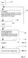
- control device 54 works according to the flow chart of FIG Figure 3 .
- a learning phase is first carried out (step 102) in which the control device 54 determines the current height of the tractor 18 above sea level on the basis of the position signals from the position determination system 62 and / or a relative change in height compared to a starting position at the start of work or when a predetermined reference position is reached on the basis of the signals of the inclination sensor 70 with regard to the inclination in the forward direction and the signals of one or more of the speed sensors 74 and / or of the radar sensor 82 is determined.
- the operator When working in the field, the operator gives specifications for the pressure in the actuator 46, which determines the soil pressure or the working depth of the soil cultivation tool 42, for the pressure of the actuator 52, which determines the soil pressure, at his workplace via the operator input device 68 (or other suitable input means)
- Ground roller 50 determines the pressure or the position of the actuator 34, which determines the sowing depth of the sowing devices 24, for the propulsion speed of the tractor 18, which is controlled by the actuator 84, and for the density of the seed applied, which is controlled by the actuator 86 is controlled.
- the height or change in height and the associated parameters of the actuators 46, 52, 34, 84, 86 are stored in pairs in the memory device 64.
- the setpoint values of the parameters entered by the operator or the actual values of the parameters recorded by means of suitable sensors can be used.
- suitable sensors e.g. 74 and / or 82 for the forward speed
- the offset between the sensors 62, 70 and the soil-engaging components of the tillage combination 18 ie soil cultivation implement 42, soil roller 50 and sowing devices 24
- the offset between the sensors 62, 70 and the soil-engaging components of the tillage combination 18 ie soil cultivation implement 42, soil roller 50 and sowing devices 24
- step 104 the operator can enter in step 104 that the learning phase is ended. If this is not the case, step 102 follows again, otherwise step 106.
- the height areas can be divided into at least two (“low” and “high”), three (“low”, “medium” and “high”) or even more topographical zones. If there is a change in the operator input and at the same time a non-negligible change in the values of the sensor 62 and / or 70, the control device 54 assumes that a boundary between two topographical zones has been crossed, so that a new topographical zone may be created must be, if this has not yet been driven through. The operator inputs are then assigned to the respective topographical zone. In this way, the field is divided into topographical zones while driving on the basis of the values of the sensor 62 and / or 70 and the operator inputs.
- the parameters of the actuators 46, 52, 34, 84, 86 determined in the respective topographical altitude zones can expediently be averaged in order not to allow the data volumes to become too large and to be able to compensate for individual incorrect entries.
- For the five actuators 46, 52, 34, 84, 86, generally different parameters assigned to them are stored.
- step 106 the parameter to be set is then called up from the memory device 64 on the basis of the height recorded in each case and used for the automatic setting of the actuators 46, 52, 34, 84 and 86.
- step 108 it is then queried whether the operator has overridden one or more of the current parameters of the actuators 46, 52, 34, 84 or 86 via the operator input device 68. If this is not the case, step 106 follows again, otherwise step 110, in which the new parameters now entered by the operator are stored in memory device 64 and used to control actuators 46, 52, 34, 84, 86.
- the height-dependent control of the actuators 46, 52, 34, 84, 86 automates the control of the tillage combination 18 in a simple way and the most fundamental agronomic influencing variables that have to be taken into account when setting the tillage combination (namely whether a depression, a hill or a hill) an area in between is being processed).
- the distance between the seeds can be selected to be greater on dry hills than in moist depressions by means of the actuator 86.
- Another actuator could also be used to switch individual sowing units 24 on and off in order to vary the row spacing transversely to the forward direction.
- the forward speed can be selected to be higher on the hills than in the depressions, in which, in turn, more intensive tillage can take place than on the hills.
- the inclination of the tractor 18 in the lateral direction detected with the inclination sensor 70 can also be taken into account and a distinction can be made in steps 102 and 106 as to whether the part of the field currently being worked is horizontal or inclined.
- the tensile force in the drawbar 16 can also be detected by means of a tensile force sensor 76, and conclusions can thus be drawn about the soil properties, which would also be taken into account in steps 102 and 106.
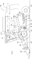
- the Figure 4 shows a self-propelled harvesting machine in the form of a combine harvester 410 with a chassis 412 which is supported on the ground via driven front wheels 414 and steerable rear wheels 416 and is moved by them.
- the wheels 414, 416 are set in rotation by means of drive means (not shown) in order to drive the combine harvester 410 e.g. B. to move over a field to be harvested.
- directional information such as front and rear, relate to the direction of travel V of the combine harvester 410 in the harvesting operation, which is shown in FIG Figure 4 runs to the left.
- a header 418 in the form of a cutting unit is detachably connected to the front end area of the combine harvester 410 in order to harvest crops in the form of grain or other threshable crops from the field during the harvesting operation and to feed it upwards and to the rear through an inclined conveyor assembly 420 to an axial threshing unit 422 .
- the mixture which passes through concaves and grates in the axial threshing mechanism 422 and contains grains and impurities, reaches a cleaning device 426.
- the cleaned grain from the grain tank 50 can be unloaded by an unloading system with a transverse screw 430 and an unloading conveyor 432.
- the systems mentioned are driven by means of an internal combustion engine and checked and controlled by an operator from a driver's cab 434.
- a controller 54 controls (via valves not shown) the position of an actuator 436 for changing the height of the header 418 above the ground, an actuator 438 for adjusting the speed of a fan 440 of the cleaning system 426, and two actuators 442 for adjusting the opening width of sieves 444 of the cleaning system 426 and an actuator 84 for specifying the advance speed of the combine harvester 410.
- Another actuator (not shown) controlled by the controller 54 could specify the height of a reel of the harvesting header 418.
- controller 54 of combine 410 of FIG Figure 4 corresponds to the flow chart of Figure 3 .
- the operator specifies the parameters for the actuators 84, 436, 438 and 442 via the operator input device 68, which together with the altitude (determined via the position determination system 62) and / or the change in altitude (determined via the inclination sensor 62) in the Storage device 64 are stored and retrieved again in step 106 as a function of altitude or altitude change.
- One in the feederhouse 420 positioned plant sensor 446 for detecting the amount of plants picked up can also be connected to the controller 54 and its signals (analogous to the tensile force sensor 76 in the embodiment according to FIGS Figures 1 to 3 ) are taken into account in steps 102 and 106.
- step 106 the parameters of the actuators 84, 436, 438 and 442 are then called up from the memory device 64 as a function of the height or change in height of the combine harvester 410.
- the harvesting process is automatically adapted to the topographical zone in which the combine harvester 410 is currently located.
- the throughput is therefore lower than in more densely overgrown depressions, so that the advance speed in the depressions will be lower than in the heights.
- the cutting height in the depressions will be greater than on heights and the actuator 436 will move the cutting mechanism further up than on heights on which only smaller plants grow.
- the different throughputs which are dependent on the topographical height zone, are also taken into account in the speed of the fan 440 (actuator 438) and in the setting of the opening sizes of the sieves 444 (actuator 442).
Landscapes
- Life Sciences & Earth Sciences (AREA)
- Soil Sciences (AREA)
- Environmental Sciences (AREA)
- Engineering & Computer Science (AREA)
- Mechanical Engineering (AREA)
- Lifting Devices For Agricultural Implements (AREA)
- Control Of Position, Course, Altitude, Or Attitude Of Moving Bodies (AREA)
- Guiding Agricultural Machines (AREA)
Claims (11)
- Machine agricole (10, 410) pourvue d'un système de réglage automatique d'un paramètre de traitement, ledit système comprenant : un dispositif de commande électronique (54), un actionneur (34, 46, 52, 84, 86, 436, 438, 442) actionné par une force extérieure, commandé par le dispositif de commande (54) et destiné à régler au moins un paramètre de traitement de la machine agricole (10, 410), et un capteur (62, 70) relié au dispositif de commande (54) et destiné à détecter la position verticale de la machine agricole (10, 410), caractérisée en ce que le dispositif de commande (54) est conçu, dans une phase d'apprentissage, pour diviser le champ en différentes zones de hauteur topographiques dans lesquelles les plantes qui y poussent ont des propriétés différentes et, dans une phase d'application, pour déduire à partir des signaux du capteur (62, 70) dans quelle zone de hauteur parmi un certain nombre de zones d'un champ se trouve la machine agricole (10, 410) et pour commander l'actionneur (34, 46, 52, 84, 86, 436, 438, 442) en ligne en fonction de la zone de hauteur respective, le dispositif de commande (54) pouvant être utilisé pendant la phase d'apprentissage pour apprendre et mémoriser tout d'abord les relations entre les entrées d'opérateur destinées à commander l'actionneur (34, 46, 52, 84, 86, 436, 438, 442) et la zone topographique respective puis, pendant la phase d'application, pour commander l'actionneur (34, 46, 52, 84, 86, 436, 438, 442) sur la base de la zone de hauteur topographique respective et de l'entrée d'opérateur mémorisée associée et, dans la phase d'apprentissage, le nombre et/ou les dimensions des zones de hauteur topographiques pouvant être déterminés automatiquement dans le dispositif de commande (54) par le dispositif de commande (54) sur la base des entrées d'opérateur en ce que le dispositif de commande (54) est conçu pour reconnaître, sur la base des entrées de l'opérateur qui varient, l'endroit où une limite doit se situer entre les zones topographiques, en ce que le dispositif de commande (54) enregistre automatiquement la fin de la zone topographique précédente et le début d'une nouvelle zone topographique à l'endroit où l'opérateur modifie un paramètre de fonctionnement de l'actionneur (34, 46, 52, 84, 86, 436, 438, 442) et associe les entrées d'opérateur aux zones respectives.
- Machine agricole (10, 410) selon la revendication 1, le dispositif de commande (54) pouvant être utilisé pour recevoir, par le biais d'un dispositif d'entrée (68) dans la phase d'application, des entrées d'un opérateur destinées à modifier les paramètres de fonctionnement de l'actionneur (34, 46, 52, 84, 86, 436, 438, 442), et pour actualiser les entrées d'opérateur apprises et mémorisées en fonction de ces entrées et à partir de là pour les utiliser pour commander l'actionneur (34, 46, 52, 84, 86, 436, 438, 442) .
- Machine agricole (10, 410) selon l'une des revendications 1 et 2, le dispositif de commande (54) étant relié à un capteur de propriétés de sol (76) destiné à détecter des propriétés du sol et/ou à un capteur de propriétés de plantes (446) destiné à détecter des propriétés des plantes, et étant utilisé pour commander l'actionneur (34, 46, 52, 84, 86, 436, 438, 442) en outre sur la base des signaux du capteur de propriétés de sol (76) et/ou du capteur de propriétés de plantes (446).
- Machine agricole (10, 410) selon l'une des revendications précédentes, le capteur (62) destiné à détecter la position verticale de la machine (10, 410) comprenant un capteur de pression d'air et/ou un système de détermination de position par satellite (62) .
- Machine agricole (10) selon l'une des revendications 1 à 4, la machine agricole étant un tracteur (18) pourvu d'un dispositif de traitement (42, 50) monté sur celui-ci ou tiré par celui-ci, et l'actionneur (84) commandant la vitesse du tracteur (18) et/ou la vitesse de rotation d'un arbre de prise de force et/ou la position d'un accouplement réglable auquel le dispositif de traitement (42, 50) est fixé.
- Machine agricole (10) selon l'une des revendications 1 à 5, la machine agricole (10) étant ou comprenant une machine de traitement de sol et l'actionneur (46, 52) commandant la profondeur de travail des outils de traitement de sol (42, 50) de la machine de traitement de sol.
- Machine agricole (10) selon l'une des revendications 1 à 6, la machine agricole (10) étant ou comprenant un semoir pourvu de dispositifs de semis (24) et l'actionneur (34, 86) commandant la profondeur de semis et/ou l'espacement des graines dans la direction vers l'avant et/ou dans la direction latérale.
- Machine agricole (10) selon l'une des revendications 1 à 5, la machine agricole (10) étant ou comprenant une machine de distribution destinée à distribuer des matières telles que des graines, des engrais, des herbicides ou des pesticides et l'actionneur (86) commandant la quantité distribuée par unité de surface.
- Machine agricole (410) selon l'une des revendications 1 à 4, la machine agricole étant une moissonneuse-batteuse (410) et l'actionneur (84, 436, 438, 442) commandant la hauteur de coupe et/ou la hauteur de rabatteur d'une tête de récolte (418) et/ou la vitesse de rotation d'une soufflante de nettoyage (440) et/ou la taille d'ouverture d'un tamis de nettoyage (444) et/ou la vitesse d'avance de la moissonneuse-batteuse (410).
- Machine agricole (10, 410) selon l'une des revendications 1 à 9, le capteur (62, 70) étant en outre conçu pour détecter l'inclinaison de la machine agricole (10, 410) dans la direction d'avance et/ou dans la direction latérale et le dispositif de commande (54) pouvant être utilisé pour déterminer différentes zones d'inclinaison topographiques du champ et pour commander les paramètres de traitement de la machine agricole, en plus de la commande basée sur la zone de hauteur topographique, également sur la base de la zone d'inclinaison topographique respective.
- Procédé de réglage automatique d'un paramètre de traitement d'une machine agricole (10, 410), un dispositif de commande électronique (54) commandant un actionneur (34, 46, 52, 84, 86, 436, 438, 442) actionné par une force extérieure et destiné à régler au moins un paramètre de traitement de la machine agricole (10, 410) et un capteur (62, 70) relié au dispositif de commande (54) détectant la position verticale de la machine agricole (10, 410), caractérisé en ce que le dispositif de commande (54) divise, dans une phase d'apprentissage, le champ en différentes zones de hauteur topographiques dans lesquelles les qui y poussent ont des propriétés différentes et déduit, dans une phase d'application, à partir des signaux du capteur (62, 70), dans quelle zone de hauteur parmi un certain nombre de zones d'un champ se trouve la machine agricole (10, 410) et commande l'actionneur (34, 46, 52, 84, 86, 436, 438, 442) en ligne en fonction de la zone de hauteur respective, le dispositif de commande (54) apprenant et mémorisant, pendant la phase d'apprentissage, tout d'abord les relations entre les entrées d'opérateur destinées à commander l'actionneur (34, 46, 52, 84, 86, 436, 438, 442) et la zone topographique respective puis commandant, pendant la phase d'application, l'actionneur (34, 46, 52, 84, 86, 436, 438, 442) sur la base de la zone de hauteur topographique respective et de l'entrée d'opérateur mémorisée associée et, dans la phase d'apprentissage, le nombre et/ou les dimensions des zones de hauteur topographiques étant déterminés automatiquement dans le dispositif de commande (54) par le dispositif de commande (54) sur la base des entrées d'opérateur en ce que le dispositif de commande (54) reconnaît, sur la base des entrées de l'opérateur qui varient, l'endroit où une limite doit se situer entre les zones topographiques, en ce que le dispositif de commande (54) enregistre automatiquement la fin de la zone topographique précédente et le début d'une nouvelle zone topographique à l'endroit où l'opérateur modifie un paramètre de fonctionnement de l'actionneur (34, 46, 52, 84, 86, 436, 438, 442) et associe les entrées d'opérateur aux zones respectives.
Applications Claiming Priority (1)
| Application Number | Priority Date | Filing Date | Title |
|---|---|---|---|
| DE102012201333A DE102012201333A1 (de) | 2012-01-31 | 2012-01-31 | Landwirtschaftliche Maschine mit einem System zur selbsttätigen Einstellung eines Bearbeitungsparameters und zugehöriges Verfahren |
Publications (3)
| Publication Number | Publication Date |
|---|---|
| EP2622955A1 EP2622955A1 (fr) | 2013-08-07 |
| EP2622955B1 EP2622955B1 (fr) | 2018-11-21 |
| EP2622955B2 true EP2622955B2 (fr) | 2021-08-18 |
Family
ID=47602891
Family Applications (1)
| Application Number | Title | Priority Date | Filing Date |
|---|---|---|---|
| EP12196700.4A Not-in-force EP2622955B2 (fr) | 2012-01-31 | 2012-12-12 | Machine agricole dotée d'un système de réglage automatique d'un paramètre de travail et procédé correspondant |
Country Status (4)
| Country | Link |
|---|---|
| US (1) | US8738244B2 (fr) |
| EP (1) | EP2622955B2 (fr) |
| AU (1) | AU2013200397B2 (fr) |
| DE (1) | DE102012201333A1 (fr) |
Families Citing this family (132)
| Publication number | Priority date | Publication date | Assignee | Title |
|---|---|---|---|---|
| US9169973B2 (en) * | 2012-12-18 | 2015-10-27 | Agco Corporation | Zonal operator presence detection |
| DE102013100793A1 (de) * | 2013-01-28 | 2014-07-31 | Usines Claas France S.A.S. | Kombination aus einem Zugfahrzeug und einer davon gezogenen landwirtschaftlichen Erntemaschine |
| US11212962B2 (en) | 2013-02-20 | 2022-01-04 | Deere & Company | Field condition determination |
| CA2866050C (fr) * | 2013-12-11 | 2019-02-26 | Cnh Industrial Canada, Ltd. | Protection d'actionneur capteur pour appareil agricole |
| DE102014105820A1 (de) * | 2014-04-25 | 2015-10-29 | Usines Claas France S.A.S. | Kombination aus einem Zugfahrzeug und einer davon gezogenen Erntemaschine |
| DE102014106775A1 (de) * | 2014-05-14 | 2015-11-19 | Amazonen-Werke H. Dreyer Gmbh & Co. Kg | Landwirtschaftliche Arbeitsmaschine |
| TR201407381A2 (tr) | 2014-06-25 | 2016-01-21 | Dokuz Eyluel Ueniversitesi Rektoerluegue | Üç eksen hareketli solar enerji kaynaklı tarım otomasyonu. |
| US20160029547A1 (en) * | 2014-07-30 | 2016-02-04 | Deere & Company | Sensing the soil profile behind a soil-engaging implement |
| DE202014103642U1 (de) | 2014-08-06 | 2015-11-09 | Vorwerk & Co. Interholding Gmbh | Gargefäß und Kombination eines Untergefäßes mit einem Gargefäß |
| US9795079B2 (en) | 2014-10-02 | 2017-10-24 | Cnh Industrial Canada, Ltd. | Pneumatic delivery system for application implement using multiple metering devices |
| US9826677B2 (en) | 2014-12-16 | 2017-11-28 | Cnh Industrial Canada, Ltd. | Seed implement incorporating a down pressure sensing and adjustment system |
| US9668399B2 (en) | 2015-03-10 | 2017-06-06 | Andrew R. Gates | Dynamically adaptive soil conditioning system |
| PL3069600T3 (pl) * | 2015-03-20 | 2020-01-31 | Pöttinger Landtechnik Gmbh | Maszyna żniwna |
| DE102015105217A1 (de) * | 2015-04-07 | 2016-10-13 | Claas Saulgau Gmbh | Verfahren zum Betreiben eines landwirtschaftlichen Erntefahrzeugs und Steuerungseinrichtung |
| EP3100601B1 (fr) * | 2015-06-02 | 2020-02-19 | AGCO International GmbH | Détermination de la hauteur d'un récepteur de positionnement pour machines mobiles |
| US9883626B2 (en) * | 2015-10-02 | 2018-02-06 | Deere & Company | Controlling an agricultural vehicle based on sensed inputs |
| US11266056B2 (en) | 2015-10-23 | 2022-03-08 | Deere & Company | System and method for residue detection and implement control |
| CN105766201B (zh) * | 2016-04-12 | 2018-03-02 | 沧州市农林科学院 | 一种苜蓿追施水溶肥设备 |
| DE202016008712U1 (de) * | 2016-09-28 | 2019-02-22 | Amazonen-Werke H. Dreyer Gmbh & Co. Kg | Landwirtschaftliches Fahrzeug |
| US10194574B2 (en) * | 2016-11-18 | 2019-02-05 | Cnh Industrial America Llc | System for adjusting smoothing tools of a harrow according to location |
| US10251327B2 (en) | 2016-11-22 | 2019-04-09 | Cnh Industrial Canada, Ltd. | Agricultural implement hydraulic rephasing unit and method |
| US10589580B2 (en) | 2017-01-31 | 2020-03-17 | Deere & Company | Pin-drop hitch mount assembly with biased pin retainer mechanism |
| US10618362B2 (en) | 2017-01-31 | 2020-04-14 | Deere & Company | Pin-drop hitch mount assembly with alignment features for aligning drawbar and drawbar receiver |
| US10556472B2 (en) | 2017-01-31 | 2020-02-11 | Deere & Company | Pin-drop hitch mount assembly with biased pin retainer mechanism |
| US10618361B2 (en) | 2017-01-31 | 2020-04-14 | Deere & Company | Pin-drop hitch mount assembly with biased pin retainer mechanism |
| DE102017204433A1 (de) * | 2017-03-16 | 2018-09-20 | Zf Friedrichshafen Ag | Verfahren zum Betreiben eines Systems aus einem landwirtschaftlichen Arbeitsfahrzeug und zumindest einem an diesem angeordneten Arbeitsgerät |
| DE102017205293A1 (de) * | 2017-03-29 | 2018-10-04 | Deere & Company | Verfahren und Vorrichtung zur Bekämpfung unerwünschter Lebewesen auf einem Feld |
| DE102017208442A1 (de) * | 2017-05-18 | 2018-11-22 | Deere & Company | Selbstlernende, Korrektureingaben berücksichtigende Anordnung zur selbsttätigen Kontrolle eines Arbeitsparameters einer Erntegutförder- und/oder -bearbeitungseinrichtung |
| DE102017004808B3 (de) * | 2017-05-19 | 2018-09-06 | Baumer Electric Ag | Steuervorrichtung und Verfahren zur Steuerung einer Höhe eines Auslegers eines Fahrzeugs |
| US10481142B2 (en) | 2017-05-25 | 2019-11-19 | Deere & Company | Sensor system for determining soil characteristics |
| US10588259B2 (en) | 2017-07-10 | 2020-03-17 | Cnh Industrial America Llc | Location based chop to swath conversion for riparian buffer zone management |
| US10582655B2 (en) | 2017-08-23 | 2020-03-10 | Cnh Industrial Canada, Ltd. | System and method for spraying fluid onto seeds dispensed from a planter |
| US11140807B2 (en) | 2017-09-07 | 2021-10-12 | Deere & Company | System for optimizing agricultural machine settings |
| US10459443B2 (en) * | 2017-09-22 | 2019-10-29 | Erik Jertberg | Semi-autonomous farm transport vehicle for picked produce |
| PL3499199T3 (pl) | 2017-12-15 | 2022-01-03 | Kistler Holding Ag | Czujnik vim i sposób wytwarzania czujnika vim |
| DE102017011747A1 (de) | 2017-12-19 | 2019-06-19 | Ana-U Gmbh | Bodenbearbeitungssystem |
| US11419261B2 (en) * | 2018-06-25 | 2022-08-23 | Deere & Company | Prescription cover crop seeding with combine |
| DE102018212075A1 (de) * | 2018-07-19 | 2020-01-23 | Deere & Company | Mähdrescher mit einem Schrägförderer mit aktorisch verstellbarer, unterer Umlenkwalze |
| US10757854B2 (en) | 2018-08-27 | 2020-09-01 | Cnh Industrial America Llc | Determining forces exerted on rolling agricultural components based on an applied braking force |
| US10827665B2 (en) * | 2018-09-19 | 2020-11-10 | Deere & Company | Tool height control for ground engaging tools |
| US11957072B2 (en) | 2020-02-06 | 2024-04-16 | Deere & Company | Pre-emergence weed detection and mitigation system |
| US11079725B2 (en) | 2019-04-10 | 2021-08-03 | Deere & Company | Machine control using real-time model |
| US11178818B2 (en) | 2018-10-26 | 2021-11-23 | Deere & Company | Harvesting machine control system with fill level processing based on yield data |
| US11240961B2 (en) | 2018-10-26 | 2022-02-08 | Deere & Company | Controlling a harvesting machine based on a geo-spatial representation indicating where the harvesting machine is likely to reach capacity |
| US11641800B2 (en) | 2020-02-06 | 2023-05-09 | Deere & Company | Agricultural harvesting machine with pre-emergence weed detection and mitigation system |
| US12069978B2 (en) | 2018-10-26 | 2024-08-27 | Deere & Company | Predictive environmental characteristic map generation and control system |
| US11672203B2 (en) | 2018-10-26 | 2023-06-13 | Deere & Company | Predictive map generation and control |
| US11589509B2 (en) | 2018-10-26 | 2023-02-28 | Deere & Company | Predictive machine characteristic map generation and control system |
| US11467605B2 (en) | 2019-04-10 | 2022-10-11 | Deere & Company | Zonal machine control |
| US11653588B2 (en) | 2018-10-26 | 2023-05-23 | Deere & Company | Yield map generation and control system |
| DE102019201914A1 (de) | 2019-02-14 | 2020-08-20 | Zf Friedrichshafen Ag | Trajektoriebestimmung für Landmaschinen unter Verwendung von Rasterkarten |
| DE102019201913A1 (de) | 2019-02-14 | 2020-08-20 | Zf Friedrichshafen Ag | RFID-basierte Bewegungsbegrenzung von Landmaschinen |
| DE102019201915A1 (de) | 2019-02-14 | 2020-08-20 | Zf Friedrichshafen Ag | Steuerung von Landmaschinen basierend auf Kombination aus Abstandsensorik und Kamera |
| US11770988B2 (en) * | 2019-03-06 | 2023-10-03 | Cnh Industrial America Llc | Adjustable closing system for an agricultural implement |
| DE102019108730A1 (de) * | 2019-04-03 | 2020-10-08 | Horsch Leeb Application Systems Gmbh | Technik zur Erzeugung eines Geländeprofils mit einer Landmaschine |
| US11778945B2 (en) | 2019-04-10 | 2023-10-10 | Deere & Company | Machine control using real-time model |
| US11234366B2 (en) | 2019-04-10 | 2022-02-01 | Deere & Company | Image selection for machine control |
| EP3782444A1 (fr) * | 2019-08-22 | 2021-02-24 | Deere & Company | Procédé et sytème de sauvegarde et de rappel des valeurs de réglage d'un véhicule et/ou d'un outil agricole |
| US11219153B2 (en) | 2019-08-29 | 2022-01-11 | Cnh Industrial America Llc | System and method for monitoring shank float |
| US11140803B2 (en) * | 2019-09-16 | 2021-10-12 | Cnh Industrial America Llc | System and method for rotationally driving ground engaging tools of an agricultural implement |
| US11105351B2 (en) | 2019-09-20 | 2021-08-31 | Cnh Industrial America Llc | Agricultural baler with hydraulic flow controller |
| US11665991B2 (en) | 2019-09-24 | 2023-06-06 | Cnh Industrial America Llc | System and method for monitoring the levelness of a multi-wing agricultural implement |
| JP7293070B2 (ja) * | 2019-09-25 | 2023-06-19 | 株式会社クボタ | 散布支援システム |
| WO2021070577A1 (fr) * | 2019-10-11 | 2021-04-15 | 株式会社小松製作所 | Engin de chantier et procédé de commande pour engin de chantier |
| US11470763B2 (en) | 2019-11-07 | 2022-10-18 | Cnh Industrial Canada, Ltd. | System and method for determining subsurface soil layer characteristics based on RADAR and load data |
| US12225846B2 (en) | 2020-02-06 | 2025-02-18 | Deere & Company | Machine control using a predictive map |
| US12329148B2 (en) | 2020-02-06 | 2025-06-17 | Deere & Company | Predictive weed map and material application machine control |
| US12035648B2 (en) | 2020-02-06 | 2024-07-16 | Deere & Company | Predictive weed map generation and control system |
| US11685412B2 (en) * | 2020-03-05 | 2023-06-27 | Caterpillar Paving Products Inc. | Override of autonomous functions of a machine |
| US11477940B2 (en) | 2020-03-26 | 2022-10-25 | Deere & Company | Mobile work machine control based on zone parameter modification |
| US11592822B2 (en) | 2020-10-09 | 2023-02-28 | Deere & Company | Machine control using a predictive map |
| US11849671B2 (en) | 2020-10-09 | 2023-12-26 | Deere & Company | Crop state map generation and control system |
| US11889788B2 (en) | 2020-10-09 | 2024-02-06 | Deere & Company | Predictive biomass map generation and control |
| US11711995B2 (en) | 2020-10-09 | 2023-08-01 | Deere & Company | Machine control using a predictive map |
| US11983009B2 (en) | 2020-10-09 | 2024-05-14 | Deere & Company | Map generation and control system |
| US11474523B2 (en) | 2020-10-09 | 2022-10-18 | Deere & Company | Machine control using a predictive speed map |
| US20220110258A1 (en) | 2020-10-09 | 2022-04-14 | Deere & Company | Map generation and control system |
| US12013245B2 (en) | 2020-10-09 | 2024-06-18 | Deere & Company | Predictive map generation and control system |
| US12178158B2 (en) | 2020-10-09 | 2024-12-31 | Deere & Company | Predictive map generation and control system for an agricultural work machine |
| US11845449B2 (en) | 2020-10-09 | 2023-12-19 | Deere & Company | Map generation and control system |
| US12069986B2 (en) | 2020-10-09 | 2024-08-27 | Deere & Company | Map generation and control system |
| US11849672B2 (en) | 2020-10-09 | 2023-12-26 | Deere & Company | Machine control using a predictive map |
| US11825768B2 (en) | 2020-10-09 | 2023-11-28 | Deere & Company | Machine control using a predictive map |
| US11650587B2 (en) | 2020-10-09 | 2023-05-16 | Deere & Company | Predictive power map generation and control system |
| US11871697B2 (en) | 2020-10-09 | 2024-01-16 | Deere & Company | Crop moisture map generation and control system |
| US11864483B2 (en) | 2020-10-09 | 2024-01-09 | Deere & Company | Predictive map generation and control system |
| US11874669B2 (en) | 2020-10-09 | 2024-01-16 | Deere & Company | Map generation and control system |
| US11727680B2 (en) | 2020-10-09 | 2023-08-15 | Deere & Company | Predictive map generation based on seeding characteristics and control |
| US12419220B2 (en) * | 2020-10-09 | 2025-09-23 | Deere & Company | Predictive map generation and control system |
| US11895948B2 (en) | 2020-10-09 | 2024-02-13 | Deere & Company | Predictive map generation and control based on soil properties |
| US11635765B2 (en) | 2020-10-09 | 2023-04-25 | Deere & Company | Crop state map generation and control system |
| US12422847B2 (en) * | 2020-10-09 | 2025-09-23 | Deere & Company | Predictive agricultural model and map generation |
| US12386354B2 (en) | 2020-10-09 | 2025-08-12 | Deere & Company | Predictive power map generation and control system |
| US11927459B2 (en) | 2020-10-09 | 2024-03-12 | Deere & Company | Machine control using a predictive map |
| US11675354B2 (en) | 2020-10-09 | 2023-06-13 | Deere & Company | Machine control using a predictive map |
| US20220110238A1 (en) | 2020-10-09 | 2022-04-14 | Deere & Company | Machine control using a predictive map |
| US12550802B2 (en) | 2020-10-08 | 2026-02-17 | Deere & Company | Predictive machine characteristic map generation and control system |
| US11946747B2 (en) | 2020-10-09 | 2024-04-02 | Deere & Company | Crop constituent map generation and control system |
| US11844311B2 (en) | 2020-10-09 | 2023-12-19 | Deere & Company | Machine control using a predictive map |
| US11889787B2 (en) | 2020-10-09 | 2024-02-06 | Deere & Company | Predictive speed map generation and control system |
| US12250905B2 (en) | 2020-10-09 | 2025-03-18 | Deere & Company | Machine control using a predictive map |
| US12075769B2 (en) | 2020-12-21 | 2024-09-03 | Deere & Company | Agricultural sprayer with real-time, on-machine target sensor |
| US11832609B2 (en) | 2020-12-21 | 2023-12-05 | Deere & Company | Agricultural sprayer with real-time, on-machine target sensor |
| US11944087B2 (en) | 2020-12-21 | 2024-04-02 | Deere & Company | Agricultural sprayer with real-time, on-machine target sensor |
| WO2022136182A1 (fr) * | 2020-12-23 | 2022-06-30 | Basf Agro Trademarks Gmbh | Procédé pour déterminer un taux d'ensemencement spécifique d'un champ ou d'une zone, la profondeur et le temps pour planter une culture dans un champ agricole sur la base de multiples entrées de données telles que des données de culture, de champ, de rendement, de conditions météorologiques et/ou de sol |
| CN112715112B (zh) * | 2021-01-05 | 2021-11-26 | 广西壮族自治区农业科学院 | 一种具有智能下种控制结构的甘蔗播种机 |
| JP7633413B2 (ja) * | 2021-01-11 | 2025-02-19 | アグトノミー | スマート器具 |
| US12127500B2 (en) | 2021-01-27 | 2024-10-29 | Deere & Company | Machine control using a map with regime zones |
| US20230035002A1 (en) * | 2021-07-27 | 2023-02-02 | Symeo Gmbh | Apparatus and method for particle deposition distribution estimation |
| US12229886B2 (en) | 2021-10-01 | 2025-02-18 | Deere & Company | Historical crop state model, predictive crop state map generation and control system |
| US12213408B2 (en) * | 2021-11-10 | 2025-02-04 | Deere & Company | Combine harvester operation based on windrow data stream |
| US12310286B2 (en) | 2021-12-14 | 2025-05-27 | Deere & Company | Crop constituent sensing |
| US12302791B2 (en) | 2021-12-20 | 2025-05-20 | Deere & Company | Crop constituents, predictive mapping, and agricultural harvester control |
| US12245549B2 (en) | 2022-01-11 | 2025-03-11 | Deere & Company | Predictive response map generation and control system |
| US12520759B2 (en) | 2022-01-26 | 2026-01-13 | Deere & Company | Systems and methods for predicting material dynamics |
| US12082531B2 (en) | 2022-01-26 | 2024-09-10 | Deere & Company | Systems and methods for predicting material dynamics |
| US12295288B2 (en) | 2022-04-05 | 2025-05-13 | Deere &Company | Predictive machine setting map generation and control system |
| US12298767B2 (en) | 2022-04-08 | 2025-05-13 | Deere & Company | Predictive material consumption map and control |
| US12284934B2 (en) | 2022-04-08 | 2025-04-29 | Deere & Company | Systems and methods for predictive tractive characteristics and control |
| US12582035B2 (en) | 2022-04-08 | 2026-03-24 | Deere & Company | Systems and methods for predictive power requirements and control |
| US12358493B2 (en) | 2022-04-08 | 2025-07-15 | Deere & Company | Systems and methods for predictive power requirements and control |
| US12058951B2 (en) | 2022-04-08 | 2024-08-13 | Deere & Company | Predictive nutrient map and control |
| DE102022110628A1 (de) * | 2022-05-02 | 2023-11-02 | Amazonen-Werke H. Dreyer SE & Co. KG | Verfahren zum Steuern der Aushubstellung an einer landwirtschaftlichen Anbaumaschine, Steuersystem und Anbaumaschine |
| JP7801170B2 (ja) * | 2022-05-13 | 2026-01-16 | ヤンマーホールディングス株式会社 | 作業支援方法、作業車両及び作業支援システム |
| US12317768B2 (en) | 2022-06-22 | 2025-06-03 | Christian Kiel | Automatic terrain adjustment system for an agricultural implement |
| DE102022121027A1 (de) * | 2022-08-19 | 2024-02-22 | Amazonen-Werke H. Dreyer SE & Co. KG | Ausbringsystem zum Ausbringen von Dünger und Verfahren zum Ausbringen von Dünger |
| US12364179B2 (en) | 2022-10-31 | 2025-07-22 | Deere & Company | Map based farming for windrower operation |
| US12369507B2 (en) | 2022-10-31 | 2025-07-29 | Deere & Company | Map based farming for windrower operation |
| US20240138284A1 (en) * | 2022-10-31 | 2024-05-02 | Deere & Company | Map based farming for windrower operation |
| US12557724B2 (en) | 2022-10-31 | 2026-02-24 | Deere & Company | Map based farming for windrower operation |
| DE102023135792A1 (de) * | 2023-12-19 | 2025-06-26 | Claas Selbstfahrende Erntemaschinen Gmbh | Selbstfahrender Mähdrescher mit Haspeleingriffseinstellung |
| US20250268137A1 (en) * | 2024-02-26 | 2025-08-28 | Cnh Industrial America Llc | System and method for controlling the operation of an agricultural harvester |
Citations (15)
| Publication number | Priority date | Publication date | Assignee | Title |
|---|---|---|---|---|
| WO1995002318A2 (fr) † | 1993-07-17 | 1995-01-26 | Duerrstein Georg | Procede permettant de travailler des terres exploitables |
| DE19508944A1 (de) † | 1995-03-13 | 1996-09-19 | Claas Ohg | Selbstlenkvorrichtung |
| DE19614916A1 (de) † | 1996-04-16 | 1997-11-06 | Detlef Raupach | Fahrroboter für die automatische Behandlung von Bodenflächen |
| EP0922385A1 (fr) † | 1997-12-10 | 1999-06-16 | Amazonen-Werke H. Dreyer GmbH & Co. KG | Machine agricole pour épandre de la matière, notamment pulvérisateur de champ |
| DE19921996A1 (de) † | 1999-05-12 | 2000-11-16 | Amazonen Werke Dreyer H | Vorrichtung zum Ausbringen von landwirtschaftlichem Material |
| DE10129133A1 (de) † | 2001-06-16 | 2002-12-19 | Deere & Co | Einrichtung zur selbsttätigen Lenkung eines landwirtschaftlichen Arbeitsfahrzeugs |
| US6698368B2 (en) † | 2001-08-31 | 2004-03-02 | Bourgault Industries Ltd. | Zone control for agricultural product application |
| EP1405556A2 (fr) † | 2002-10-06 | 2004-04-07 | Claas Saulgau Gmbh | Faucheuse automoteur à grande largeur de travail |
| EP1692929A1 (fr) † | 2005-02-16 | 2006-08-23 | Amazonen-Werke H. Dreyer GmbH & Co. KG | Procédé de commande et/ou contrôle pour épandeur centrifuge d'engrais |
| DE102005008105A1 (de) † | 2005-02-21 | 2006-08-31 | Amazonen-Werke H. Dreyer Gmbh & Co. Kg | Elektronisches Maschinen-Management-System |
| US20070089390A1 (en) † | 2005-10-25 | 2007-04-26 | Hendrickson Larry L | Crop attribute map input for vehicle guidance |
| DE102006055858A1 (de) † | 2006-11-27 | 2008-05-29 | Carl Zeiss Ag | Verfahren und Anordnung zur Steuerung eines Fahrzeuges |
| WO2008088916A2 (fr) † | 2007-01-18 | 2008-07-24 | Deere & Company | Commande de la position d'un matériel agricole couplé à un véhicule agricole sur la base de données topographiques tridimensionnelles |
| DE112006003007T5 (de) † | 2005-10-21 | 2008-10-16 | Deere & Company, Moline | Systeme und Verfahren zum Vermeiden von Hindernissen |
| WO2012091988A1 (fr) † | 2010-12-29 | 2012-07-05 | Dow Agrosciences Llc | Systèmes et procédés de dérive de pulvérisation |
Family Cites Families (19)
| Publication number | Priority date | Publication date | Assignee | Title |
|---|---|---|---|---|
| EP0282639A3 (fr) | 1987-03-14 | 1989-08-30 | Franz Kirchberger | Procédé et dispositif de commande de machines agricoles en fonction de leur position sur une surface à cultiver |
| DE4016603A1 (de) | 1990-05-23 | 1991-11-28 | Amazonen Werke Dreyer H | Bordcomputersystem fuer landwirtschaftliche maschinen- und geraetekombinationen |
| US5931882A (en) * | 1993-07-29 | 1999-08-03 | Raven Industries | Combination grid recipe and depth control system |
| DE4431824C1 (de) | 1994-09-07 | 1996-05-02 | Claas Ohg | Mähdrescherbetrieb mit Betriebsdatenkataster |
| GB2318651A (en) | 1996-10-23 | 1998-04-29 | New Holland | Integrated vehicle control system |
| US6070673A (en) * | 1996-11-22 | 2000-06-06 | Case Corporation | Location based tractor control |
| US6070539A (en) | 1997-03-21 | 2000-06-06 | Case Corporation | Variable rate agricultural product application implement with multiple inputs and feedback |
| DE19830858A1 (de) * | 1998-07-10 | 2000-01-13 | Claas Selbstfahr Erntemasch | Vorrichtung und Verfahren zur Bestimmung einer virtuellen Position |
| FR2783945B1 (fr) | 1998-09-29 | 2000-12-15 | Pellenc Sa | Procede d'exploitation de donnees agricoles localisees pour optimiser la culture des plantes perennes |
| US6522948B1 (en) * | 2000-08-14 | 2003-02-18 | Flexi-Coil Ltd. | Agricultural product application tracking and control |
| DE10133191A1 (de) | 2001-07-07 | 2003-01-16 | Deere & Co | Landwirtschaftliche Bestellkombination |
| US6810315B2 (en) * | 2001-11-21 | 2004-10-26 | Pgi International, Ltd. | Agricultural vehicle dispenser regulator and method |
| US7184892B1 (en) * | 2003-01-31 | 2007-02-27 | Deere & Company | Method and system of evaluating performance of a crop |
| US8594879B2 (en) * | 2003-03-20 | 2013-11-26 | Agjunction Llc | GNSS guidance and machine control |
| US8639416B2 (en) * | 2003-03-20 | 2014-01-28 | Agjunction Llc | GNSS guidance and machine control |
| US8260499B2 (en) * | 2007-05-01 | 2012-09-04 | Deere & Company | Automatic steering system and method for a work vehicle with feedback gain dependent on a sensed payload |
| US8319165B2 (en) | 2007-07-03 | 2012-11-27 | Holland Kyle H | Variable rate chemical management for agricultural landscapes |
| DE102007049652B4 (de) | 2007-10-11 | 2019-04-25 | Amazonen-Werke H. Dreyer Gmbh & Co. Kg | Verfahren und Vorrichtung zur Steuerung eines Düngerstreuers |
| DE102011050474A1 (de) | 2011-05-19 | 2012-11-22 | Amazonen-Werke H. Dreyer Gmbh & Co.Kg | Landwirtschaftliches Gerät |
-
2012
- 2012-01-31 DE DE102012201333A patent/DE102012201333A1/de not_active Ceased
- 2012-12-12 EP EP12196700.4A patent/EP2622955B2/fr not_active Not-in-force
-
2013
- 2013-01-25 AU AU2013200397A patent/AU2013200397B2/en not_active Ceased
- 2013-01-30 US US13/754,040 patent/US8738244B2/en active Active
Patent Citations (16)
| Publication number | Priority date | Publication date | Assignee | Title |
|---|---|---|---|---|
| WO1995002318A2 (fr) † | 1993-07-17 | 1995-01-26 | Duerrstein Georg | Procede permettant de travailler des terres exploitables |
| DE19508944A1 (de) † | 1995-03-13 | 1996-09-19 | Claas Ohg | Selbstlenkvorrichtung |
| DE19614916A1 (de) † | 1996-04-16 | 1997-11-06 | Detlef Raupach | Fahrroboter für die automatische Behandlung von Bodenflächen |
| EP0922385A1 (fr) † | 1997-12-10 | 1999-06-16 | Amazonen-Werke H. Dreyer GmbH & Co. KG | Machine agricole pour épandre de la matière, notamment pulvérisateur de champ |
| DE19921996A1 (de) † | 1999-05-12 | 2000-11-16 | Amazonen Werke Dreyer H | Vorrichtung zum Ausbringen von landwirtschaftlichem Material |
| DE10129133A1 (de) † | 2001-06-16 | 2002-12-19 | Deere & Co | Einrichtung zur selbsttätigen Lenkung eines landwirtschaftlichen Arbeitsfahrzeugs |
| US6698368B2 (en) † | 2001-08-31 | 2004-03-02 | Bourgault Industries Ltd. | Zone control for agricultural product application |
| EP1405556A2 (fr) † | 2002-10-06 | 2004-04-07 | Claas Saulgau Gmbh | Faucheuse automoteur à grande largeur de travail |
| EP1692929A1 (fr) † | 2005-02-16 | 2006-08-23 | Amazonen-Werke H. Dreyer GmbH & Co. KG | Procédé de commande et/ou contrôle pour épandeur centrifuge d'engrais |
| DE102005008105A1 (de) † | 2005-02-21 | 2006-08-31 | Amazonen-Werke H. Dreyer Gmbh & Co. Kg | Elektronisches Maschinen-Management-System |
| DE112006003007T5 (de) † | 2005-10-21 | 2008-10-16 | Deere & Company, Moline | Systeme und Verfahren zum Vermeiden von Hindernissen |
| US20070089390A1 (en) † | 2005-10-25 | 2007-04-26 | Hendrickson Larry L | Crop attribute map input for vehicle guidance |
| DE102006055858A1 (de) † | 2006-11-27 | 2008-05-29 | Carl Zeiss Ag | Verfahren und Anordnung zur Steuerung eines Fahrzeuges |
| WO2008088916A2 (fr) † | 2007-01-18 | 2008-07-24 | Deere & Company | Commande de la position d'un matériel agricole couplé à un véhicule agricole sur la base de données topographiques tridimensionnelles |
| WO2012091988A1 (fr) † | 2010-12-29 | 2012-07-05 | Dow Agrosciences Llc | Systèmes et procédés de dérive de pulvérisation |
| EP2658370A1 (fr) † | 2010-12-29 | 2013-11-06 | Dow AgroSciences LLC | Systèmes et procédés de dérive de pulvérisation |
Also Published As
| Publication number | Publication date |
|---|---|
| EP2622955A1 (fr) | 2013-08-07 |
| AU2013200397B2 (en) | 2014-11-13 |
| DE102012201333A1 (de) | 2013-08-01 |
| US8738244B2 (en) | 2014-05-27 |
| US20130197767A1 (en) | 2013-08-01 |
| EP2622955B1 (fr) | 2018-11-21 |
| AU2013200397A1 (en) | 2013-08-15 |
Similar Documents
| Publication | Publication Date | Title |
|---|---|---|
| EP2622955B2 (fr) | Machine agricole dotée d'un système de réglage automatique d'un paramètre de travail et procédé correspondant | |
| EP3278645B1 (fr) | Procédé d'optimisation d'un paramètre de travail d'une machine d'extraction de matériel agricole sur un champ et machine correspondante | |
| EP3141096B1 (fr) | Procede d'epandage de particules de semences ou de plantes dans un champ et machine correspondante | |
| EP3300571B1 (fr) | Dispositif de calcul optimisé de masses de remplissage pour une machine destinée à l'application du matériel agricole et d'établissement optimisé du plan de parcours | |
| EP2636292B1 (fr) | Agencement et procédé destiné à l'ensemencement de graines | |
| EP1273215B1 (fr) | Machine combinée pour le travail agricole | |
| EP3338524B1 (fr) | Semoir monograine agricole et procédé | |
| DE102019134184A1 (de) | Landwirtschaftliche Maschine, vorzugsweise zur Bodenbearbeitung und/oder Aussaat und Verfahren zum Steuern und/oder Regeln der Arbeitstiefe einer Werkzeugeinheit | |
| EP1402766A1 (fr) | Procédé de commande et de régulation de machines agricoles de travail et/ou de distribution | |
| DE112013003233T5 (de) | Gewichtsverteilungssystem für Samenpflanzer und Produktapplikatoren | |
| EP3756433B1 (fr) | Système de commande d'un outil de travail raccordé à un véhicule | |
| DE102020117911A1 (de) | Verfahren zum Pflanzenanbau in einem regelmäßigen Muster mit standortangepasster Variation der Pflanzendichte | |
| EP4260702A1 (fr) | Machine de distribution agricole dotée d'une tringlerie de distribution et procédé de commande de l'orientation de la tringlerie de distribution | |
| EP4260700A1 (fr) | Machine de distribution agricole dotée d'une tringlerie de distribution et procédé de commande de l'orientation de la tringlerie de distribution | |
| DE4002172C1 (en) | Agricultural implement for preparing soil - has self propelled vehicle with platform which has movable working arm | |
| DE102016104641A1 (de) | Verfahren zur Bewirtschaftung von Nutzflächen | |
| DE102020110367A1 (de) | System für eine landwirtschaftliche Arbeitsmaschine, Verfahren zum Ermitteln einer Position von Arbeitselementen sowie landwirtschaftliche Arbeitsmaschine | |
| EP1513390B1 (fr) | Dispositif et procede de plantation en lignes | |
| DE102022108555A1 (de) | Steuersystem und Verfahren zum Verändern der Lage von an einer landwirtschaftlichen Maschine angebrachten Arbeitsaggregaten sowie landwirtschaftliche Maschine | |
| DE102021124958A1 (de) | Verfahren und Benutzerschnittstellenvorrichtung zum Durchführen der Ausbringung von Agrargut auf einem Feld | |
| DE102019203645A1 (de) | Anordnung zur automatischen Kontrolle der Position eines Werkzeugs | |
| DE102021126258A1 (de) | Landwirtschaftliche Verteilmaschine, vorzugsweise eine Feldspritze oder ein pneumatischer Düngerstreuer | |
| DE102019202852A1 (de) | System und Verfahren zur Steuerung eines Arbeitsgeräts | |
| DE102019119290A1 (de) | Verfahren zur Erstellung einer Stoppelhöhenkarte |
Legal Events
| Date | Code | Title | Description |
|---|---|---|---|
| PUAI | Public reference made under article 153(3) epc to a published international application that has entered the european phase |
Free format text: ORIGINAL CODE: 0009012 |
|
| AK | Designated contracting states |
Kind code of ref document: A1 Designated state(s): AL AT BE BG CH CY CZ DE DK EE ES FI FR GB GR HR HU IE IS IT LI LT LU LV MC MK MT NL NO PL PT RO RS SE SI SK SM TR |
|
| AX | Request for extension of the european patent |
Extension state: BA ME |
|
| 17P | Request for examination filed |
Effective date: 20140207 |
|
| RBV | Designated contracting states (corrected) |
Designated state(s): AL AT BE BG CH CY CZ DE DK EE ES FI FR GB GR HR HU IE IS IT LI LT LU LV MC MK MT NL NO PL PT RO RS SE SI SK SM TR |
|
| STAA | Information on the status of an ep patent application or granted ep patent |
Free format text: STATUS: EXAMINATION IS IN PROGRESS |
|
| 17Q | First examination report despatched |
Effective date: 20180117 |
|
| GRAP | Despatch of communication of intention to grant a patent |
Free format text: ORIGINAL CODE: EPIDOSNIGR1 |
|
| STAA | Information on the status of an ep patent application or granted ep patent |
Free format text: STATUS: GRANT OF PATENT IS INTENDED |
|
| INTG | Intention to grant announced |
Effective date: 20180614 |
|
| GRAS | Grant fee paid |
Free format text: ORIGINAL CODE: EPIDOSNIGR3 |
|
| GRAA | (expected) grant |
Free format text: ORIGINAL CODE: 0009210 |
|
| STAA | Information on the status of an ep patent application or granted ep patent |
Free format text: STATUS: THE PATENT HAS BEEN GRANTED |
|
| AK | Designated contracting states |
Kind code of ref document: B1 Designated state(s): AL AT BE BG CH CY CZ DE DK EE ES FI FR GB GR HR HU IE IS IT LI LT LU LV MC MK MT NL NO PL PT RO RS SE SI SK SM TR |
|
| REG | Reference to a national code |
Ref country code: CH Ref legal event code: EP |
|
| REG | Reference to a national code |
Ref country code: IE Ref legal event code: FG4D Free format text: LANGUAGE OF EP DOCUMENT: GERMAN |
|
| REG | Reference to a national code |
Ref country code: DE Ref legal event code: R096 Ref document number: 502012013853 Country of ref document: DE |
|
| REG | Reference to a national code |
Ref country code: AT Ref legal event code: REF Ref document number: 1066406 Country of ref document: AT Kind code of ref document: T Effective date: 20181215 |
|
| REG | Reference to a national code |
Ref country code: NL Ref legal event code: MP Effective date: 20181121 |
|
| PG25 | Lapsed in a contracting state [announced via postgrant information from national office to epo] |
Ref country code: NO Free format text: LAPSE BECAUSE OF FAILURE TO SUBMIT A TRANSLATION OF THE DESCRIPTION OR TO PAY THE FEE WITHIN THE PRESCRIBED TIME-LIMIT Effective date: 20190221 Ref country code: BG Free format text: LAPSE BECAUSE OF FAILURE TO SUBMIT A TRANSLATION OF THE DESCRIPTION OR TO PAY THE FEE WITHIN THE PRESCRIBED TIME-LIMIT Effective date: 20190221 Ref country code: FI Free format text: LAPSE BECAUSE OF FAILURE TO SUBMIT A TRANSLATION OF THE DESCRIPTION OR TO PAY THE FEE WITHIN THE PRESCRIBED TIME-LIMIT Effective date: 20181121 Ref country code: LT Free format text: LAPSE BECAUSE OF FAILURE TO SUBMIT A TRANSLATION OF THE DESCRIPTION OR TO PAY THE FEE WITHIN THE PRESCRIBED TIME-LIMIT Effective date: 20181121 Ref country code: LV Free format text: LAPSE BECAUSE OF FAILURE TO SUBMIT A TRANSLATION OF THE DESCRIPTION OR TO PAY THE FEE WITHIN THE PRESCRIBED TIME-LIMIT Effective date: 20181121 Ref country code: HR Free format text: LAPSE BECAUSE OF FAILURE TO SUBMIT A TRANSLATION OF THE DESCRIPTION OR TO PAY THE FEE WITHIN THE PRESCRIBED TIME-LIMIT Effective date: 20181121 Ref country code: ES Free format text: LAPSE BECAUSE OF FAILURE TO SUBMIT A TRANSLATION OF THE DESCRIPTION OR TO PAY THE FEE WITHIN THE PRESCRIBED TIME-LIMIT Effective date: 20181121 Ref country code: IS Free format text: LAPSE BECAUSE OF FAILURE TO SUBMIT A TRANSLATION OF THE DESCRIPTION OR TO PAY THE FEE WITHIN THE PRESCRIBED TIME-LIMIT Effective date: 20190321 |
|
| PG25 | Lapsed in a contracting state [announced via postgrant information from national office to epo] |
Ref country code: PT Free format text: LAPSE BECAUSE OF FAILURE TO SUBMIT A TRANSLATION OF THE DESCRIPTION OR TO PAY THE FEE WITHIN THE PRESCRIBED TIME-LIMIT Effective date: 20190321 Ref country code: GR Free format text: LAPSE BECAUSE OF FAILURE TO SUBMIT A TRANSLATION OF THE DESCRIPTION OR TO PAY THE FEE WITHIN THE PRESCRIBED TIME-LIMIT Effective date: 20190222 Ref country code: SE Free format text: LAPSE BECAUSE OF FAILURE TO SUBMIT A TRANSLATION OF THE DESCRIPTION OR TO PAY THE FEE WITHIN THE PRESCRIBED TIME-LIMIT Effective date: 20181121 Ref country code: RS Free format text: LAPSE BECAUSE OF FAILURE TO SUBMIT A TRANSLATION OF THE DESCRIPTION OR TO PAY THE FEE WITHIN THE PRESCRIBED TIME-LIMIT Effective date: 20181121 Ref country code: NL Free format text: LAPSE BECAUSE OF FAILURE TO SUBMIT A TRANSLATION OF THE DESCRIPTION OR TO PAY THE FEE WITHIN THE PRESCRIBED TIME-LIMIT Effective date: 20181121 Ref country code: AL Free format text: LAPSE BECAUSE OF FAILURE TO SUBMIT A TRANSLATION OF THE DESCRIPTION OR TO PAY THE FEE WITHIN THE PRESCRIBED TIME-LIMIT Effective date: 20181121 |
|
| PG25 | Lapsed in a contracting state [announced via postgrant information from national office to epo] |
Ref country code: IT Free format text: LAPSE BECAUSE OF FAILURE TO SUBMIT A TRANSLATION OF THE DESCRIPTION OR TO PAY THE FEE WITHIN THE PRESCRIBED TIME-LIMIT Effective date: 20181121 Ref country code: DK Free format text: LAPSE BECAUSE OF FAILURE TO SUBMIT A TRANSLATION OF THE DESCRIPTION OR TO PAY THE FEE WITHIN THE PRESCRIBED TIME-LIMIT Effective date: 20181121 Ref country code: CZ Free format text: LAPSE BECAUSE OF FAILURE TO SUBMIT A TRANSLATION OF THE DESCRIPTION OR TO PAY THE FEE WITHIN THE PRESCRIBED TIME-LIMIT Effective date: 20181121 Ref country code: PL Free format text: LAPSE BECAUSE OF FAILURE TO SUBMIT A TRANSLATION OF THE DESCRIPTION OR TO PAY THE FEE WITHIN THE PRESCRIBED TIME-LIMIT Effective date: 20181121 |
|
| REG | Reference to a national code |
Ref country code: CH Ref legal event code: PL |
|
| REG | Reference to a national code |
Ref country code: DE Ref legal event code: R026 Ref document number: 502012013853 Country of ref document: DE |
|
| PLBI | Opposition filed |
Free format text: ORIGINAL CODE: 0009260 |
|
| PG25 | Lapsed in a contracting state [announced via postgrant information from national office to epo] |
Ref country code: MC Free format text: LAPSE BECAUSE OF FAILURE TO SUBMIT A TRANSLATION OF THE DESCRIPTION OR TO PAY THE FEE WITHIN THE PRESCRIBED TIME-LIMIT Effective date: 20181121 Ref country code: SK Free format text: LAPSE BECAUSE OF FAILURE TO SUBMIT A TRANSLATION OF THE DESCRIPTION OR TO PAY THE FEE WITHIN THE PRESCRIBED TIME-LIMIT Effective date: 20181121 Ref country code: LU Free format text: LAPSE BECAUSE OF NON-PAYMENT OF DUE FEES Effective date: 20181212 Ref country code: SM Free format text: LAPSE BECAUSE OF FAILURE TO SUBMIT A TRANSLATION OF THE DESCRIPTION OR TO PAY THE FEE WITHIN THE PRESCRIBED TIME-LIMIT Effective date: 20181121 Ref country code: EE Free format text: LAPSE BECAUSE OF FAILURE TO SUBMIT A TRANSLATION OF THE DESCRIPTION OR TO PAY THE FEE WITHIN THE PRESCRIBED TIME-LIMIT Effective date: 20181121 Ref country code: RO Free format text: LAPSE BECAUSE OF FAILURE TO SUBMIT A TRANSLATION OF THE DESCRIPTION OR TO PAY THE FEE WITHIN THE PRESCRIBED TIME-LIMIT Effective date: 20181121 |
|
| PLAX | Notice of opposition and request to file observation + time limit sent |
Free format text: ORIGINAL CODE: EPIDOSNOBS2 |
|
| REG | Reference to a national code |
Ref country code: IE Ref legal event code: MM4A |
|
| 26 | Opposition filed |
Opponent name: KVERNELAND A/S Effective date: 20190821 Opponent name: AMAZONEN-WERKE H. DREYER GMBH & CO. KG Effective date: 20190821 |
|
| REG | Reference to a national code |
Ref country code: BE Ref legal event code: MM Effective date: 20181231 |
|
| PLBB | Reply of patent proprietor to notice(s) of opposition received |
Free format text: ORIGINAL CODE: EPIDOSNOBS3 |
|
| PG25 | Lapsed in a contracting state [announced via postgrant information from national office to epo] |
Ref country code: SI Free format text: LAPSE BECAUSE OF FAILURE TO SUBMIT A TRANSLATION OF THE DESCRIPTION OR TO PAY THE FEE WITHIN THE PRESCRIBED TIME-LIMIT Effective date: 20181121 Ref country code: IE Free format text: LAPSE BECAUSE OF NON-PAYMENT OF DUE FEES Effective date: 20181212 |
|
| PG25 | Lapsed in a contracting state [announced via postgrant information from national office to epo] |
Ref country code: BE Free format text: LAPSE BECAUSE OF NON-PAYMENT OF DUE FEES Effective date: 20181231 |
|
| PG25 | Lapsed in a contracting state [announced via postgrant information from national office to epo] |
Ref country code: LI Free format text: LAPSE BECAUSE OF NON-PAYMENT OF DUE FEES Effective date: 20181231 Ref country code: CH Free format text: LAPSE BECAUSE OF NON-PAYMENT OF DUE FEES Effective date: 20181231 |
|
| PG25 | Lapsed in a contracting state [announced via postgrant information from national office to epo] |
Ref country code: MT Free format text: LAPSE BECAUSE OF FAILURE TO SUBMIT A TRANSLATION OF THE DESCRIPTION OR TO PAY THE FEE WITHIN THE PRESCRIBED TIME-LIMIT Effective date: 20181121 |
|
| REG | Reference to a national code |
Ref country code: AT Ref legal event code: MM01 Ref document number: 1066406 Country of ref document: AT Kind code of ref document: T Effective date: 20181212 |
|
| PG25 | Lapsed in a contracting state [announced via postgrant information from national office to epo] |
Ref country code: TR Free format text: LAPSE BECAUSE OF FAILURE TO SUBMIT A TRANSLATION OF THE DESCRIPTION OR TO PAY THE FEE WITHIN THE PRESCRIBED TIME-LIMIT Effective date: 20181121 |
|
| PG25 | Lapsed in a contracting state [announced via postgrant information from national office to epo] |
Ref country code: AT Free format text: LAPSE BECAUSE OF NON-PAYMENT OF DUE FEES Effective date: 20181212 |
|
| PG25 | Lapsed in a contracting state [announced via postgrant information from national office to epo] |
Ref country code: CY Free format text: LAPSE BECAUSE OF FAILURE TO SUBMIT A TRANSLATION OF THE DESCRIPTION OR TO PAY THE FEE WITHIN THE PRESCRIBED TIME-LIMIT Effective date: 20181121 Ref country code: HU Free format text: LAPSE BECAUSE OF FAILURE TO SUBMIT A TRANSLATION OF THE DESCRIPTION OR TO PAY THE FEE WITHIN THE PRESCRIBED TIME-LIMIT; INVALID AB INITIO Effective date: 20121212 Ref country code: MK Free format text: LAPSE BECAUSE OF NON-PAYMENT OF DUE FEES Effective date: 20181121 |
|
| RIC2 | Information provided on ipc code assigned after grant |
Ipc: A01C 21/00 20060101ALI20210226BHEP Ipc: A01D 41/127 20060101ALI20210226BHEP Ipc: A01B 79/00 20060101AFI20210226BHEP |
|
| PUAH | Patent maintained in amended form |
Free format text: ORIGINAL CODE: 0009272 |
|
| STAA | Information on the status of an ep patent application or granted ep patent |
Free format text: STATUS: PATENT MAINTAINED AS AMENDED |
|
| 27A | Patent maintained in amended form |
Effective date: 20210818 |
|
| AK | Designated contracting states |
Kind code of ref document: B2 Designated state(s): AL AT BE BG CH CY CZ DE DK EE ES FI FR GB GR HR HU IE IS IT LI LT LU LV MC MK MT NL NO PL PT RO RS SE SI SK SM TR |
|
| REG | Reference to a national code |
Ref country code: DE Ref legal event code: R102 Ref document number: 502012013853 Country of ref document: DE |
|
| PGFP | Annual fee paid to national office [announced via postgrant information from national office to epo] |
Ref country code: GB Payment date: 20231227 Year of fee payment: 12 |
|
| PGFP | Annual fee paid to national office [announced via postgrant information from national office to epo] |
Ref country code: FR Payment date: 20231227 Year of fee payment: 12 Ref country code: DE Payment date: 20231121 Year of fee payment: 12 |
|
| REG | Reference to a national code |
Ref country code: DE Ref legal event code: R119 Ref document number: 502012013853 Country of ref document: DE |
|
| GBPC | Gb: european patent ceased through non-payment of renewal fee |
Effective date: 20241212 |
|
| PG25 | Lapsed in a contracting state [announced via postgrant information from national office to epo] |
Ref country code: DE Free format text: LAPSE BECAUSE OF NON-PAYMENT OF DUE FEES Effective date: 20250701 |
|
| PG25 | Lapsed in a contracting state [announced via postgrant information from national office to epo] |
Ref country code: GB Free format text: LAPSE BECAUSE OF NON-PAYMENT OF DUE FEES Effective date: 20241212 |
|
| PG25 | Lapsed in a contracting state [announced via postgrant information from national office to epo] |
Ref country code: FR Free format text: LAPSE BECAUSE OF NON-PAYMENT OF DUE FEES Effective date: 20241231 |