EP2623302A1 - Processus de mise en sachet sous vide assistée par agitation et appareil correspondant - Google Patents
Processus de mise en sachet sous vide assistée par agitation et appareil correspondant Download PDFInfo
- Publication number
- EP2623302A1 EP2623302A1 EP12153242.8A EP12153242A EP2623302A1 EP 2623302 A1 EP2623302 A1 EP 2623302A1 EP 12153242 A EP12153242 A EP 12153242A EP 2623302 A1 EP2623302 A1 EP 2623302A1
- Authority
- EP
- European Patent Office
- Prior art keywords
- vacuum
- mattress
- bladders
- source
- bladder
- Prior art date
- Legal status (The legal status is an assumption and is not a legal conclusion. Google has not performed a legal analysis and makes no representation as to the accuracy of the status listed.)
- Withdrawn
Links
- 238000000034 method Methods 0.000 title claims abstract description 25
- 238000013019 agitation Methods 0.000 title 1
- 239000000835 fiber Substances 0.000 claims abstract description 10
- 238000007596 consolidation process Methods 0.000 claims description 24
- 238000010438 heat treatment Methods 0.000 claims description 19
- 239000002131 composite material Substances 0.000 claims description 14
- 239000012530 fluid Substances 0.000 claims description 8
- 238000004519 manufacturing process Methods 0.000 claims description 8
- 238000004891 communication Methods 0.000 claims description 7
- 239000000463 material Substances 0.000 claims description 7
- 230000003213 activating effect Effects 0.000 claims description 4
- 229920002430 Fibre-reinforced plastic Polymers 0.000 claims 1
- 239000011151 fibre-reinforced plastic Substances 0.000 claims 1
- 229920005989 resin Polymers 0.000 description 5
- 239000011347 resin Substances 0.000 description 5
- 238000009826 distribution Methods 0.000 description 3
- 239000002184 metal Substances 0.000 description 3
- 229910052751 metal Inorganic materials 0.000 description 3
- 230000003014 reinforcing effect Effects 0.000 description 3
- 239000004696 Poly ether ether ketone Substances 0.000 description 2
- 229910000831 Steel Inorganic materials 0.000 description 2
- JUPQTSLXMOCDHR-UHFFFAOYSA-N benzene-1,4-diol;bis(4-fluorophenyl)methanone Chemical compound OC1=CC=C(O)C=C1.C1=CC(F)=CC=C1C(=O)C1=CC=C(F)C=C1 JUPQTSLXMOCDHR-UHFFFAOYSA-N 0.000 description 2
- 238000006073 displacement reaction Methods 0.000 description 2
- 230000000694 effects Effects 0.000 description 2
- 239000003365 glass fiber Substances 0.000 description 2
- 239000011159 matrix material Substances 0.000 description 2
- 229920002530 polyetherether ketone Polymers 0.000 description 2
- 238000012545 processing Methods 0.000 description 2
- 230000003068 static effect Effects 0.000 description 2
- 239000010959 steel Substances 0.000 description 2
- 229920001169 thermoplastic Polymers 0.000 description 2
- 239000004634 thermosetting polymer Substances 0.000 description 2
- 238000013519 translation Methods 0.000 description 2
- 241000531908 Aramides Species 0.000 description 1
- 229920002799 BoPET Polymers 0.000 description 1
- OKTJSMMVPCPJKN-UHFFFAOYSA-N Carbon Chemical compound [C] OKTJSMMVPCPJKN-UHFFFAOYSA-N 0.000 description 1
- 239000004593 Epoxy Substances 0.000 description 1
- 239000005041 Mylar™ Substances 0.000 description 1
- 239000004952 Polyamide Substances 0.000 description 1
- 229920002873 Polyethylenimine Polymers 0.000 description 1
- 239000005030 aluminium foil Substances 0.000 description 1
- -1 and the like Polymers 0.000 description 1
- 229920003235 aromatic polyamide Polymers 0.000 description 1
- 230000015572 biosynthetic process Effects 0.000 description 1
- 229910052799 carbon Inorganic materials 0.000 description 1
- 239000004020 conductor Substances 0.000 description 1
- 238000001816 cooling Methods 0.000 description 1
- 230000001419 dependent effect Effects 0.000 description 1
- 239000000428 dust Substances 0.000 description 1
- 238000005265 energy consumption Methods 0.000 description 1
- 239000004744 fabric Substances 0.000 description 1
- 230000006698 induction Effects 0.000 description 1
- 239000012212 insulator Substances 0.000 description 1
- 238000005457 optimization Methods 0.000 description 1
- 229920001652 poly(etherketoneketone) Polymers 0.000 description 1
- 229920002647 polyamide Polymers 0.000 description 1
- 229920000728 polyester Polymers 0.000 description 1
- 229920006267 polyester film Polymers 0.000 description 1
- 229920001601 polyetherimide Polymers 0.000 description 1
- 239000005020 polyethylene terephthalate Substances 0.000 description 1
- 229920000139 polyethylene terephthalate Polymers 0.000 description 1
- 229920001721 polyimide Polymers 0.000 description 1
- 229920001296 polysiloxane Polymers 0.000 description 1
- 239000002243 precursor Substances 0.000 description 1
- 238000002360 preparation method Methods 0.000 description 1
- 230000005855 radiation Effects 0.000 description 1
- 238000007789 sealing Methods 0.000 description 1
- 229920001187 thermosetting polymer Polymers 0.000 description 1
- 239000004416 thermosoftening plastic Substances 0.000 description 1
Images

Classifications
-
- B—PERFORMING OPERATIONS; TRANSPORTING
- B29—WORKING OF PLASTICS; WORKING OF SUBSTANCES IN A PLASTIC STATE IN GENERAL
- B29C—SHAPING OR JOINING OF PLASTICS; SHAPING OF MATERIAL IN A PLASTIC STATE, NOT OTHERWISE PROVIDED FOR; AFTER-TREATMENT OF THE SHAPED PRODUCTS, e.g. REPAIRING
- B29C70/00—Shaping composites, i.e. plastics material comprising reinforcements, fillers or preformed parts, e.g. inserts
- B29C70/04—Shaping composites, i.e. plastics material comprising reinforcements, fillers or preformed parts, e.g. inserts comprising reinforcements only, e.g. self-reinforcing plastics
- B29C70/28—Shaping operations therefor
- B29C70/40—Shaping or impregnating by compression not applied
- B29C70/42—Shaping or impregnating by compression not applied for producing articles of definite length, i.e. discrete articles
- B29C70/44—Shaping or impregnating by compression not applied for producing articles of definite length, i.e. discrete articles using isostatic pressure, e.g. pressure difference-moulding, vacuum bag-moulding, autoclave-moulding or expanding rubber-moulding
-
- B—PERFORMING OPERATIONS; TRANSPORTING
- B30—PRESSES
- B30B—PRESSES IN GENERAL
- B30B5/00—Presses characterised by the use of pressing means other than those mentioned in the preceding groups
- B30B5/02—Presses characterised by the use of pressing means other than those mentioned in the preceding groups wherein the pressing means is in the form of a flexible element, e.g. diaphragm, urged by fluid pressure
-
- B—PERFORMING OPERATIONS; TRANSPORTING
- B32—LAYERED PRODUCTS
- B32B—LAYERED PRODUCTS, i.e. PRODUCTS BUILT-UP OF STRATA OF FLAT OR NON-FLAT, e.g. CELLULAR OR HONEYCOMB, FORM
- B32B37/00—Methods or apparatus for laminating, e.g. by curing or by ultrasonic bonding
- B32B37/10—Methods or apparatus for laminating, e.g. by curing or by ultrasonic bonding characterised by the pressing technique, e.g. using action of vacuum or fluid pressure
- B32B37/1009—Methods or apparatus for laminating, e.g. by curing or by ultrasonic bonding characterised by the pressing technique, e.g. using action of vacuum or fluid pressure using vacuum and fluid pressure
-
- B—PERFORMING OPERATIONS; TRANSPORTING
- B29—WORKING OF PLASTICS; WORKING OF SUBSTANCES IN A PLASTIC STATE IN GENERAL
- B29K—INDEXING SCHEME ASSOCIATED WITH SUBCLASSES B29B, B29C OR B29D, RELATING TO MOULDING MATERIALS OR TO MATERIALS FOR MOULDS, REINFORCEMENTS, FILLERS OR PREFORMED PARTS, e.g. INSERTS
- B29K2105/00—Condition, form or state of moulded material or of the material to be shaped
- B29K2105/06—Condition, form or state of moulded material or of the material to be shaped containing reinforcements, fillers or inserts
- B29K2105/08—Condition, form or state of moulded material or of the material to be shaped containing reinforcements, fillers or inserts of continuous length, e.g. cords, rovings, mats, fabrics, strands or yarns
- B29K2105/0872—Prepregs
-
- B—PERFORMING OPERATIONS; TRANSPORTING
- B32—LAYERED PRODUCTS
- B32B—LAYERED PRODUCTS, i.e. PRODUCTS BUILT-UP OF STRATA OF FLAT OR NON-FLAT, e.g. CELLULAR OR HONEYCOMB, FORM
- B32B2305/00—Condition, form or state of the layers or laminate
- B32B2305/07—Parts immersed or impregnated in a matrix
- B32B2305/076—Prepregs
-
- B—PERFORMING OPERATIONS; TRANSPORTING
- B32—LAYERED PRODUCTS
- B32B—LAYERED PRODUCTS, i.e. PRODUCTS BUILT-UP OF STRATA OF FLAT OR NON-FLAT, e.g. CELLULAR OR HONEYCOMB, FORM
- B32B2309/00—Parameters for the laminating or treatment process; Apparatus details
- B32B2309/02—Temperature
-
- B—PERFORMING OPERATIONS; TRANSPORTING
- B32—LAYERED PRODUCTS
- B32B—LAYERED PRODUCTS, i.e. PRODUCTS BUILT-UP OF STRATA OF FLAT OR NON-FLAT, e.g. CELLULAR OR HONEYCOMB, FORM
- B32B2309/00—Parameters for the laminating or treatment process; Apparatus details
- B32B2309/12—Pressure
Definitions
- the present invention relates to a vacuum bagging process for consolidating high performance pre-impregnated fibre reinforced composite laminates.
- it concerns a consolidation process allowing the production of high performance composites requiring no autoclave.
- An apparatus for carrying such process is also described.
- High performance composite parts can be manufactured by stacking a number of pre-impregnated plies --commonly called prepregs-- consisting of reinforcing fibres, usually oriented, impregnated with a thermoplastic polymer or a thermoset resin precursor which is not or only partially cured. Such stacks are enclosed into a vacuum bag provided with at least one vacuum port for evacuating the air contained therein. Temperature and pressure are then applied to the vacuum bag in order to first lower the viscosity of the resin, drive the flow of the resin to consolidate the individual plies to form a laminate and, for thermoset resins, cure the resin.
- prepregs-- consisting of reinforcing fibres, usually oriented, impregnated with a thermoplastic polymer or a thermoset resin precursor which is not or only partially cured.
- Such stacks are enclosed into a vacuum bag provided with at least one vacuum port for evacuating the air contained therein. Temperature and pressure are then applied to the vacuum bag in order to first lower the vis
- Autoclaves are massive and expensive apparatuses available only in a limited number of production companies and requiring considerable time and energy to heat and pressurize the whole inner volume thereof to the processing temperature and pressure. Furthermore, the size of a composite part manufactured by autoclave is limited to the size of the autoclave. All these elements render autoclave forming a very expensive process and limit the use of prepregs to high performance applications with limited production volumes, typically in aerospace.
- the present invention proposes a solution for consolidating prepreg laminates enclosed in a vacuum bag without the need of an autoclave, yet yielding similar consolidation levels of the finished composite parts in a much shorter time and consuming considerably less energy than henceforth achieved.
- the present invention concerns a process for consolidating a fibre reinforced laminate comprising the following steps:
- each bladder be intermittently inflated and deflated at least twice, and even more times, during the consolidation process.
- each bladder is not required to be inflated to a pressure higher than 10 bar.
- a pressure of not more than 7 bar, preferably not more than 5 bar, most preferably not more than 2 bar suffices to fully consolidate a composite laminate.
- the pressurized zone of the mattress formed by the pressurized bladders applies a pressure onto a first portion of the vacuum bag remote from the at least one vacuum port and moves towards said vacuum port(s), so as to literally drive the air towards the vacuum port(s).
- the pressurized zone can move from the first portion of the vacuum bag towards said vacuum port forming a pressurized line which moves in the direction of the vacuum ports.
- the pressurized line sweeps at least twice over the surface of the vacuum bag.
- the pressurized zone forms a closed loop pressurized line starting from a central point of the mattress and advancing radially towards the periphery of the mattress.
- the vacuum bag preferably comprises several vacuum ports arranged around the periphery thereof.
- the present invention also concerns a kit of parts for the consolidation of a fibre reinforced laminate comprising
- the gap between the front and back moulds, when in operating position is such that the vacuum bag filled with a laminate to be consolidated and the mattress stacked thereon with deflated bladders fit snuggly between the front and back moulds.
- the heating means may, for example, be integrated in the front and/or back mould.
- said control means comprise a valve system, which is preferably controlled by a CPU, wherein each bladder is in fluid communication with, on the one hand, the pressure source and, on the other hand, with the vacuum source, each communication controlled by a corresponding valve.
- a valve system which is preferably controlled by a CPU, wherein each bladder is in fluid communication with, on the one hand, the pressure source and, on the other hand, with the vacuum source, each communication controlled by a corresponding valve.
- each bladder extends in a first direction along the whole length of the mattress, and such bladders are disposed side by side over the whole length of the mattress along a second direction transverse to the first direction over the whole width of the mattress; the first and second directions defining the planes over which extend the top and bottom main surfaces of the mattress.
- This geometry permits to arrange all the connections to the pressure and vacuum sources on the side of the mattress, the tubes thus running laterally out of the gap formed between the front and back moulds to the pressure and vacuum sources.
- bladders are disposed side by side over the whole length of the mattress along a first direction and along a second direction transverse to the first direction, thus forming a tiled structure.
- the bladders may form rows of substantially straight lines like a chessboard or, alternatively, may be arranged in a staggered pattern.
- tubes in the second, back mould a first end of each tube being connectable to a source of pressure or of vacuum and the second end of each tube emerging out of the face of the second, back mould in contact with the mattress, said second ends being connectable and located at positions corresponding to ports provided on each bladder.
- the inner volume of the vacuum bag can be defined by two sheets sealed around the whole perimeter thereof, but for the vacuum ports.
- the layup is generally enclosed in the vacuum bag prior to laying the bag containing the layup onto the first main surface of the front mould.
- the layup is first laid onto the front mould and a sheet is laid over the layup and sealed to the first surface of the front mould.
- a mattress formed by at least two inflatable bladders, each connected to a source of vacuum and to a source of pressure can thus be advantageously used for dislodging and displacing air bubbles entrapped in a fibre reinforced multiply laminate upon consolidation thereof.
- the kit of parts described above offers an alternative to autoclaves for the manufacturing of composite parts offering considerable advantages over the latter.
- the equipment is substantially cheaper than an autoclave and can be afforded by a larger number of manufacturing companies, thus increasing the offer. Because of its low price, several such apparatuses of different sizes may be available in a single workshop, thus allowing the optimization of the size of the equipment to the dimensions of the parts to be consolidated.
- each bladder can be inflated / deflated very rapidly, unlike an autoclave requiring time for the pressure to build up in the whole inner volume thereof.
- kit of parts of the present invention may be used for the manufacturing of composite parts in the fields usually using autoclave forming, such as aeronautics, space, and satellite industries, but also in fields generally reluctant to use prepregs because of the cost of the parts, such as in naval and even automotive industries.
- the process of the present invention has in common with autoclave forming all the steps involving the preparation of a layup (3) made of stacked plies (3a) of pre-impregnated fibre reinforced resin, enclosing it into a sealed vacuum bag (4) provided with at least one vacuum port, and connecting said port to at least one vacuum port to a source of vacuum (10a) for evacuating the air present in the bag.
- a sealed vacuum bag (4) provided with at least one vacuum port, and connecting said port to at least one vacuum port to a source of vacuum (10a) for evacuating the air present in the bag.
- any prepreg can be used, comprising a combination of any type of reinforcing fibres, such as carbon fibres, glass fibres, aramide fibres, and the like, with any type of polymeric matrix, be it thermoplastic such as PEEK, PEKK, PEI, PA, PET, and the like, or thermoset such as epoxy, polyester, and the like.
- the fibres may be arranged in any configuration most suitable for a given application: unidirectional, any 0-45-90° stacking sequence, woven, braided, and the like.
- any vacuum bag available on the market can be used, as long as it supports the consolidation temperature which is mostly determined by the matrix used.
- the vacuum bag (4) must define an inner volume suitable for containing a layup (3) made of different plies of prepreg material.
- the inner volume of the vacuum bag (4) can be defined by two sheets sealed around the whole perimeter thereof, but for the vacuum ports.
- the layup is generally enclosed in the vacuum bag prior to laying the bag containing the layup onto the first main surface of the front mould.
- This embodiment can be advantageous to prevent entrapment of dust on the layup surface, as the vacuum bag can be sealed in a separate, clean room.
- the inner volume of the vacuum bag can be defined by a sheet sealed with sealing means (4s) over the whole perimeter thereof to the first main surface of the front mould.
- the layup is first laid onto the front mould and a sheet is laid over the layup and sealed to the first surface of the front mould.
- this operation must be carried out in the workshop where the tool is located.
- Having the layup in direct contact with the first main face of the front mould permits a resultant surface quality of a composite laminate generally superior to the former embodiment, wherein a sheet of the vacuum bag (4) is interposed between the layup (3) and the front mould first main face (1 a), as it can be difficult to avoid the formation of folds in such sheet.
- the number and distribution of vacuum ports can also be varied at will.
- the vacuum bag is to be laid into. It comprises a tool comprising a first, front mould (1a) defining a first main face of the laminate and a second, movable, back mould (1 b) which, in operating position, is separated from the first, front mould by a gap.
- the mould should be such as to maintain the gap dimensions substantially constant during the consolidation process, when bladders are being pressurized and deflated,
- a metal frame can be used to ensure the stiffness of the structure, on which are coupled the front and back moulds (1a, 1b).
- the frame can advantageously be hinged such that the back mould can be moved from an open position to its operating position defining a gap between the two mould parts.
- Any variation and functional feature for simplifying the handling of the front and back moulds can be implemented in the present apparatus without departing from the scope of the invention.
- the gist of the invention is the use of a mattress (2) made of several individually inflatable bladders (2a-2e) arranged in a side by side configuration, wherein each bladder is individually connected to a source of pressurized gas (11) and to a source of vacuum (10b).
- the dimensions of the mattress must be such that the whole area of the layup (3) enclosed in the vacuum bag (4) is covered by the mattress when laid on top of the vacuum bag.
- Each bladder may be connected to a first pipe (12p) coupled with a valve to a source of pressurized gas and a second pipe (12v) coupled with a valve to a source of vacuum.
- one pipe (12) only is connected to each bladder and is coupled to a three-way valve (1 3), with a first connecting line (12p) coupled to a source of pressurized gas and a second connecting line (12v) coupled to a source of vacuum.
- Connecting lines (12p) and (12v) are advantageously connected to two distinct chambers of a manifold, each chamber being fluidly coupled to the source of pressurized gas (11) and of vacuum (10b), respectively (cf. Figure 1(a) &(b)).
- the source of vacuum (10b) used to deflate the bladders can be the same source (10a) used to evacuate gas from the vacuum bag as the inner volume of the latter can be connected to the manifold linked to vacuum pump (10b) via a tube (12b) provided with a valve (12b).
- the source of vacuum (10b) used to deflate the bladders can be the same source (10a) used to evacuate gas from the vacuum bag as the inner volume of the latter can be connected to the manifold linked to vacuum pump (10b) via a tube (12b) provided with a valve (12b).
- it can be a different source.
- Pumps are usually used as the sources of both pressurized gas and vacuum.
- a source of compressed air can be used instead of a pump or compressor as source of pressurized gas.
- the mattress (2) is sandwiched between the vacuum bag (4) containing the layup (3) and the back mould (1 b) when in operating position.
- the front mould supports one main surface of the vacuum bag (4): the opposite main surface of the vacuum bag contacts the mattress (2), which is itself in contact with the back mould (1b).
- the gap defined by the front and back moulds when in operating position should be such that the vacuum bag (4) containing the layup (3) and the mattress (2) with deflated bladders (2a-2e) snuggly fit between the front and back moulds.
- the vacuum bag (4) is evacuated by activating the source of vacuum (10a), usually a vacuum pump.
- the temperature of the layup (3) is raised to the consolidation temperature. Heating of the layup is achieved by activating heating means.
- Heating means can be electrical or fluid heaters arranged in the front and/or back moulds. Since the layup (3) is separated from the back mould by the mattress, which acts as a thermal insulator, any heating means arranged in the back mould have a limited efficacy. It is therefore preferred that most of the heating be provided by the front mould, which contacts the vacuum bag directly.
- a radiation reflecting sheet, like an aluminium foil can be provided between the vacuum bag and the mattress to reflect back part of the heat reaching the mattress.
- a flexible heating sheet can be provided between the vacuum bag and the mattress to heat the back surface of the layup.
- a flexible heating sheet is comparable with a heating blanket, comprising a support sheet which must be flexible, and comprising electrical wires embedded therein, through which current is circulated to produce heat by the Joule effect.
- induction coils can be embedded in the front and back moulds, and a sheet of highly conductive material, like steel can be provided contacting each main surface of the vacuum bag. Heat can thus be induced very locally. If a sheet of the vacuum bag contacts the front surface of the vacuum bag as illustrated in Figure 1(a) , it should be smooth, so that a good surface quality can be achieved in the front surface of the consolidated laminate.
- the sheet contacting the back surface of the vacuum bag needs be very flexible, to transmit the pressure variations of the bladders to the layup.
- a metal fabric such as e.g., knitted steel wires, can be used to ensure maximum flexibility and drapeability.
- the front surface of the laminate and of the vacuum bag are understood here as being the surface contacting the front mould.
- the back surface of the laminate or the vacuum bag is understood as the surface facing the back mould, and contacting the mattress.
- At least a first bladder (2a) of the mattress (2) is inflated, while at the same time a second bladder (2b) of the mattress is deflated with vacuum.
- each bladder is intermittently inflated and deflated at least twice during the consolidation process.
- a pressurized zone applying a pressure onto the layup can be defined at one moment in time by the bladders being inflated at said time.
- This moving pressurized zone can be used to literally drive any gas entrapped in the vacuum bag towards a vacuum port.
- the deflating of the bladders not only defines the shape and displacement rate of the pressurized zone, but also contributes to dislodging any air bubble trapped between fibres or between plies. Indeed, as gas is being pulled out of a bladder, the portion of vacuum bag in contact with said bladder is sucked up momentarily, thus creating a local vibration able to detach any clinging gas bubble in the laminate. Not wishing to be bound by any theory, it is believed that this mechanism combined with the sudden rise of pressure in a bladder creates a hammer effect of high efficacy for the evacuation of any gas entrapped in the layup.
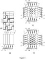
- Figure 2 shows three possible embodiments of bladder geometries and arrangements.
- Figure 2(a) illustrates a first bladder configuration, wherein each bladder extends in a first direction along the whole length of the mattress, and said bladders are disposed side by side over the whole length of the mattress along a second direction transverse to the first direction over the whole width of the mattress.
- the bladder (2a) is deflated and the adjacent bladder (2b) to the right is inflated. This movement dislodges gas bubbles trapped in the layup and pushes them in the right direction.
- the pressurized zone moves one incremental step further to the right, by deflating bladder (2b) and inflating bladder (2c).
- the bladder (2d) is inflated to continue the right movement of the first pressure "wave", and a second pressure "wave” is initiated by inflating again bladder (2a), to further dislodge any clinging gas bubble.
- Figure 2(b) &(c) illustrate two alternative embodiments, wherein several bladders (2a-2e) are disposed side by side over the whole length of the mattress along a first direction and along a second direction transverse to the first direction over the whole width of the mattress.
- the bladders form rows of substantially straight lines in both directions, like a chessboard.
- the bladders can be arranged in a staggered pattern as illustrated in Figure 2(c) .
- Any other geometry and arrangement of bladders is possible depending inter alia on the actual geometry of the part to be consolidated.
- the bladders can be concentric.
- Such mattress is most advantageously used with a vacuum bag provided with vacuum ports distributed around the perimeter thereof. Waves of pressurized zones can be generated to propagate radially from the centre of the mattress towards the perimeter thereof, thus dislodging and driving gas bubbles radially out towards the vacuum ports of the vacuum bag.
- the tubes (12) linking bladders not having an access to the perimeter of the mattress, as the central bladders illustrated in Figure 2(b) &(c) or the inner bladders in an assembly of concentric bladders, to a source of pressurized gas and of vacuum must be connected to a wall thereof which is on a main surface of the mattress, preferably the back surface, as illustrated by double circles (12) in Figure 2(b) &(c). Since the back surface of the mattress applies a substantial pressure onto the back mould where a bladder is inflated, it is preferred that tubes (12) be accommodated in the second, back mould (1 b); a first end of each tube being connectable to a three way valve (13) in fluid communication with a source of pressurized gas (11) and of vacuum (10b).
- each tube emerges out of the face of the second, back mould (1b) in contact with the mattress (2), at positions corresponding to the positions of the ports provided on each bladder (2a-2e).
- any bladder configuration can be used in the present process, without any hindrance between the tubes (12) and the tool front and back moulds (1 a, 1 b).
- each connecting line is advantageously controlled by a central processing unit (CPU).
- the CPU controls each three way valve (13) corresponding to each bladder, to bring them in fluid connection with a source of pressurized gas (11) or a source of vacuum at different moments in time, following a pre-established pattern.
- each tube is provided with a valve controlled similarly by a CPU (not represented in the Figures).
- the bladders may be inflated to a pressure of up to 10 bar; generally not more than 7 bar pressure is required. In most cases, a lower pressure is sufficient to yield a fully consolidated laminate. It has been observed that laminates with similar mechanical properties were obtained with the present process using pressures substantially lower than the ones used in autoclave forming. Not wishing to be bound by any theory, it is believed that this can be explained by the dynamic form of pressure application used in the present process which helps to dislodge clinging gas bubbles and driving them towards a vacuum port, compared with a static form of pressure applied in autoclaves, which does not contribute to dislodging and moving away clinging gas bubbles, but merely to compressing them. For this reason, in many applications, fully consolidated laminates can be obtained with inflating pressures of the bladders of not more than 5 bar, even not more than 2 or 3 bar.
- the bladders must be made of a material which is flexible enough to clearly define a pressurized zone upon inflating and deflating thereof.
- the material must of course be impervious to the pressurized gas used to inflate the bladders, and should be resistant to both inflating pressure and consolidation temperature.
- High temperature resistant silicones readily available on the market can be used for the bladders.
- PEEK films or polyimide films can be used instead.
- the bladder walls may be reinforced or lined with reinforcing fibres, such as glass fibres. Metal sheets can also be used.
- Table 1 compares a number of properties of the present process with the ones of autoclave forming. Table 1: properties comparison between the present process and autoclave forming.
Landscapes
- Physics & Mathematics (AREA)
- Fluid Mechanics (AREA)
- Engineering & Computer Science (AREA)
- Mechanical Engineering (AREA)
- Chemical & Material Sciences (AREA)
- Composite Materials (AREA)
- Casting Or Compression Moulding Of Plastics Or The Like (AREA)
- Moulding By Coating Moulds (AREA)
Priority Applications (2)
| Application Number | Priority Date | Filing Date | Title |
|---|---|---|---|
| EP12153242.8A EP2623302A1 (fr) | 2012-01-31 | 2012-01-31 | Processus de mise en sachet sous vide assistée par agitation et appareil correspondant |
| PCT/EP2013/051785 WO2013113749A1 (fr) | 2012-01-31 | 2013-01-30 | Procédé de mise en poche sous vide assisté par agitation et appareil correspondant |
Applications Claiming Priority (1)
| Application Number | Priority Date | Filing Date | Title |
|---|---|---|---|
| EP12153242.8A EP2623302A1 (fr) | 2012-01-31 | 2012-01-31 | Processus de mise en sachet sous vide assistée par agitation et appareil correspondant |
Publications (1)
| Publication Number | Publication Date |
|---|---|
| EP2623302A1 true EP2623302A1 (fr) | 2013-08-07 |
Family
ID=47605579
Family Applications (1)
| Application Number | Title | Priority Date | Filing Date |
|---|---|---|---|
| EP12153242.8A Withdrawn EP2623302A1 (fr) | 2012-01-31 | 2012-01-31 | Processus de mise en sachet sous vide assistée par agitation et appareil correspondant |
Country Status (2)
| Country | Link |
|---|---|
| EP (1) | EP2623302A1 (fr) |
| WO (1) | WO2013113749A1 (fr) |
Cited By (14)
| Publication number | Priority date | Publication date | Assignee | Title |
|---|---|---|---|---|
| EP3042747A1 (fr) * | 2015-01-12 | 2016-07-13 | Airbus Operations GmbH | Outil de formage et procédé de formation d'un produit semi-fini comprenant des fibres de renforcement et appareil de formation |
| CN106239787A (zh) * | 2015-06-08 | 2016-12-21 | 西门子公司 | 用于叶片制造的混合实心-可充气心轴 |
| CN108568975A (zh) * | 2017-03-13 | 2018-09-25 | 波音公司 | 用于复合部件的囊状物设备、囊状物系统及相关方法 |
| GB2582629A (en) * | 2019-03-28 | 2020-09-30 | Airbus Operations Ltd | A forming tool |
| EP3851264A1 (fr) * | 2020-01-16 | 2021-07-21 | The Boeing Company | Vessie multi-chambre conformable pour l'outillage de pièces composites |
| US20220016812A1 (en) * | 2018-12-14 | 2022-01-20 | Safran | Curing mold for manufacturing a turbomachine component made of composite material from a preform and method for manufacturing a component by means of such a mold |
| EP4230389A1 (fr) * | 2022-02-07 | 2023-08-23 | The Boeing Company | Collecteur à raccordement rapide pour distribution de matériau fluide à un accessoire de formation de pièce et systèmes et procédés associés |
| EP4275872A1 (fr) * | 2022-05-09 | 2023-11-15 | The Boeing Company | Collecteurs rotatifs et systèmes et procédés associés pour ensacher sous vide de grandes structures composites |
| US20240010357A1 (en) * | 2022-07-05 | 2024-01-11 | The Boeing Company | Systems and methods for assembling stiffened composite structures |
| US20240009894A1 (en) * | 2022-07-05 | 2024-01-11 | The Boeing Company | Bladder vent plugs for composite-manufacturing bladders and systems and methods for assembling stiffened composite structures |
| US20250018663A1 (en) * | 2023-07-14 | 2025-01-16 | The Boeing Company | Curing tool assemblies, methods and systems for composite manufacturing |
| EP4606544A1 (fr) * | 2024-02-23 | 2025-08-27 | The Boeing Company | Formage composite |
| DE102024105808A1 (de) * | 2024-02-29 | 2025-09-04 | Airbus Gmbh | System und Verfahren zum Aushärten eines geklebten Strukturbauteils sowie geklebtes Strukturbauteil |
| US12434450B2 (en) | 2023-12-15 | 2025-10-07 | The Boeing Company | Bladder vent plugs for composite manufacturing and related methods and systems |
Citations (3)
| Publication number | Priority date | Publication date | Assignee | Title |
|---|---|---|---|---|
| US5820894A (en) * | 1995-10-06 | 1998-10-13 | Mcdonnell Douglas Corporation | Method and apparatus for consolidating a workpiece at elevated temperature |
| WO2000054951A1 (fr) * | 1999-03-18 | 2000-09-21 | Stewart David H | Procede et appareil de fabrication de structures moulees par moulage sous pression zone |
| WO2008059286A1 (fr) * | 2006-11-14 | 2008-05-22 | Airbus Uk Limited | Procédé et appareil pour commander la géométrie d'un composant composite |
-
2012
- 2012-01-31 EP EP12153242.8A patent/EP2623302A1/fr not_active Withdrawn
-
2013
- 2013-01-30 WO PCT/EP2013/051785 patent/WO2013113749A1/fr not_active Ceased
Patent Citations (3)
| Publication number | Priority date | Publication date | Assignee | Title |
|---|---|---|---|---|
| US5820894A (en) * | 1995-10-06 | 1998-10-13 | Mcdonnell Douglas Corporation | Method and apparatus for consolidating a workpiece at elevated temperature |
| WO2000054951A1 (fr) * | 1999-03-18 | 2000-09-21 | Stewart David H | Procede et appareil de fabrication de structures moulees par moulage sous pression zone |
| WO2008059286A1 (fr) * | 2006-11-14 | 2008-05-22 | Airbus Uk Limited | Procédé et appareil pour commander la géométrie d'un composant composite |
Cited By (30)
| Publication number | Priority date | Publication date | Assignee | Title |
|---|---|---|---|---|
| CN105773996B (zh) * | 2015-01-12 | 2018-10-30 | 空中客车作业有限公司 | 成形包括增强纤维的半成品的成形工具和方法及成形装置 |
| US20160200015A1 (en) * | 2015-01-12 | 2016-07-14 | Airbus Operations Gmbh | Forming tool and method for forming a semi-finished product comprising reinforcement fibers and forming apparatus |
| CN105773996A (zh) * | 2015-01-12 | 2016-07-20 | 空中客车作业有限公司 | 成形包括增强纤维的半成品的成形工具和方法及成形装置 |
| EP3042747A1 (fr) * | 2015-01-12 | 2016-07-13 | Airbus Operations GmbH | Outil de formage et procédé de formation d'un produit semi-fini comprenant des fibres de renforcement et appareil de formation |
| US10894344B2 (en) | 2015-01-12 | 2021-01-19 | Airbus Operations Gmbh | Forming tool and method for forming a semi-finished product comprising reinforcement fibers and forming apparatus |
| CN106239787A (zh) * | 2015-06-08 | 2016-12-21 | 西门子公司 | 用于叶片制造的混合实心-可充气心轴 |
| CN106239787B (zh) * | 2015-06-08 | 2019-02-12 | 西门子公司 | 用于叶片制造的混合实心-可充气心轴 |
| CN108568975B (zh) * | 2017-03-13 | 2022-07-26 | 波音公司 | 用于复合部件的囊状物设备、囊状物系统及相关方法 |
| US10889073B2 (en) | 2017-03-13 | 2021-01-12 | The Boeing Company | Controllable multi-celled bladders for composites |
| EP3378634A1 (fr) * | 2017-03-13 | 2018-09-26 | The Boeing Company | Vessies multicellulaires pouvant être commandées pour composites |
| CN108568975A (zh) * | 2017-03-13 | 2018-09-25 | 波音公司 | 用于复合部件的囊状物设备、囊状物系统及相关方法 |
| US11787132B2 (en) | 2017-03-13 | 2023-10-17 | The Boeing Company | Controllable multi-celled bladders for composites |
| JP2018149799A (ja) * | 2017-03-13 | 2018-09-27 | ザ・ボーイング・カンパニーThe Boeing Company | 複合材のための制御可能なマルチセルのブラダー |
| US12030267B2 (en) * | 2018-12-14 | 2024-07-09 | Safran | Curing mold for manufacturing a turbomachine component made of composite material from a preform and method for manufacturing a component by means of such a mold |
| US20220016812A1 (en) * | 2018-12-14 | 2022-01-20 | Safran | Curing mold for manufacturing a turbomachine component made of composite material from a preform and method for manufacturing a component by means of such a mold |
| GB2582629A (en) * | 2019-03-28 | 2020-09-30 | Airbus Operations Ltd | A forming tool |
| EP3851264A1 (fr) * | 2020-01-16 | 2021-07-21 | The Boeing Company | Vessie multi-chambre conformable pour l'outillage de pièces composites |
| US11559954B2 (en) | 2020-01-16 | 2023-01-24 | The Boeing Company | Multi-chamber conformable bladder for composite part tooling |
| EP4230389A1 (fr) * | 2022-02-07 | 2023-08-23 | The Boeing Company | Collecteur à raccordement rapide pour distribution de matériau fluide à un accessoire de formation de pièce et systèmes et procédés associés |
| US12379059B2 (en) | 2022-02-07 | 2025-08-05 | The Boeing Company | Quick connect manifold for flowable material delivery to a part-forming fixture and associated systems and methods |
| EP4275872A1 (fr) * | 2022-05-09 | 2023-11-15 | The Boeing Company | Collecteurs rotatifs et systèmes et procédés associés pour ensacher sous vide de grandes structures composites |
| US12030262B2 (en) | 2022-05-09 | 2024-07-09 | The Boeing Company | Rotating manifolds and associated systems and methods for vacuum bagging large composite structures |
| US20240009894A1 (en) * | 2022-07-05 | 2024-01-11 | The Boeing Company | Bladder vent plugs for composite-manufacturing bladders and systems and methods for assembling stiffened composite structures |
| US20240010357A1 (en) * | 2022-07-05 | 2024-01-11 | The Boeing Company | Systems and methods for assembling stiffened composite structures |
| US12404039B2 (en) * | 2022-07-05 | 2025-09-02 | The Boeing Company | Systems and methods for assembling stiffened composite structures |
| US12539647B2 (en) * | 2022-07-05 | 2026-02-03 | The Boeing Company | Bladder vent plugs for composite-manufacturing bladders and systems and methods for assembling stiffened composite structures |
| US20250018663A1 (en) * | 2023-07-14 | 2025-01-16 | The Boeing Company | Curing tool assemblies, methods and systems for composite manufacturing |
| US12434450B2 (en) | 2023-12-15 | 2025-10-07 | The Boeing Company | Bladder vent plugs for composite manufacturing and related methods and systems |
| EP4606544A1 (fr) * | 2024-02-23 | 2025-08-27 | The Boeing Company | Formage composite |
| DE102024105808A1 (de) * | 2024-02-29 | 2025-09-04 | Airbus Gmbh | System und Verfahren zum Aushärten eines geklebten Strukturbauteils sowie geklebtes Strukturbauteil |
Also Published As
| Publication number | Publication date |
|---|---|
| WO2013113749A1 (fr) | 2013-08-08 |
Similar Documents
| Publication | Publication Date | Title |
|---|---|---|
| EP2623302A1 (fr) | Processus de mise en sachet sous vide assistée par agitation et appareil correspondant | |
| US6149844A (en) | Method of manufacturing composites | |
| EP2162275B1 (fr) | Dispositif et procédé de traitement d'une structure de composé fibreux | |
| EP3378634B1 (fr) | Vessies multicellulaires pouvant être commandées pour composites | |
| JP5702773B2 (ja) | 金型を使う成形品の製造方法および金型装置 | |
| EP0805746B1 (fr) | Procede de fabrication ameliore concernant les materiaux composites | |
| KR101033476B1 (ko) | 프리프레그 절곡 성형장치 및 그 성형방법 | |
| JP5278790B2 (ja) | 繊維強化樹脂複合材料の製造方法および製造装置 | |
| EP2842711B1 (fr) | Appareil et procédé de production d'un composant d'aéronef en matériau composite | |
| US9421717B2 (en) | Manufacturing a composite | |
| CN102712142A (zh) | 复合材料零件的双真空固化处理 | |
| JP2009542483A (ja) | 複合部品の製造方法 | |
| JP7444567B2 (ja) | 複合構造体を製造するためのシステム及び方法 | |
| WO2011043253A1 (fr) | Procédé et appareil pour produire une matière plastique renforcée par des fibres | |
| EP3915750B1 (fr) | Système et procédé de durcissement de composites thermodurcissables | |
| US20150273809A1 (en) | Apparatuses and methods for efficient sealing of vacuum bag seams | |
| JP5020241B2 (ja) | 航空機用サンドイッチ部品をエネルギー効率よく硬化するプレス装置 | |
| US20130099427A1 (en) | Method and device for producing a composite molded part from fiber-reinforced plastic | |
| EP3628475B1 (fr) | Système et procédé de fabrication de structures composites | |
| JP7444568B2 (ja) | 複合構造体を製造するためのシステム及び方法 | |
| EP3628476B1 (fr) | Système et procédé de fabrication de structures composites | |
| JP5854430B2 (ja) | Frp製造装置およびfrp製造方法 | |
| EP4000885B1 (fr) | Procédé de traitement d'une structure composite | |
| US11938689B2 (en) | Apparatus and method for processing a composite structure | |
| CN106739012A (zh) | 一种复合材料成型平台 |
Legal Events
| Date | Code | Title | Description |
|---|---|---|---|
| PUAI | Public reference made under article 153(3) epc to a published international application that has entered the european phase |
Free format text: ORIGINAL CODE: 0009012 |
|
| AK | Designated contracting states |
Kind code of ref document: A1 Designated state(s): AL AT BE BG CH CY CZ DE DK EE ES FI FR GB GR HR HU IE IS IT LI LT LU LV MC MK MT NL NO PL PT RO RS SE SI SK SM TR |
|
| AX | Request for extension of the european patent |
Extension state: BA ME |
|
| STAA | Information on the status of an ep patent application or granted ep patent |
Free format text: STATUS: THE APPLICATION IS DEEMED TO BE WITHDRAWN |
|
| 18D | Application deemed to be withdrawn |
Effective date: 20140208 |