EP2623441B1 - Dispositif de stockage pour récipients et procédé de stockage de récipients - Google Patents
Dispositif de stockage pour récipients et procédé de stockage de récipients Download PDFInfo
- Publication number
- EP2623441B1 EP2623441B1 EP13166352.8A EP13166352A EP2623441B1 EP 2623441 B1 EP2623441 B1 EP 2623441B1 EP 13166352 A EP13166352 A EP 13166352A EP 2623441 B1 EP2623441 B1 EP 2623441B1
- Authority
- EP
- European Patent Office
- Prior art keywords
- belt
- module
- storage
- transfer
- containers
- Prior art date
- Legal status (The legal status is an assumption and is not a legal conclusion. Google has not performed a legal analysis and makes no representation as to the accuracy of the status listed.)
- Active
Links
Images





Classifications
-
- B—PERFORMING OPERATIONS; TRANSPORTING
- B65—CONVEYING; PACKING; STORING; HANDLING THIN OR FILAMENTARY MATERIAL
- B65G—TRANSPORT OR STORAGE DEVICES, e.g. CONVEYORS FOR LOADING OR TIPPING, SHOP CONVEYOR SYSTEMS OR PNEUMATIC TUBE CONVEYORS
- B65G1/00—Storing articles, individually or in orderly arrangement, in warehouses or magazines
-
- B—PERFORMING OPERATIONS; TRANSPORTING
- B65—CONVEYING; PACKING; STORING; HANDLING THIN OR FILAMENTARY MATERIAL
- B65G—TRANSPORT OR STORAGE DEVICES, e.g. CONVEYORS FOR LOADING OR TIPPING, SHOP CONVEYOR SYSTEMS OR PNEUMATIC TUBE CONVEYORS
- B65G47/00—Article or material-handling devices associated with conveyors; Methods employing such devices
- B65G47/34—Devices for discharging articles or materials from conveyor
- B65G47/46—Devices for discharging articles or materials from conveyor and distributing, e.g. automatically, to desired points
- B65G47/51—Devices for discharging articles or materials from conveyor and distributing, e.g. automatically, to desired points according to unprogrammed signals, e.g. influenced by supply situation at destination
- B65G47/5104—Devices for discharging articles or materials from conveyor and distributing, e.g. automatically, to desired points according to unprogrammed signals, e.g. influenced by supply situation at destination for articles
- B65G47/5109—Devices for discharging articles or materials from conveyor and distributing, e.g. automatically, to desired points according to unprogrammed signals, e.g. influenced by supply situation at destination for articles first In - First Out systems: FIFO
- B65G47/5113—Devices for discharging articles or materials from conveyor and distributing, e.g. automatically, to desired points according to unprogrammed signals, e.g. influenced by supply situation at destination for articles first In - First Out systems: FIFO using endless conveyors
- B65G47/5118—Devices for discharging articles or materials from conveyor and distributing, e.g. automatically, to desired points according to unprogrammed signals, e.g. influenced by supply situation at destination for articles first In - First Out systems: FIFO using endless conveyors with variable accumulation capacity
- B65G47/5131—Devices for discharging articles or materials from conveyor and distributing, e.g. automatically, to desired points according to unprogrammed signals, e.g. influenced by supply situation at destination for articles first In - First Out systems: FIFO using endless conveyors with variable accumulation capacity by relative displacement between conveyors or conveyor parts and bridging means therebetween
Definitions
- the present invention relates to a storage device for containers, which works according to the First In - First Out (FIFO) principle.
- the containers may be cans or bottles (glass bottles or plastic bottles).
- the invention relates to a storage device for containers, wherein at least one infeed belt is drivable along an incoming direction.
- the storage device comprises at least one discharge belt, which is drivable along an outgoing direction.
- the at least one infeed belt and the at least one outfeed belt are arranged parallel to one another and form a storage module of the storage device.
- the storage module has a width and has the infeed conveyor belt at a first edge and the discharge conveyor at a second edge.
- a transfer unit is provided, which has at least one outer guide. By means of the outer guide, the containers can be transferred from the infeed conveyor belt to the outlet conveyor of the storage module. By means of the displacement unit, the transfer unit can be moved in parallel along the infeed conveyor or the discharge conveyor, depending on the required storage capacity in the storage device.
- the invention relates to a method for storing containers according to the FIFO principle.
- a container treatment plant usually comprises a plurality of container treatment devices, which are arranged one behind the other.
- Container treatment facilities may, for. B. stretch blow molding machines for the production of finished plastic containers (plastic bottles) be preforms.
- the container treatment device may be a labeling machine for labeling the containers.
- Another possibility of the container treatment device is a cleaning device for cleaning the container.
- a filling device for filling the container with a liquid or a container contents.
- a packaging device for packaging or assembling the container to containers. Between the individual container treatment devices of a container treatment plant several transport devices are provided. For example, if one of the container handling devices, such as the labeler, malfunctions, it is necessary for the containers to be cached in the process.
- the container treatment devices upstream of the labeling device can continue to operate in order to transfer the containers only into the storage of the transport device and to temporarily store them there before they are fed to the labeling device.
- the transport devices (storage devices) interposed between the individual container treatment devices can vary the storage capacity depending on the required processing frequency of the individual container treatment devices.
- the European patent application EP 1 849 725 A1 discloses a storage device for containers that operates according to the first-in-first-out principle, according to the preamble of claim 1.
- the storage device is formed into a helix.
- an infeed belt which can be driven along an incoming direction
- an outfeed belt which can be driven along an outgoing direction
- a transfer unit can be displaced along the infeed conveyor or the discharge conveyor, depending on a required storage capacity in the storage device.
- the transfer unit essentially consists of a driven wheel, which actively overpresses the containers from the infeed conveyor to the outfeed conveyor.
- the Canadian patent application CA 2 364 216 A1 discloses a transport system for dynamic storage of articles.
- the length of the transport system can be variably adjusted so that a certain number of containers can be stored in the transport system.
- This is a linear transport chain for transporting articles in the transport system into and a second linear transport chain for transporting articles from the transport system provided out.
- Between the first and second linear transport chain several U-shaped transport chains are arranged, which are all driven together with a motor and thus all run at the same speed.
- the bottom of the U of this U-shaped transport chain is arranged in each case on the side of the inlet of the container in the transport system.
- the opening of the U of these U-shaped transport chains is arranged in each case on the side opposite the inlet side of the transport system.
- the U-legs of the U-shaped transport chains are arranged parallel to the first and second linear transport chain.
- the transfer trolley has as many transfer discs as the transport system has U-shaped transport chains.
- the transfer discs are each between linear transport sections of the transport chains.
- the transport system is configured in such a way that linear transport paths of all transport chains arranged parallel to one another transport articles in opposite directions. Thus, the articles are transported in the transport system back and forth. By shifting the transfer system, moreover, the number of articles present in the transport system and thus stored there can be adjusted.
- the object of the invention is therefore to provide a storage device for containers that can be used variably, avoids damage to the transported containers and overcomes the problems of the prior art.
- a storage device for containers comprising the features of claim 1.
- Another object of the invention is to provide a method of storing containers in which damage to the containers is avoided and which overcomes the problems of the prior art.
- the invention discloses a storage device for containers, wherein the storage device operates on the FIFO principle.
- the storage device comprises at least one first conveyor belt, which can be driven along an incoming transport direction.
- the device comprises at least a second conveyor belt, which can be driven along an outgoing transport direction.
- the at least one conveyor belt and the at least one second conveyor belt are arranged parallel to one another and thus form a storage module of the storage device.
- the storage module itself has a width and has at a first edge an infeed conveyor of the storage module for the containers. At a second edge of the memory module, an outlet conveyor for the containers is provided.
- a transfer unit which has an inner guide and an outer guide, is designed in such a way that the containers can be transferred from the infeed conveyor to the discharge conveyor of the storage module.
- a displacement unit is provided, by means of which the transfer unit is displaceable in parallel along the inlet belt or the outlet belt, depending on the required storage capacity in the storage device.
- At least two further conveyor belts are provided between the infeed conveyor belt and the outfeed conveyor belt of the storage module. These at least two more Conveyor belts thus form a closed surface of the memory module.
- the closed surface within the memory module is of considerable advantage, since containers which are transported on the infeed conveyor and fall over for any reason thus remain within the memory module.
- the overturned containers can consequently be sorted out by an operator. Since these containers are not destroyed, they can still be used in the container treatment process.
- the memory device has at least two memory modules, which are arranged parallel to one another in a plane.
- a transfer device is provided in each case between the individual storage modules so that the containers can be transferred from the discharge belt of an initial storage module to an intake belt of a subsequent storage module.
- the memory modules have a displacement unit, by means of which the transition units of each memory module can be moved in parallel along the at least two memory modules depending on the required storage capacity in the memory device.
- the at least two memory modules are arranged in the memory device at a distance parallel to each other.
- the distance between the memory modules is required for the transfer device to be inserted between the successive memory modules.
- a cover is also used.
- This cover means that even between the individual memory modules a closed surface or a plane is produced, by which no possibly overturning containers are destroyed.
- the distance between two parallel memory modules instead of the cover is at least used a belt that can be driven along an incoming direction. By means of this discharge belt thus the overturned containers can be transported to the end of the storage device. There, the containers can be collected by an operator and fed to the further container treatment process.
- a transfer device can be assigned between two adjacent memory modules, so that the containers can be transferred from the outlet conveyor of the initial memory module to an infeed conveyor of the subsequent memory module.
- the device according to the invention can be embodied such that the storage device is constructed from a front module, an end module and at least one intermediate module.
- the length of the storage device can thus be designed by means of individual usable intermediate modules according to customer requirements.
- the intermediate modules have a standardized module length.
- the memory device has in a particularly advantageous embodiment, three memory modules, which are each arranged in parallel and at a distance from each other.
- the memory modules of the memory device may have various configurations.
- Each of the three memory modules of the memory device has two first conveyor belts and two second conveyor belts.
- the two first conveyor belts consist of an infeed conveyor belt and an immediately adjacent first transfer conveyor running parallel over the entire length of the storage module.
- the two second conveyor belts are also composed of a discharge belt and an immediately adjacent, parallel over the entire length of the storage module extending second transfer belt.
- two transfer belts are provided, which are formed either by two partial chains or advantageously by one wide chain. Also, if necessary, the width of the inlet and outlet belts can be increased.
- the displacement units may be formed as an endless belt, sitting on the at least one transfer unit.
- the two endless belts may each be provided between the initial storage module and the first cover or discharge belts, and between the second cover or discharge belts and the last storage module.
- the juxtaposition of all bands forms a closed surface or plane over the entire storage device.
- Each of the transfer module associated with a storage module may have an outer guide and an inner guide.
- the outer guide and the inner guide form an alley for the container from the infeed conveyor to the discharge conveyor.
- Each of the transfer units is mounted on a support frame, so that sits at least by means of a support, the transfer unit on the displacement unit. As already mentioned, it is possible by means of the displacement unit to move the respective transfer units freely and linearly over the respective storage modules.
- the transfer device can be provided between the two mutually parallel and consecutive storage modules.
- the transfer device consists of an endless chain with an attached at the front module upper and lower deflection.
- the upper and lower deflectors are arranged in the storage device such that the endless chain forms the discharge belt of the initial storage module and the infeed belt of the subsequent storage module.
- the storage device is connected to a plurality of drive devices with which the plurality of bands provided in the storage device can be driven.
- a first drive means serves to drive the infeed conveyor belt of the initial storage module.
- a second drive means serves to drive the first transfer belt following the infeed belt of the initial storage module.
- a third drive means serves to drive the second transfer belt of the initial storage module.
- a fourth drive device serves to drive the endless chain common to the initial memory module and the subsequent memory module, consisting of the outlet band of the initial memory module and the inlet band of the subsequent memory module, and the first transfer band of the subsequent memory module. Furthermore, in this embodiment, the fourth drive device can be used to drive the bands provided between the storage modules, instead of a cover, for discharging overturned containers in the direction of the first transport direction.
- a fifth drive device serves to drive the displacement unit.
- a sixth drive device serves to drive the endless chain common to the following memory module and the last memory module, consisting of the outlet conveyor of the subsequent storage module and the infeed conveyor of the last storage module, and the first transfer conveyor of the last storage module.
- a seventh driving device serves to drive the second transfer belt of the subsequent storage module.
- An eighth drive device serves to drive the second transfer belt of the last memory module.
- the discharge conveyor of the last storage module is also driven by a separate drive.
- the outlet conveyor belt and the second transfer belt of the last storage module can be driven by a common drive. It is obvious to a person skilled in the art that the arrangement and number of drive devices depend on the number of conveyor belts, displacement units and the remaining belts to be driven.
- At least two displacement units may be provided, which are each formed as an endless belt and on which the at least one transfer unit sits.
- the two endless belts are respectively provided between the initial storage module and the first cover or the discharge belts and between the second cover or discharge belts and the last storage module.
- Each of the transfer module associated with a storage module may have an outer guide and an inner guide.
- the outer guide and the inner guide together form an alley for containers from the infeed conveyor to the discharge conveyor of the respective storage module.
- Each of the transfer units is mounted on a support frame, so that it sits at least by means of a support on the displacement unit. Thus, the respective transfer units can be moved freely and linearly over the respective memory modules.
- the respective outer guide and the respective inner guide of the transfer units are formed in the region of the first transfer belts adjacent to the infeed belts of the storage modules in such a way that the lane runs obliquely over the first transfer belts.
- the containers can be transferred directly to the outlet conveyor.
- the transfer device is also provided here between two mutually parallel and consecutive storage modules.
- the transfer device consists of an endless chain with one on the front module mounted upper deflection and a lower deflection.
- the upper deflection and the lower deflection are arranged in the storage device such that the endless chain forms the outlet belt of the initial storage module and the infeed conveyor of a subsequent storage module.
- a first drive means serves to drive the infeed conveyor belt of the initial storage module.
- a second drive means serves to drive the first transfer belt following the infeed belt of the initial storage module.
- a third drive device serves to drive the endless chain common to the initial memory module and the subsequent memory module, consisting of the outlet belt of the initial memory module and the inlet belt of the subsequent memory module, and the first transfer belt of the subsequent memory module. Further, in this embodiment, the third drive means serves to drive the discharge belts provided between the storage modules instead of a cover.
- a fourth drive device is used to drive the endless memory chain common to the following memory module and the last memory module, consisting of the outlet conveyor of the subsequent storage module and the infeed conveyor of the last storage module, as well as the transfer conveyor of the last storage module.
- a fifth drive device serves to drive the displacement unit.
- the memory module has a first conveyor belt, which is an infeed conveyor, and a second conveyor, which is an outlet conveyor. Between the infeed belt and the outfeed belt of each storage module, a first transfer belt and a second transfer belt are provided. That between the infeed conveyor and the discharge conveyor of each storage module provided first and second transfer belt may be formed of an endless transfer chain.
- At least one displacement unit may be provided, which is designed in each case as a slide and on which the at least one transfer unit is seated.
- a blind strip is attached, which ensures the one hand, the function of positioning the displacement unit and on the other hand, the closed plane.
- this louvre band is used in addition to Be Zelleraustragung and especially to a lateral guidance of the adjacent transfer belts.
- the louver strip can each be arranged centrally in the individual memory modules and is loop-shaped.
- each transfer device comprises the endless transfer chain which can be deflected at the transfer device by means of a first deflecting disk from a first transport direction of the infeed belt into a second transport direction of the outfeed belt. In a second deflection pulley, the endless transfer chain can be deflected by a second transport direction of the discharge belt into a first transport direction of the intake belt.
- the outer guide and possibly the inner guide of the transfer unit are arranged such that the container from the infeed conveyor belt via the endless transfer chain on the outlet conveyor can be guided.
- the transfer device Between the mutually parallel and successive memory modules, the transfer device is provided.
- the transfer device also consists of an endless chain with an attached at the front module upper and lower deflection.
- the upper and lower deflection are arranged in the storage device such that, for example, the discharge belt of the initial storage module and the infeed belt of the subsequent storage module forms the endless chain.
- a multiplicity of drive devices are likewise provided.
- a first drive means serves to drive the infeed conveyor belt of the initial storage module.
- a second drive device serves to drive the endless transfer chain following the infeed belt of the initial storage module in the first transport direction, due to the installation position on the end module.
- a third drive means serves to drive the endless chain common to the initial memory module and the subsequent memory module, consisting of the outlet band of the initial memory module and the infeed band of the subsequent memory module.
- a fourth drive device serves to drive the endless chain which is common to the following storage module and the last storage module, comprising the discharge belt of the subsequent storage module and the infeed belt of the last.
- a fifth drive device serves to drive the displacement unit.
- a sixth drive device serves for driving on the endless transfer chain preceding the discharge belt of the subsequent storage module in a second transport direction.
- a seventh drive device serves for driving on the endless transfer chain preceding the discharge belt of the last storage module in a second transport direction.
- the third drive device may also serve to drive at least one band which is provided between the initial memory module and the subsequent memory module and between the subsequent memory module and the last memory module.
- the load will also be distributed to two drives.
- the third drive then acts on the discharge conveyor, which lies between the initial storage module and the subsequent storage module
- the fourth drive acts on the discharge conveyor, which is provided between the subsequent and the last storage module.
- a memory module is shaped in the form of a vertical helix and attached to a carrier.
- the memory module consists of a front module, an end module and at least one intermediate module.
- the length of the memory module can be formed by means of individual and accordingly in the form of the helix bent intermediate modules with a constant module length. The length of the memory module essentially depends on the wishes of the customer.
- the storage module comprises two first conveyor belts and two second conveyor belts, so that a first transfer belt and a second transfer belt are provided between the infeed conveyor belt and the discharge conveyor belt of each storage module.
- the memory module has a displacement unit on which the transfer unit sits.
- the helical memory module is formed with a first conveyor belt, which is an infeed conveyor, and with a second conveyor belt, which is a discharge conveyor. Between the infeed conveyor and the discharge conveyor of each storage module are a first Transfer tape and a second transfer belt provided. The first transfer belt and the second transfer belt provided between the infeed belt and the outfeed belt of the storage module are designed as an endless transfer chain.
- the displacement unit may comprise the endless transfer chain which can be deflected on the displacement unit by means of a first deflecting disk from the first transport direction of the inlet belt into a second transport direction of the outlet belt.
- a second deflecting the Matterleitkette can be deflected by a second transport direction of the discharge belt in a first transport direction of the intake belt.
- the outer guide and the inner guide of the transfer unit are arranged such that the containers are passed from the infeed conveyor belt via the endless transfer chain to the discharge conveyor.
- the containers can be fed to a feed belt of a storage device from a first container treatment device of a container treatment plant.
- a transfer unit which has an inner guide and an outer guide, the containers are transferred from the infeed conveyor belt to an outlet conveyor of the storage device.
- the containers are guided when passing from the infeed conveyor to the discharge conveyor via at least two further drivable conveyor belts.
- the required storage capacity in the method according to the invention is set by the fact that a control and regulation unit of the container treatment plant determines the capacity required for the storage. On the basis of the determined required storage capacity, the displacement unit is then moved together with the transfer unit along the inlet belt or the outlet conveyor belt.
- the changes in direction of the discharge belt of an initial storage module towards the intake belt of a subsequent storage module occur through an inner disk.
- This inner disc of the loaded discharge belt or intake belt absorbs the tensile forces and redirects the power drive point.
- the entrained further conveyor belts can, as is customary, be deflected by a deflection wheel.
- the displacement unit and thus also the transfer unit is positioned by at least one shutter strip arranged in the plane of the storage device and thus permits an open construction without additional superstructures of the storage device.
- the guidance of the displacement unit can also be made possible by lateral guides (for example rails).
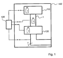
- Fig. 1 schematically and greatly simplified shows a container treatment plant 100 for treating containers 2, such as plastic bottles, glass bottles, metal cans, etc.
- the container treatment plant 100 consists in the embodiment shown here of a first container treatment device 110 and a second container treatment device 120. Between the first container treatment device 110 and The second container treatment device 120 is a storage device 1 according to the invention arranged. Likewise, the second container treatment device 120 is followed by a further storage device 1. It is obvious to a person skilled in the art that the container treatment system 100 can also include a plurality of the container treatment devices 110, 120 illustrated here and also more storage devices 1.
- the first container treatment device 110 may be, for example, a labeling device for labeling containers 2 with a label.
- the second container treatment device 120 is, for example, a filler for filling the containers 2 with a liquid (not shown here).
- the container treatment devices 110, 120 may also be a stretch blow molding machine for producing finished plastic containers 2, such as preform beverage bottles, a cleaning device for cleaning the containers 2, a packaging device for packaging the containers 2, etc.
- the storage devices 1 are used for storing and also for transporting the containers 2 from the individual container treatment devices 110 to downstream container treatment devices 120 or to further processing devices (not illustrated here).
- a control and regulation unit 105 is connected to the elements of the container treatment plant 100. Based on the signals that the Control unit 105 measures, the memory devices 1 are controlled accordingly to change the capacity of the individual memory devices 1 in response to the measurement signals of the control unit 105.
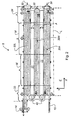
- Fig. 2 shows a plan view of a schematic representation of the memory device 1 according to the invention, which is constructed from three memory modules 30.
- the memory modules 30 of the memory device 1 are arranged parallel to one another and are located in a plane E, which in Fig. 2 is represented by the plane spanned in the X coordinate direction and the Y coordinate direction.
- the memory device 1 according to the invention consists of a front module 33 and an end module 34. At least one further intermediate module M is inserted between the front module 33 and the end module 34. In the smallest stage of expansion, the memory device 1 according to the invention consists of a front module 33, an intermediate module M and an end module 34.
- the intermediate module M arranged between the front module 33 and the end module 34 is provided with a drive device if only a single intermediate module M is provided ,
- the containers (not shown here) pass through an inlet 10 into the storage device 1.
- the containers leave the storage device 1 via an outlet 14.
- the individual storage modules 30 are spaced apart from one another by a distance A.
- the forehead module 33 further carries a transfer device 40 with which it is possible to transfer the containers 2 stored in the storage device 1 from an initial storage module 30A to a subsequent storage module 30N. Between the individual memory modules, a cover 21 is provided in this case, so that a closed surface or plane is produced. It goes without saying for a person skilled in the art that in Fig. 2 illustrated embodiment may consist of more than three and less than three memory modules 30.
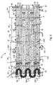
- Fig. 3 shows a plan view of the memory device 1 according to the invention, which in the first embodiment shown here also from three parallel arranged to each other memory modules 30 is constructed.
- the memory modules 30 are also spaced apart by a distance A.
- the memory device 1 according to the invention thus consists of an initial memory module 30A, a subsequent memory module 30N and a last memory module 30L.
- Each memory module 30 is associated with a transfer unit 36.
- the transfer unit 36 By means of the transfer unit 36, the containers 2 can be transferred from an infeed conveyor 31 E of a storage module 30 via the two transfer belts 31 and 32 to an outfeed conveyor 32 A of the same storage module 30.
- Each transfer unit 36 consists of an outer guide 37 and an inner guide 38.
- the outer guide 37 and the inner guide 38 serve to safely transfer the containers 2 from the infeed conveyor 31 E to the discharge conveyor 32A of the storage module 30.
- the infeed belt 31 E and the at least one transfer belt 31 of each storage module 30 are driven in the first transport direction TR1.
- the discharge belt 32A and the at least one transfer belt 32 of each storage module are driven in the second transporting direction TR2.
- a cover 21 (see, for example. Fig. 9 ) to ensure a uniform plane E of the storage device 1.
- 30 three bands 22 are used in the distance A between two successive memory modules.
- the belts 22 can be driven in the direction of the first transport direction TR1.
- the container 2 thus transported can easily be removed by an operator and, if necessary, be returned to the processing or treatment process of the container 2.
- infeed belts 31 E, discharge belts 32A, transfer units 35 and belts 22 are a plurality of drive devices 51, 52, 53, 54, 55, 56 and 57 are provided.
- a first drive means 51 serves to drive the infeed conveyor 31 E of the initial storage module 30A.
- a second drive means 52 serves to drive the first transfer belt 31 following the infeed belt 31 E of the initial storage module 30A.
- a third drive means 53 serves to drive the second transfer belt 32 of the initial storage module 30A.
- a fourth drive device 54 serves to drive the endless chain 7 common to the initial memory module 30A and the subsequent memory module 30N, consisting of the outlet belt 32A of the initial memory module 30A and the infeed belt 32E of the subsequent memory module 30N and the first transfer belt 31 of the subsequent memory module 30N. Furthermore, in this embodiment, the fourth drive device can be used to drive the belts 22 provided between the storage modules, instead of a cover, for discharging overturned containers 2 in the direction TR1 of the first transport direction.
- a fifth drive device 55 serves to drive the displacement unit 35.
- a sixth drive device 56 serves to drive the endless chain 7 common to the following memory module 30N and the last memory module 30L, consisting of the outlet conveyor 32A of the subsequent storage module 30N and the infeed conveyor 31E of the last Memory module 30L, as well as the first transfer tape 31 of the last memory module 30L.
- a seventh drive device 57 serves to drive the second transfer belt 32 of the subsequent memory module 30N.
- An eighth drive device serves to drive the second transfer belt 32 of the last memory module 30L.
- the discharge belt 32A of the last storage module 30L is driven by a separate drive (not shown).
- the discharge belt 32A and the second transfer belt 32 of the last storage module 30L can be driven by a common drive (not shown).
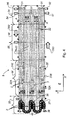
- Fig. 4 shows a second, not belonging to the invention embodiment of the memory device 1.
- the memory device 1 comprises a front module 33 and an end module 34. Between the front module 33 and the end module 34, in the case of the Fig. 4 shown representation two intermediate modules M used.
- the intermediate modules M have a uniform module length ML (see Fig. 26 ).
- Each memory module 30 is associated with a transfer unit 36. With the transfer unit 36, it is possible to transfer the containers from an infeed conveyor 31 E of a storage module 30 to an outfeed conveyor 32 A of the storage module 30.
- the transfer unit 36 can be moved with a displacement unit 35 parallel to the memory modules 30, so as to change the storage capacity of the storage device 1 according to the invention as needed.
- the memory device 1 is also constructed of three memory modules 30, wherein an initial memory module 30A, a subsequent memory module 30N and a last memory module 30L is provided.
- the containers 2 entering the storage device 1 are transferred by means of the respective transfer device 40 from the initial storage module 30A to the subsequent storage module 30N and from there to the last storage module 30L.
- the containers 2 leave the last storage module 30L via a discharge conveyor 32A associated with the last storage module 30L.
- the transfer unit 36 is provided with an inner guide 38 and an outer guide 37 so as to safely transfer the containers 2 from the infeed conveyor 31 E of a module 30 to the outfeed conveyor 32A of the same module.
- the individual memory modules 30 of the memory device 1 are spaced apart by a distance A. In the distance A, several bands 22 are also used.
- the container 2 possibly falling over in a module can be transported by means of the tapes 22 to the end module 34. Also in this embodiment ( Fig.
- a first drive means 51 serves to drive the infeed conveyor 31 E of the initial storage module 30A.
- a second drive means 52 serves to drive the first transfer belt 31 following the infeed belt 31E of the initial storage module 30A.
- a third drive means 54 drives the endless chain 7 common to the initial storage module 30A and the subsequent storage module 30N, consisting of the discharge belt 32A of the initial one Memory module 30A and the infeed conveyor 31 E of the subsequent memory module 30N, and the first transfer belt 31 of the subsequent memory module 30N.
- the third drive device 54 serves to drive the discharge belts or belts 22 provided between the storage modules 30A, 30N and 30L instead of a cover 21.
- a fourth drive device 56 serves to drive the endless chain common to the subsequent storage module 30N and the last storage module 30L 7, consisting of the outlet conveyor 32A of the subsequent storage module 30N and the infeed conveyor 31E of the last storage module 30L, and of the transfer conveyor 31 of the last storage module 30L.
- a fifth drive device 55 serves to drive the displacement unit 35.
- Fig. 5 shows a third embodiment of the memory device according to the invention 1.
- the memory device 1 according to the invention is also constructed of three individual memory modules 30, which are arranged parallel to each other with a distance A. In the distance A between the individual memory modules 30 also several bands 22 are provided, which are used analogously to the embodiments already described for the discharge of possibly fallen container 2.
- Each memory module 30 is also associated with a transfer unit 36, the container 2 from the infeed conveyor 31 E transferred to the outlet conveyor 32A of each module 30.
- the three transfer units 36 it is thus possible to transfer the containers 2 from the infeed conveyor 31 E of an initial storage module 30 A to an outfeed conveyor 32 A of the same storage module 30 A.
- a transfer device 40 is also provided in the front module 33 so that, in cooperation with the corresponding transfer unit 36, the containers 2 from the infeed conveyor 31 E via the outfeed conveyor 32A of an initial storage module 30A to an infeed conveyor 31E of a subsequent storage module 30N and further can be transferred via the outlet belt 32A on an infeed conveyor 31 E of a last memory module 30L.
- the infeed conveyor 31 E of each storage module 30 can be driven in a first transport direction TR1. Analogous to the first transport direction TR1 and the belts 22 are driven, which are arranged between the individual modules 30.
- each memory module 30 is assigned a displacement unit 35. At the displacement units 35 are on both sides a blind strip 5 (see Fig.
- the transfer units 36 are seated on the displacement unit 35.
- the displacement units 35 are arranged centrally in each of the individual memory modules 30 of the memory device 1 according to the invention.
- the discharge belt 32A of the last storage module 30L can be driven in a second transport direction TR2 so that the containers 2 can be transported out of the storage device 1 according to the invention.
- a plurality of drive means 51, 52, 53, 54, 55, 56 and 57 are provided for driving the plurality of existing in the storage device 1 intake belts 31 E, discharge belts 32 A, displacement units 35, endless chain 7, endless transfer chain 9 and belts 22 a plurality of drive means 51, 52, 53, 54, 55, 56 and 57.
- a first drive means 51 serves to drive the infeed conveyor 31 E of the initial storage module 30A.
- a second drive device 52 serves to drive the following on the infeed belt 31 E of the initial memory module 30 A endless transfer chain 9 in the first transport direction TR1.
- a third drive device 54 serves to drive the endless chain 7 which is common to the initial memory module 30A and the subsequent memory module 30N, comprising the outlet belt 32A of the initial memory module 30A and the infeed belt 31E of the subsequent memory module 30N.
- a fourth drive device 56 serves to drive the endless chain 7 common to the following storage module 30N and the last storage module 30L, consisting of the discharge belt 32A of the subsequent storage module 30N and the infeed conveyor 31E of the last storage module 30L.
- a fifth drive device 55 serves to drive the displacement unit 35.
- a sixth drive device 53 serves to drive on the endless transfer chain 9 preceding the discharge belt 32A of the subsequent storage module 30N in a second transport direction TR2.
- a seventh drive device 57 serves to drive on the endless transfer chain 9 preceding the discharge belt 32A of the last storage module 30L in a second transport direction TR2.
- the third drive means 54 may also serve to drive at least one belt 22 provided between the initial memory module 30A and the subsequent memory module 30N and between the subsequent memory module 30N and the last memory module 30L.
- Fig. 5A shows a variant of the third embodiment of the storage device 1 according to the invention with a further preferred arrangement of the drive means.
- the second drive device 52 in the front module 33.
- the third drive means 54 serves to drive the initial memory module 30A and the following memory module 30N common endless chain 7, consisting of the outlet belt 32A of the initial memory module 30A and the infeed conveyor 31 E of the subsequent memory module 30N.
- the fourth drive device 56 serves to drive the endless chain 7 common to the subsequent memory module 30N and the last memory module 30L, comprising the outlet belt 32A of the subsequent memory module 30N and the infeed conveyor 31E of the last memory module 30L.
- the third drive means 54 may also serve to drive at least one belt 22 provided between the initial storage module 30A and the subsequent storage module 30N, and the fourth drive means 56 may also serve to drive at least one belt 22 between the subsequent storage module 30N and the last memory module 30L is provided.
- the load of the bands 22 is distributed here on two drives. Due to the preferred arrangement of the drives of the third embodiment, the end module 34 can get by in the end without heels and thus increases the accessibility and increased engagement protection is given.
- the width of the infeed conveyor 31 E of the initial storage module 30 A and the width of the outfeed conveyor 32 A of the last storage module 30 L can be increased if necessary.
- the infeed belt 31 E and the outfeed belt 32A are formed by two standard chains.
- the transfer chains 7 and the endless transfer chains 9 are already made wider due to traction.
- Fig. 6 schematically shows the embodiment of a memory module 30, as in the in Fig. 3 described embodiment of the storage device 1 according to the invention is used.
- the memory module 30 has a Infeed belt 31 E and a transfer belt 31, which are driven in a first transport direction TR1.
- a discharge belt 32A and a transfer belt 32 are drivable in a second transport direction TR2. Consequently, two transfer belts 31 and 32 are thus provided between the infeed belt 31 E and the outfeed belt 32A.
- the memory module 30 is also associated with a displacement unit 35.
- the memory module 30 is also associated with a transfer unit 36.
- the transfer unit 36 comprises an outer guide 37 and an inner guide 38.
- the containers 2 enter the module 30 via the infeed conveyor 31 E.
- the transfer unit 36 transfers the containers 2 from the infeed conveyor 31 E of the module 30 to the outfeed conveyor 32 A of the same module 30.
- the outer guide 37 and the inner guide 38 of the transfer unit 36 form an alley 363 (see Fig. 33 and 34 ), so that the container 2 can be transferred from the infeed conveyor 31 E via the two transfer belts 31 and 32 to the outlet conveyor 32A.
- Fig. 7 shows a plan view of another embodiment of the memory module 30, as in the in Fig. 4 described embodiment of the storage device 1 is used.
- the memory module 30 has an infeed belt 31 E and a transfer belt 31, which can be driven in a first transport direction TR1.
- a discharge belt 32A is drivable in a second transport direction TR2.
- the second transfer belt 32 is at the same time the outfeed belt 32A of the embodiment of the storage module 30 shown here.
- at least one further first transfer belt 31 is arranged between the infeed belt 31E and the outfeed belt 32A.
- the memory module 30 may also be associated with a displacement unit 35, with which the transition unit 36 of each memory module 30 can be moved depending on the required storage capacity.
- the transfer unit 36 for the memory module 30 of in Fig. 7 also has an outer guide 37 and an inner guide 38.
- the outer guide 37 and the inner guide 38 form together an alley 363 (see Fig. 33 and 34
- the outer guide 37 and the inner guide 38 are formed in the region of the infeed belt 31 E and the adjacent first transfer belt 31 of the storage module 30 such that the formed lane 363 extends substantially obliquely over the at least one first transfer belt 31 , The containers 2 thus arrive directly on the outlet conveyor 32A of the storage module 30.
- Fig. 8 shows an embodiment of the memory module 30, as in the embodiment of the memory device 1 from Fig. 5 Use finds.
- the memory module 30 comprises an infeed belt 31 E, which is driven in a first transport direction TR1. Furthermore, the memory module 30 comprises a second outlet belt 32A, which can be driven in a second transport direction TR2. Furthermore, a further first transfer belt 31 and a further second transfer belt 32 are provided between the infeed belt 31 E and the outfeed belt 32A of each storage module 30.
- the first transfer belt 31 and second transfer belt 32 provided between the infeed belt 31 E and the outfeed belt 32A are formed as an endless transfer chain 9.
- the shifting unit 35 for the transfer unit 36 assigned to each storage module 30 is arranged centrally in each storage module 30 in this embodiment.
- the transfer unit 36 is seated on the displacement unit 35, which in turn is connected to a blind strip 5 on both sides.
- the blind strip 5 thus forms a uniform closed surface or plane E for each memory module 30.
- the respective transfer unit 36 transfers the containers 2 from the infeed conveyor 31 E to the outfeed conveyor 32A of the storage module 30.
- Each transfer unit 36 has the in Fig. 8 described embodiment, the endless transfer chain 9, which consists of the individual transfer belts 31 and 32.
- the course of the endless transfer chain 9 follows the first transfer belt 31 to the first deflection pulley 11 with a first transport direction TR1, is deflected horizontally on the deflection plate 11 and thus passes as a transfer belt 32 in the second transport direction TR2.
- the second Transfer belt now deflected vertically and follows a guide below the closed surface or level E in a first transport direction TR1 to the renewed vertical deflection at the end module 34.
- the second transfer chain 32 is again above the closed surface or plane E and extends again in the second transport direction TR2 to the second horizontal deflection 12.
- the second transfer belt 32 is deflected again and thus again to the first transfer belt 31 in a first transport direction TR1.
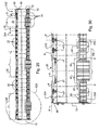
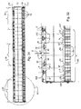
- Fig. 9 shows a plan view of the first embodiment of the storage device 1 according to the invention, in which the storage capacity of the storage device 1 is fully utilized.
- the memory device 1 consists of the front module 33 and the end module 34. Between the front module 33 and the end module 34 are in the in Fig. 9 illustrated embodiment, three intermediate modules M used.
- the memory device 1 has three memory modules 30 which are arranged parallel to each other and at a distance A. At the in Fig. 9 In the embodiment shown, no strips 22 are inserted in the distance A between the memory modules 30. Instead of the bands 22, it is also possible to use a cover 21, so that a uniform and closed plane E can be achieved for the storage device 1.
- the containers 2 enter the storage device 1 along a feed belt 31 E of an initial storage module 30 A along a first transport direction TR 1. Finally, the containers 2 leave the storage device 1 via a discharge belt 32A of a last storage module 30L of the storage device 1 along a second transport direction TR2.
- the transfer units 36 one of which is assigned to a storage module 30, are located in the area of the end module 34 of the storage device 1 Fig. 9 shown position of the transfer units 36, the full storage capacity of the storage device 1 can be availed.
- a transfer device 40 is arranged between each two consecutive modules 30.
- the transfer device 40 located between the initial storage module 30A and the subsequent storage module 30N it is possible to transfer the containers 2 from the discharge belt 32A of the initial storage module 30A to the infeed conveyor 31E of the subsequent storage module 30N.
- the transfer device 40 arranged between the subsequent storage module 30N and the last storage module 30L it is possible to transfer the containers 2 from the discharge belt 32A of the subsequent storage module 30N to the infeed conveyor 31E of the last storage module 30L.
- a transfer device 40 is provided between two successive memory modules 30.
- Each transfer device 40 essentially consists of an endless chain 7 and an upper deflector 44 and lower deflector 45 attached to the front module 33 (see FIG Fig. 11 ).
- the upper deflector 44 and the lower deflector 45 are arranged in the storage device 1 such that the endless chain 7 forms the discharge belt 32A of the initial storage module 30A and the entry belt 31E of the subsequent storage module 30N.
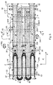
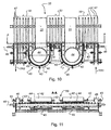
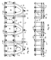
- Fig. 10 shows a plan view of a first embodiment of the front module 33 of the memory device according to the invention 1.
- the front module 33 is designed for a memory device 1, which is constructed from three memory modules 30.
- the memory module 30 carries a plurality of support rails 47 on which the driven conveyor belts run.
- a transfer device 40 is arranged between two successive memory modules 30 .
- the transfer device 40 consists of an upper deflection 44 and a lower deflection 45 (see Fig. 11 ). By means of the upper deflection 44 and the lower deflection 45, the endless chain 7 is deflected, which thus, as already in Fig.
- both the outlet belt 32A of the initial module 30A and the infeed conveyor 31 E of the subsequent memory module 30N forms.
- the containers 2 (not shown here) enter the front module 33 in the first transport direction TR1.
- the containers 2 leave the front module 33 along the second transport direction TR2.
- a cover 21 is provided between the parallel memory modules 30 .
- the cover 21 is required for the storage device 1 to form the uniform and closed plane E.
- the endless chain 7 is placed around the circular upper deflection 44.
- the outer edge of the endless chain 7 is assigned a railing 42. By means of the railing 42 prevents container 2 fall during the deflection of the endless chain 7 of the storage device 1.
- the railing 42 can be adapted to the container 2 to be stored with the storage device 1, so that a free and unhindered transport or deflection of the container 2 within the storage device 1 is ensured.
- all drive shafts 48 are connected to the front module 33, via which the individual conveyor belts can be driven by means of motors (not shown here).
- Fig. 11 shows a view of the end module 33, from the in Fig. 10 Viewing direction AA.
- the rail 42 and the rail railings 46 associated with the upper deflector 44 may each be adjusted to the width of the containers 2 to be transported by a plurality of adjustment members 43.
- Fig. 11 also shows the upper deflection 44 associated lower deflection 45 for the endless chain. 7
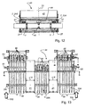
- Fig. 12 shows a detail view of in Fig. 10
- the cross-section 42 is arranged in such a way that it is spaced from the surface of the upper deflection 44 and the endless chain 7 looped around the upper deflection 44.
- the upper deflector 44 and the lower deflector 45 are about a common axis 25 rotatably formed. Due to the rotatability of the upper deflection 44 and the lower deflection 45, the deflection of the endless chains 7 is facilitated.
- the endless chain 7 rests with an edge on the upper deflection 44 or on the lower deflection 45. With the other edge, the endless chain 7 abuts a guide 27. Thus, the endless chain 7 is completely guided and can not jump out.
- Fig. 13 shows a plan view of a first embodiment of the end module 34 of the memory device 1.
- the in Fig. 13 illustrated embodiment of the end module 34 is suitable for a memory device 1, which is composed of three memory modules 30.
- a cover 21 is provided, so that the uniform and closed plane E of the storage device 1 is achieved.
- the end module 34 essentially serves to deflect the conveyor belts of the individual memory modules 30, so that they are guided in the lower region of the memory device 1 back to the front module 33.
- the initial memory module 30A, the subsequent memory module 30N and the last memory module 30L are traversed by a plurality of waves 60 to 63. From the shaft 60 can attack a corresponding drive means.
- the shaft 60 carries a plurality of discs 64, so that a plurality of conveyor belts can be driven or deflected.
- the initial memory module 30A is further associated with a shaft 62 which may also be connected to a drive means. On the shaft 62 also sit several discs 65, by means of which the conveyor belts of the initial memory module 30 A can be driven or deflected.
- a shaft 61 which extends into the area of the subsequent memory module 30N is enough.
- a plurality of disks 64 by means of which the conveyor belts of the subsequent storage module 30N can be driven or deflected, likewise sit in this region of the subsequent storage module 30N.
- a shaft 63 which also carries a plurality of discs 66. By means of these discs 66 it is possible to drive or deflect the conveyor belts of the last memory module 30L.
- Fig. 14 shows a view of the end module 34 from Fig. 13 along the in Fig. 13 with AA marked cutting line.
- each storage module 30 is assigned a plurality of support rails 47.
- the individual memory modules 30 are spaced apart from one another by means of the cover 21.
- the shaft 61 By means of the shaft 61, essentially the conveyor belts (not shown here) of the following memory module 30N can be driven.
- the conveyor belts are returned to the end module 33.
- Fig. 15 shows a sectional view of the in Fig. 13 with BB marked cutting line.
- the shaft 62 is seated as out Fig. 13
- the disks 65 seated on the shaft 62 serve to guide, divert and / or drive the individual conveyor belts (not shown) of the initial storage module 30A.
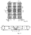
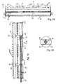
- Fig. 16 shows a plan view of an embodiment of a memory module M, which is inserted between the front module 33 and the end module 34.
- This in Fig. 16 Also shown on this shaft 67 is a drive device, which ultimately ensures the movement of the displacement units 35 both in the first transport direction TR1 and in the second transport direction TR2.
- This in Fig. 16 shown intermediate module M must be arranged at least between the end module 34 and the front module 33, because only so it is possible, the displacement units 35 according to the required storage capacity of the Storage device 1 to proceed.
- the intermediate module M also consists of three individual memory modules 30, which are arranged at a distance A from one another.
- the cover 21 is arranged so as to create a uniform and closed surface or plane E of the memory device or of the intermediate module M.
- the individual memory modules 30 carry the support rails 47 for the conveyor belts (not shown) of the storage device 1.
- Fig. 17 shows a sectional view of the in Fig. 16 AA section line and thus the side view of a frame member 73, as used in the construction of the intermediate module M.
- the frame member 73 carries a tab 74.
- the tab 74 has a plurality of holes 76 formed.
- a plurality of bores 75 are formed at the end of the frame part 73, which is opposite to the tab 74.
- the intermediate module M can be connected to a further intermediate module M via the tab 74.
- Fig. 18 shows a section through the intermediate module M along in Fig. 16 illustrated section line CC.
- the intermediate module M is constructed box-shaped.
- the plurality of support rails 47 are mounted on which the conveyor belts (not shown) of the individual memory modules 30 are guided.
- the memory modules 30 are also spaced apart by a distance A.
- at least one guide shaft 78 is arranged within the box-shaped construction of the intermediate module M.
- the guide shaft 78 it is possible to return the conveyor belts in the inner region I of the intermediate module M from the end module 34 to the front module 33.
- the first transfer belts 31, the second transfer belts 32, the infeed belts 31 E, the discharge belts 32 A, the shifting unit 35 and the belts 22 rest on correspondingly assigned rollers 79 of the guide shaft 78.
- Fig. 19 shows a view of the intermediate module M along the in Fig. 16 with BB marked cutting line.
- the shaft 67 of the intermediate module M are associated with two further guide shafts 78, which also (not shown) to carry a plurality of rollers 79 for guiding the conveyor belts.
- the guide shaft 78 carries a plurality of guide rollers 80, wherein each guide roller 80 is assigned directly to the displacement unit 35 on the upper side 70 of the intermediate module M.
- the shaft 67 is in direct operative contact with the displacement unit 35 by the drive wheels 68.
- the drive device (not shown) connected to the shaft 67 is actuated if an increased capacity is required within the memory device 1 for storing the containers 2.
- the displacement unit 35 can be moved according to the required storage capacity on the upper side 70 of the intermediate module M.
- the intermediate module M is provided on the bottom 71 with a cover 81.
- Fig. 20 shows an enlarged view of the in Fig. 19 marked with K19 area.
- the cover 81 is also modular.
- the individual modules of the cover 81 can be connected to each other with a screw 82 and a nut 83. In this way, a quick and easy access to the interior I of the memory module M is also possible.
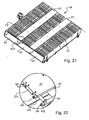
- Fig. 21 shows a perspective view of the intermediate module M, which is connected to a drive device for moving the displacement unit 35 (not shown here) along the intermediate module M.
- the box construction of the intermediate module M becomes apparent.
- the intermediate module M is provided with the cover 81.
- the frame parts 73 are provided, which connect the upper side 70 to the underside 71 of the intermediate module M.
- Fig. 22 shows an enlarged view of the in Fig. 21 marked with K21 area.
- the cover 21 has formed at least one tab 21 L.
- the support rails 47 each have a tab 47L formed.
- the tabs 21 L and 47 L it is possible to connect intermediate modules M with each other.
- the tabs 21 L of the cover 21 and the tabs 47 L of the support rails 47 corresponding fasteners 84, with which the individual and successive intermediate modules M of the storage device 1 can be interconnected.
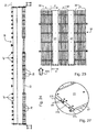
- Fig. 23 shows a plan view of an intermediate module M, which is provided only for the guidance of the conveyor belts of the storage device 1.
- This in Fig. 23 shown intermediate module M serves only to increase the length or the storage capacity of the storage device 1.
- the intermediate module M is analogous to that already in Fig. 16 described intermediate module M also from three memory modules 30, which at a distance A are arranged to each other. At the distance A between the memory modules 30, the cover 21 is provided.
- Fig. 24 shows a view of the intermediate module M from the first transport direction TR1.
- the guide shaft 78 carries a plurality of rollers 79, which are provided for the return of the moving on the upper side 70 of the intermediate module M conveyor belts (not shown here).
- the conveyor belts are located on the upper side 70 of the intermediate module M on the support rails 47 provided therefor.
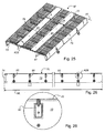
- Fig. 25 shows a perspective view of the intermediate module M, which includes no drive means for the movement of the displacement unit 35.
- the intermediate module M is also shown in a box-shaped design and carries at least two lateral frame parts 73 for stabilization or for holding other components (not shown).
- Fig. 26 shows a view along the in Fig. 23 illustrated section line AA.
- the frame part 73 likewise comprises a tab 74, by means of which the individual and successive intermediate modules M of the storage device 1 can be connected.
- the frame part 73 carries a plurality of receptacles 85 which serve to secure further components (not shown) of the storage device 1.
- Fig. 27 shows an enlarged view of the in Fig. 25 marked with K25 area.
- the cover 21 is provided with at least one tab 21 L.
- each support rail 47 is provided with a tab 47L.
- the tabs 21 L and 47 L carry corresponding fastening elements 84, with which it is possible to connect the individual and successive intermediate modules M with each other.
- Fig. 28 shows an enlarged view of the Fig. 26 marked with K26 area.
- the frame part 73 carries a plurality of receptacles 85, which serve for the attachment of a further component (not shown) of the storage device 1.
- Fig. 29 shows a sectional view of the in Fig. 5 illustrated third embodiment of the memory device 1 along the section line SS.
- three memory modules 30 are also arranged parallel to each other.
- conveyor belts 22 are provided, which can be driven along the first transport direction TR1, so that possibly fallen containers 2 can be transported in the direction of the end module 34.
- a guide shaft 78 is mounted, which forms a guide for the conveyor belts with the rollers 79 in order to convey them back to the end module 33 of the storage device 1.
- the individual conveyor belts such as, for example, the infeed belts 31 E, the first transfer belts 31, the second transfer belts 32, the discharge belts 32 A, the belts 22 and the displacement units 35 rest on a plurality of rollers 79.
- the first transport direction TR1 is directed into the plane of the drawing.
- the displacement unit 35 is arranged, of which the shutter strip 5 (see Fig. 30 ) is shown.
- Fig. 30 shows an enlarged view of the in Fig. 29 marked with K29 area.
- the configuration of the last memory module 30L will be described.
- On the upper side 70 of the memory device 1 are the individual conveyor belts of the last memory module 30L on the guides 47 provided for this purpose.
- the discharge belt 32A of the last storage module 30L has on the side facing the guides 47 two extensions 90, which provide lateral stabilization and guidance of the outgoing conveyor belt 32A.
- the shutter strip 5 of the displacement unit 35 is provided in the middle between the incoming conveyor belt 31 E and the outgoing conveyor belt 32 A.
- the blind strip 5 has also formed two extensions 90, which provide a lateral guidance of the blind strip 5.
- the endless transfer chain 9 is arranged.
- the endless transfer chain 9 has at the guides 47 side facing a TAB guide 92.
- the endless transfer chain 9 is supported laterally on the guide 47 with the blind strip 5 from.
- the TAB guide 92 engages under the guide 47 and thus ensures safe guidance of the transfer chain 9 in the plane E.
- the infeed belt 31 E of the last memory module 30 L is also formed with a TAB guide 92.
- a lateral guide is obtained between the support rails 47 and at the same time a guide of the infeed conveyor 31 E within the plane E.
- Fig. 31 is also the sectional view of in Fig. 5 illustrated embodiment of the storage device 1 along the section line SS shown.
- the difference of Fig. 31 to Fig. 29 is that the individual conveyor belts or the requirements of the individual conveyor belts are designed differently.
- the guide shaft 78 arranged between the lateral frame parts 73 carries a multiplicity of rollers 79, all of which have the same diameter.
- the rollers 79 for guiding the blind strip 5 below the top 70 of the storage device 1 formed with the same diameter as the other rollers 79th
- Fig. 32 shows an enlarged view of the in Fig. 31 marked with K31 area.
- the last memory module 30L will also be described in cross-section.
- the design of the individual conveyor belts in the other memory modules 30 is analog.
- the outgoing conveyor belt 32A in the last memory module 30L has two extensions 90 with which the outgoing conveyor belt 32A is laterally supported on the support rails 47.
- the shutter strip 5 of the displacement unit 35 is provided in the middle between the infeed conveyor 31 E and the outlet conveyor 32A.
- the blind strip 5 has on the support rails 47 side facing also two extensions 90 with which the blind strip 5 is laterally supported on the support rails 47 and guided.
- the endless transfer chain 9 is provided between the incoming conveyor belt 31 E and the blind strip 5 and between the blind strip 5 and the outgoing conveyor belt 32 A.
- the endless transfer chain 9 also has on the support rails 47 side facing a TAB guide 92.
- This TAB guide 92 is guided on the support rail 47, both the outgoing conveyor belt 32A, and the endless transfer chain 9 and the incoming conveyor belt 31 E is common with the endless transfer chain 9.
- the blind strip 5 has a larger chain height D.
- higher chain can also be a thin chain with U-shaped contour or laterally mounted webs are used for the lateral increase.
- the endless transfer chain 9 is guided laterally relative to the blind strip 5 over the entire length of the memory modules, regardless of the position of the transfer unit 36.
- the deflection 11 and 12 takes over the inner guide of the transfer chain 9 with an engagement in the upper Groove 50.
- An analogous engagement of the deflections 44 and 45, as well as the guide 27 on the outside, in the TAB-guide the endless chain. 7 Thus, in turn, all endless belts 7 and 9 are secured against lateral ascent in the horizontal deflections 11, 12, 44 and 45.
- Fig. 32A shows an enlarged sectional view through the displacement unit of in Fig. 31 marked with K31, but with another preferred variant of the TAB chains and their leadership.
- the last memory module 30L will also be described in cross-section.
- the design of the individual conveyor belts in the other memory modules 30 is analog.
- the outgoing conveyor belt 32A in the last memory module 30L has two extensions 90 with which the outgoing conveyor belt 32A is laterally supported on the support rails 47.
- the first deflecting plate 11 of the displacement unit 35 is provided in the middle between the infeed conveyor 31 E and the outlet conveyor 32 A.
- the deflection plate 11 is rotatably mounted on a displacement unit 35, and the displacement unit 35 is supported and guided by support rails 47.
- the endless transfer chain 9 is provided between the incoming conveyor belt 31 E and the deflection plate 11, and between the deflection plate 11 and the outgoing conveyor belt 32 A.
- the endless transfer chain 9 also has a TAB guide 92 on the side facing the support rails 47. This TAB guide 92 is guided laterally on the support rail 47, which both the outgoing conveyor belt 32A, and the endless transfer chain 9 and the incoming conveyor belt 31st E is common to the endless transfer chain 9.
- the deflection takes over 11 and 12, the inner guide of the transfer chain 9 with an engagement in the upper groove 50.
- the outer guide the endless transfer chain 9 in the region of the displacement unit 35 is also carried by an opposite circular guide incorporated into the support plate ( Analogously, an engagement of the deflections 44 and 45, and the guide 27 on the outside, in the TAB-guide the endless chain 7.
- an opposite circular guide incorporated into the support plate ( Analogously, an engagement of the deflections 44 and 45, and the guide 27 on the outside, in the TAB-guide the endless chain 7.
- Fig. 33 shows a perspective view of three transfer units 36, each of which is associated with a memory module 30.
- Each transfer unit 36 comprises an outer guide 37 and an inner guide 38.
- the outer guide 37 and the inner guide 38 are arranged such that a lane 363 is formed, in which the container 2 to be stored or fed from the infeed conveyor 31 E of Memory module 30 are transferred to a discharge belt 32 A of the memory module 30.
- the individual transfer units 36 are mounted on a support frame 3.
- the entire support frame 3 sits on the displacement unit 35.
- two displacement units 35 are provided so that at least two supports 360 are provided which connect the support frame 3 with the displacement units 35. With this arrangement, it is possible to move the transfer units 36 freely and linearly over the respective memory modules 30.
- Fig. 34 shows a plan view of the support frame 3 with the arranged thereon three transfer units 36 after Fig. 33 ,
- the inner guide 38 and the outer guide 37 of each transfer unit 36 is mounted with corresponding fastening elements 39 on the support frame 3.
- the outer guide 37 can be replaced by a clothing part. This is inserted into a prepared guide and locked by means of a quick release.
- To change the transfer unit is moved in the transport direction TR1 to the end module 34, since there is a free access to all memory modules 30 of the storage device 1 is given.
- z. B the width of an alley 363 are changed.
- Fig. 35 shows a front view of the arrangement of the transfer units 36 after Fig. 33 in the transport direction.
- arms 41 hangs the inner guide 38 and the outer guide 37 of each transfer unit 36th Die Rods or supports 360, which support the transfer units 36 on the displacement unit 35, are also adjustably attached to the support frame 3.
- the arms 41 carry adjusting elements 49 (see Fig. 35 ), with which it is easily possible to change the width of the lane or the position of the outer guide 37.
- Fig. 36 shows the view from the in Fig. 34 with AA marked cutting line.
- the transfer unit 36 is adjustably mounted with arms 41 on the support frame 3.
- One of the support arms 41 carries the inner guide 38, which consists of two guide elements.
- another arm 41 carries the outer guide 37, which also consists of two independently adjustable guide elements.
- the outer guide 37 is itself arranged on an adjusting element 49. With the adjusting element 49, it is possible, the width of the passage formed by the inner guide 38 and the outer guide 37 363 (see Fig. 33 ).
- the support frame 3 sits on the displacement unit 35.
- the support frame 3 can be moved by means of the displacement unit 35 with the at least one transfer unit 36 such that a storage capacity of the storage device 1 can be set.
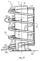
- Fig. 37 shows a further embodiment of the memory device according to the invention 1.
- a memory module 30 is formed into a vertical helix 20.
- the helix 20 is mounted on a carrier 23 and extends in the vertical direction V.
- the memory module 30 also includes a front module 33 and an end module 34. Between the front module 33 and the end module 34 at least one intermediate module M is inserted.
- the number of intermediate modules M between the front module 33 and the end module 34 depends on the total length required for the memory device 1.
- the intermediate modules M are correspondingly bent in the form of the helix 20 and have a constant module length ML.
- the running into the storage device 1 container 2 are transported along the helix 20 via an infeed conveyor 31 E in the vertical direction V.
- the memory module 30 also has a displacement unit 35, on which the transfer unit 36 sits.
- the transfer unit 36 By means of the transfer unit 36, the containers 2 are transferred from the infeed conveyor 31 E to the outfeed conveyor 32 A of the storage module 30.
- the outlet conveyor 32A in turn leads the containers 2 back to the front module 33, which in the area of the footprint 130 for the storage device 1 according to the in FIG Fig. 37 is shown embodiment.
- the displacement unit 35 is, as already described, moved along the memory module 30 shaped to form the helix 20, in order thus to change the memory capacity of the memory device 1.
- the transfer of the containers 2 from the incoming band 31 E to the outgoing band 32A has already been dealt with in detail in the previously described embodiments.
- the invention also discloses a method for storing containers 2 according to the FIFO principle.
- a storage device 1 receives from a first container handling device 110 (see FIG Fig. 1
- the infeed belt 31 E is part of a storage module 30 of the storage device 1.
- the containers 2 which are located in the storage device 1 are provided by means of a transfer unit 36 which has an inner guide 38 and an outer guide 37, from the infeed conveyor 31 E of the memory module 30 to an outfeed conveyor 32 A of the memory module 30 or the memory device 1.
- the container 2 are guided when passing from the infeed conveyor 31 E on the outlet conveyor 32 A via at least two further drivable conveyor belts 31, 32.
- a control and regulating unit 105 is provided, which is connected to the container treatment plant 100.
- the memory module 30 and the memory modules 30 are each assigned a displacement unit 35, so that with the displacement unit 35, the transfer unit 36 due to the required storage capacity can be moved parallel along the infeed conveyor 31 E and the outlet conveyor 32A.
- the required storage capacity is from determined the control unit 105 and passed accordingly to the control of the displacement unit 35.
Landscapes
- Engineering & Computer Science (AREA)
- Mechanical Engineering (AREA)
- Attitude Control For Articles On Conveyors (AREA)
- Warehouses Or Storage Devices (AREA)
Claims (15)
- Dispositif de stockage (1) pour des récipients (2) fonctionnant selon le principe « premier entré - premier sorti » (FIFO), avecau moins une bande d'entrée (31 E) qui peut être entraînée dans une direction d'entrée (TR1) ;au moins une bande de sortie (32A) qui peut être entraînée dans une direction de sortie (TR2) ;un module de stockage (30) formé de l'au moins une bande d'entrée (31 E) et de l'au moins une bande de sortie (32A) disposées parallèlement l'une à l'autre, avec une largeur (B) et un premier bord (301) sur lequel la bande d'entrée (31 E) du module de stockage (30) pour les récipients (2) est prévu, et avec un deuxième bord (302) sur lequel une bande de sortie (32A) pour les récipients (2) est prévue ;une unité de transfert (36) qui possède un guidage extérieur (37) de telle façon que les récipients (2) puissent être transférés de la bande d'entrée (31 E) à la bande de sortie (32A) du module de stockage (30) ; etune unité de déplacement (35) au moyen de laquelle une unité de transfert (36) qui peut être déplacée selon une capacité de stockage nécessaire dans le dispositif de stockage (1) le long de la bande d'entrée (31 E) ou de la bande de sortie (32A) ;caractérisé en ce queau moins une autre bande de transfert (9, 31 ; 32) est disposée entre la bande d'entrée (31 E) et la bande de sortie (32A) du module de stockage (30), qui est sensiblement parallèle à toute la longueur (L) du module de stockage (30) de telle façon que soient disposées entre la bande d'entrée (31 E) et la bande de sortie (32A) une première bande de transfert (31) immédiatement limitrophe de la bande d'entrée (31 E), parallèle à toute la longueur (L) du module de stockage (30) et pouvant être entraînée dans le sens de l'entrée et une deuxième bande de transfert (32) directement limitrophe de la bande de sortie (32A), parallèle à toute la longueur (L) du module de stockage (30) et pouvant être entraînée dans le sens de la sortie.
- Dispositif de stockage (1) selon la revendication 1, dans lequel au moins deux modules de stockage (30) sont disposés parallèlement l'un à l'autre et dans un plan (E), chaque dispositif de transfert (40) étant prévu entre les deux modules de stockage (30) parallèles l'un à l'autre, de sorte que les récipients (2) peuvent être transférés de la bande de sortie (32A) d'un module de stockage initial (30A) à la bande d'entrée (31 E) d'un module de stockage suivant (30N).
- Dispositif de stockage (1) selon l'une des revendications 1 ou 2, dans lequel les au moins deux modules de stockage (30) sont disposés parallèlement et avec un écart (A) entre un et l'autre.
- Dispositif de stockage (1) selon la revendication 3, dans lequel une couverture (21) est introduite dans l'écart (A) entre les au moins deux modules de stockage (30) parallèles.
- Dispositif de stockage (1) selon la revendication 3, dans lequel est introduite dans l'écart (A) entre les au moins deux modules de stockage (30) parallèles au moins une bande (22) qui peut être entraînée dans la direction d'entrée (TR1) afin de transporter les récipients (2) renversés hors du dispositif de stockage (1).
- Dispositif de stockage (1) selon l'une des revendications précédentes, dans lequel le dispositif de stockage (1) se compose d'un module frontal (33), d'un module d'extrémité (34) et d'au moins un module intermédiaire (M).
- Dispositif de stockage (1) selon l'une des revendications précédentes, dans lequel une longueur (L) du dispositif de stockage (1) est formée au moyen de différents modules intermédiaires (M) ayant une longueur de module (ML) constante.
- Dispositif de stockage (1) selon l'une des revendications précédentes, dans lequel trois modules de stockage (30) forment le dispositif de stockage (1).
- Dispositif de stockage (1) selon la revendication 3, dans lequel est prévu entre deux modules de stockage (30) disposés parallèlement l'un à l'autre et se faisant suite un dispositif de transfert (40) qui se compose d'une chaîne sans fin (7) avec un renvoi supérieur (44) et un renvoi inférieur (45) disposés sur le module frontal (33), qui sont disposés dans le dispositif de stockage (1) de telle manière que la chaîne sans fin (7) forme la bande de sortie (32A) du module de stockage initial (30A) et la bande d'entrée (31 E) d'un dernier module de stockage (30L).
- Dispositif de stockage (1) selon la revendication 3, dans lequel est prévu entre au moins trois modules de stockage (30) successifs disposés parallèlement les uns aux autres un dispositif de transfert (40) qui se compose d'une chaîne sans fin (7) avec un renvoi supérieur (44) et un renvoi inférieur (45) disposés sur le module frontal (33), qui sont disposés dans le dispositif de stockage (1) de telle manière que la chaîne sans fin (7) forme la bande de sortie (32A) du module de stockage initial (30A) et la bande d'entrée (31 E) d'au moins un module de stockage intermédiaire (30N) qui suit et que la bande de sortie (32A) d'au moins un module de stockage intermédiaire (30N) suivant forme la bande d'entrée (31 E) d'un dernier module de stockage (30N).
- Dispositif de stockage (1) selon l'une des revendications 3 à 10, dans lequel sont prévues à l'intérieur du plan (E) formé par les modules de stockage (30) au moins deux unités de déplacement (35) dont chacune porte montée dessus une bande à lamelles (5) et sur lesquelles repose l'au moins une unité de transfert (36).
- Dispositif de stockage (1) selon la revendication 11, dans lequel la bande à lamelles (5) est prévue entre la bande d'entrée (31 E) et la bande de sortie (32A) de chaque module de stockage (30).
- Dispositif de stockage (1) selon la revendication 12, dans lequel la bande à lamelles (5) est disposée au milieu dans les différents modules de stockage (30).
- Dispositif de stockage (1) selon la revendication 13, dans lequel la bande à lamelles (5) présente un guide latéral pour les bandes transporteuses voisines.
- Procédé pour le stockage de récipients (2) selon le principe « premier entré - premier sorti » (FIFO), caractérisé en ce qu'il comprend les étapes suivantes :• amenée des récipients (2) par un premier dispositif de traitement des récipients (110) vers une bande d'entrée (31 E) d'un dispositif de stockage (1) ;• transfert des récipients (2) au moyen d'une unité de transfert (36) qui possède un guide extérieur (37) et éventuellement un guide intérieur (38), de la bande d'entrée (31 E) vers une bande de sortie (32A) du dispositif de stockage (1), les récipients (2) étant guidés lors du transfert de la bande d'entrée (31 E) vers la bande de sortie (32A) par au moins une autre bande de transfert (9, 31, 32) pouvant être entraînée, qui s'étend pour l'essentiel sur toute la longueur (L) du module de stockage (30) parallèlement à et entre la bande d'entrée (31 E) et la bande de sortie (32A), de telle sorte que sont disposées entre la bande d'entrée (31 E) et la bande de sortie (32A) une première bande de transfert (31) directement limitrophe de la bande d'entrée (31 E), parallèle à toute la longueur (L) du module de stockage (30) et qui peut être entraînée dans le sens de l'entrée et une deuxième bande de transfert (32) directement limitrophe de la bande de sortie (32A), parallèle à toute la longueur (L) du module de stockage (30) et pouvant être entraînée dans le sens de la sortie ;• détermination d'une capacité de stockage nécessaire au moyen d'une unité de commande et de régulation (105) de l'unité de traitement des récipients (100) ; et• déplacement d'une unité de déplacement (35) avec l'unité de transfert (36) en fonction de la capacité de stockage nécessaire, le long de la bande d'entrée (31 E) et de la bande de sortie (32A) respectivement.
Applications Claiming Priority (3)
| Application Number | Priority Date | Filing Date | Title |
|---|---|---|---|
| DE102010036771 | 2010-07-30 | ||
| DE102011001532A DE102011001532A1 (de) | 2010-07-30 | 2011-03-24 | Speichervorrichtung für Behälter und Verfahren zum Speichern von Behältern |
| EP11166392.8A EP2412650B1 (fr) | 2010-07-30 | 2011-05-17 | Dispositif de stockage pour récipients et procédé de stockage de récipients |
Related Parent Applications (2)
| Application Number | Title | Priority Date | Filing Date |
|---|---|---|---|
| EP11166392.8A Division EP2412650B1 (fr) | 2010-07-30 | 2011-05-17 | Dispositif de stockage pour récipients et procédé de stockage de récipients |
| EP11166392.8 Division | 2011-05-17 |
Publications (2)
| Publication Number | Publication Date |
|---|---|
| EP2623441A1 EP2623441A1 (fr) | 2013-08-07 |
| EP2623441B1 true EP2623441B1 (fr) | 2015-01-21 |
Family
ID=44821060
Family Applications (2)
| Application Number | Title | Priority Date | Filing Date |
|---|---|---|---|
| EP11166392.8A Active EP2412650B1 (fr) | 2010-07-30 | 2011-05-17 | Dispositif de stockage pour récipients et procédé de stockage de récipients |
| EP13166352.8A Active EP2623441B1 (fr) | 2010-07-30 | 2011-05-17 | Dispositif de stockage pour récipients et procédé de stockage de récipients |
Family Applications Before (1)
| Application Number | Title | Priority Date | Filing Date |
|---|---|---|---|
| EP11166392.8A Active EP2412650B1 (fr) | 2010-07-30 | 2011-05-17 | Dispositif de stockage pour récipients et procédé de stockage de récipients |
Country Status (4)
| Country | Link |
|---|---|
| US (2) | US8770377B2 (fr) |
| EP (2) | EP2412650B1 (fr) |
| CN (1) | CN102372160B (fr) |
| DE (1) | DE102011001532A1 (fr) |
Families Citing this family (18)
| Publication number | Priority date | Publication date | Assignee | Title |
|---|---|---|---|---|
| FR2964959B1 (fr) * | 2010-09-17 | 2012-10-26 | Sidel Participations | Convoyeur a accumulation modulaire |
| CN103339047A (zh) * | 2010-12-06 | 2013-10-02 | 弗里特伍德金牛园有限公司 | 用于控制被传送物品的流动的传送器积聚器 |
| DE102011080441B4 (de) * | 2011-08-04 | 2023-01-12 | Krones Aktiengesellschaft | Speichervorrichtung für eine Abfüllanlage und Getränkeabfüllanlage mit einer solchen Speichervorrichtung |
| DE102012206295A1 (de) * | 2012-04-17 | 2013-10-17 | Krones Ag | Abfüllanlage für Behälter und Verfahren zum Betreiben der Abfüllanlage |
| US9309058B2 (en) | 2013-03-15 | 2016-04-12 | Intelligrated Headquarters, Llc | Transfer conveyor arrangement and control |
| CN103803288B (zh) * | 2014-02-24 | 2016-06-29 | 江苏新美星包装机械股份有限公司 | 吹瓶机与灌装机之间的带缓冲储瓶机构的输送通道 |
| EP3160242B1 (fr) * | 2014-06-30 | 2024-06-05 | Foodmate B.V. | Procédé et dispositif pour transférer et tamponer des objects entre transporteurs |
| NL2014130B1 (en) * | 2015-01-14 | 2017-01-04 | Foodmate Bv | Method and apparatus for transferring and buffering objects between conveyors. |
| KR20170016188A (ko) | 2015-08-03 | 2017-02-13 | 엘지전자 주식회사 | 진공단열체 및 냉장고 |
| US9896271B1 (en) | 2016-09-29 | 2018-02-20 | Barry-Wehmiller Container Systems, Inc. | Conveyor accumulator for controlling the flow of articles being conveyed |
| CA2984217C (fr) | 2016-11-02 | 2020-01-14 | NJM Packaging Inc. | Transporteur a courroie dote d'une table d'accumulation |
| CH713483A1 (de) * | 2017-02-23 | 2018-08-31 | Rotzinger Ag | Kettenpuffer. |
| CN108689136A (zh) * | 2018-06-13 | 2018-10-23 | 苏州海顺包装材料有限公司 | 传送装置及备料车间 |
| CN109512020B (zh) * | 2018-11-17 | 2021-12-03 | 昆明鼎承科技有限公司 | 容积可调的棒状物先进先出箱式存储装置 |
| CN109357574B (zh) * | 2018-11-27 | 2024-04-05 | 湖南烈岩科技有限公司 | 应用于二氧化碳移动工作站的循环运输线 |
| DE102020207676A1 (de) * | 2020-06-22 | 2021-12-23 | Krones Aktiengesellschaft | Verfahren und Vorrichtung zum Puffern von Behältern in einer Behälterbehandlungsanlage |
| DE102020134232A1 (de) * | 2020-12-18 | 2022-06-23 | Krones Aktiengesellschaft | Thermische Behandlungsvorrichtung und Verfahren zum Betreiben der thermischen Behandlungsvorrichtung |
| CN117699166B (zh) * | 2023-12-25 | 2026-04-21 | 楚天科技股份有限公司 | 一种条包输送装置及输送方法 |
Family Cites Families (18)
| Publication number | Priority date | Publication date | Assignee | Title |
|---|---|---|---|---|
| DE2248193B2 (de) * | 1972-10-02 | 1975-03-27 | Kurt G. 7332 Eislingen Hinterkopf | Vorrichtung zum Speichern von Werkstücken, insbesondere Tuben |
| US4142626A (en) * | 1977-06-08 | 1979-03-06 | Paper Converting Machine Company | Accumulator for wound paper logs |
| US6497321B2 (en) * | 2001-03-09 | 2002-12-24 | Hartness International, Inc. | Apparatus for diverting a stream of articles |
| US4413724A (en) * | 1981-05-18 | 1983-11-08 | Mapatent, N.V. | Horizontal accumulator |
| US4513858A (en) * | 1981-05-18 | 1985-04-30 | Mapatent, N.V. | Horizontal accumulator |
| DE3907615A1 (de) * | 1989-03-09 | 1990-09-13 | Focke & Co | Vorrichtung (verpackungsmaschine) zum verpacken von gegenstaenden unterschiedlicher groesse |
| FR2745804B1 (fr) * | 1996-03-08 | 1998-04-17 | Schneider Electric Sa | Dispositif de transfert et de stockage temporaire |
| US5685414A (en) | 1996-04-19 | 1997-11-11 | Nercon Engineering & Manufacturing, Inc. | Zero back-pressure conveyor system |
| US6712220B2 (en) * | 2000-03-16 | 2004-03-30 | Fps Food Processing Systems B.V. | Sorting and packaging products |
| CA2364216A1 (fr) | 2001-12-07 | 2003-06-07 | Harry T. Pappas | Transporteur a accumulation dynamique |
| ITFI20030066A1 (it) * | 2003-03-13 | 2004-09-14 | Perini Fabio Spa | Dispositivo accumulatore a catene per prodotti e mezzi |
| GB2399797B (en) * | 2003-03-25 | 2006-04-26 | Flexlink Components Ab | A variable capacity store for elongated articles |
| DE202004016069U1 (de) * | 2004-10-16 | 2005-12-01 | Krones Ag | Vorrichtung zum Puffern von Gegenständen |
| DE202006000870U1 (de) | 2006-01-20 | 2007-02-22 | Krones Ag | Vorrichtung zum Speichern von Gegenständen |
| DE602006003532D1 (de) * | 2006-04-24 | 2008-12-18 | Specialty Conveyor Bv | Förderer zum Transport und Aufstauen von einzelnen Produkten |
| FR2907107B1 (fr) * | 2006-10-17 | 2008-12-26 | Renault Sas | Dispositif de stockage |
| FR2948649B1 (fr) * | 2009-07-29 | 2011-09-09 | Sidel Participations | Table d'accumulation d'articles pour une installation de convoyage |
| FR2953502B1 (fr) * | 2009-12-03 | 2012-05-25 | Vsm Automation | Table d'accumulation |
-
2011
- 2011-03-24 DE DE102011001532A patent/DE102011001532A1/de not_active Withdrawn
- 2011-05-17 EP EP11166392.8A patent/EP2412650B1/fr active Active
- 2011-05-17 EP EP13166352.8A patent/EP2623441B1/fr active Active
- 2011-07-26 CN CN201110209949.9A patent/CN102372160B/zh active Active
- 2011-07-28 US US13/193,448 patent/US8770377B2/en active Active
-
2014
- 2014-06-05 US US14/297,304 patent/US9181029B2/en active Active
Also Published As
| Publication number | Publication date |
|---|---|
| EP2412650B1 (fr) | 2013-07-10 |
| EP2623441A1 (fr) | 2013-08-07 |
| DE102011001532A1 (de) | 2012-02-02 |
| CN102372160A (zh) | 2012-03-14 |
| US8770377B2 (en) | 2014-07-08 |
| US9181029B2 (en) | 2015-11-10 |
| US20140284175A1 (en) | 2014-09-25 |
| EP2412650A1 (fr) | 2012-02-01 |
| CN102372160B (zh) | 2015-06-17 |
| US20120024660A1 (en) | 2012-02-02 |
Similar Documents
| Publication | Publication Date | Title |
|---|---|---|
| EP2623441B1 (fr) | Dispositif de stockage pour récipients et procédé de stockage de récipients | |
| EP2637938B1 (fr) | Machine pour traiter et/ou emballer des objets et procédé pour modifier un trajet de transport de cette machine | |
| EP2794433B1 (fr) | Installation de préparation des commandes et procédé de préparation des marchandises commandées | |
| EP2826735B1 (fr) | Section ajustable de stockage tampon d'un dispositif de convoyage et procédé de stockage intermédiaire d'articles | |
| DE19522189C2 (de) | Gruppier- und Puffervorrichtung | |
| DE4100769C2 (de) | Vorrichtung zum Fördern von Produkten in einer Verpackungsmaschine | |
| EP2346757B1 (fr) | Dispositif de séparation et de positionnement de fermetures métalliques de contenant | |
| EP3652096B1 (fr) | Dispositif de stockage et de convoyeur et procédé de fonctionnement du dispositif de stockage et de convoyeur | |
| EP3315423B1 (fr) | Machine d'emballage par emboutissage | |
| DE102011053009A1 (de) | Transfereinrichtung | |
| DE102011014495A1 (de) | Vorrichtung und Verfahren zum Gruppieren von Stückgut | |
| EP3277606A1 (fr) | Dispositif tampon | |
| EP3315420B1 (fr) | Machine d'emballage par emboutissage | |
| EP2364936A2 (fr) | Dispositif et procédé de répartition d'articles à l'intérieur d'un flux d'articles | |
| DE212010000076U1 (de) | Kommissioniereinrichtung | |
| DE102015113435A1 (de) | Transportvorrichtung sowie Transportverfahren mit einer derartigen Transportvorrichtung | |
| DE202016101207U1 (de) | Transportvorrichtung zum Reihen-weisen Umsetzen von umfallgefährdeten Stückgütern und zur Lagenbildung | |
| EP2635510A1 (fr) | Dispositif de transport pour le transport de conteneurs | |
| DE102012220479A1 (de) | Verfahren zum dynamischen Speichern und/oder Puffern von Artikeln und Förderstrecke mit einem Puffer- oder Speicherareal | |
| EP2314529B1 (fr) | Unité de transport dotée de chaînes à petits rouleaux de retenue | |
| DE10348431A1 (de) | Vorrichtung zum Palettieren | |
| EP0683118B1 (fr) | Dispositif de stockage d'objets, en particulier des récipients de stockage | |
| EP1447356B1 (fr) | Convoyeur à rouleaux pour le transport et/ou le stockage d'articles | |
| EP3678963A1 (fr) | Dispositif de transport et procédé de transport mettant en oeuvre un tel dispositif de transport | |
| DE69204224T2 (de) | Vorrichtung zum Ablenken einer sich bewegenden Reihe von Gegenständen, insbesondere für Verpackungsmaschinen. |
Legal Events
| Date | Code | Title | Description |
|---|---|---|---|
| PUAI | Public reference made under article 153(3) epc to a published international application that has entered the european phase |
Free format text: ORIGINAL CODE: 0009012 |
|
| AC | Divisional application: reference to earlier application |
Ref document number: 2412650 Country of ref document: EP Kind code of ref document: P |
|
| AK | Designated contracting states |
Kind code of ref document: A1 Designated state(s): AL AT BE BG CH CY CZ DE DK EE ES FI FR GB GR HR HU IE IS IT LI LT LU LV MC MK MT NL NO PL PT RO RS SE SI SK SM TR |
|
| 17P | Request for examination filed |
Effective date: 20140127 |
|
| RBV | Designated contracting states (corrected) |
Designated state(s): AL AT BE BG CH CY CZ DE DK EE ES FI FR GB GR HR HU IE IS IT LI LT LU LV MC MK MT NL NO PL PT RO RS SE SI SK SM TR |
|
| 17Q | First examination report despatched |
Effective date: 20140312 |
|
| GRAP | Despatch of communication of intention to grant a patent |
Free format text: ORIGINAL CODE: EPIDOSNIGR1 |
|
| INTG | Intention to grant announced |
Effective date: 20140811 |
|
| GRAS | Grant fee paid |
Free format text: ORIGINAL CODE: EPIDOSNIGR3 |
|
| GRAA | (expected) grant |
Free format text: ORIGINAL CODE: 0009210 |
|
| AC | Divisional application: reference to earlier application |
Ref document number: 2412650 Country of ref document: EP Kind code of ref document: P |
|
| AK | Designated contracting states |
Kind code of ref document: B1 Designated state(s): AL AT BE BG CH CY CZ DE DK EE ES FI FR GB GR HR HU IE IS IT LI LT LU LV MC MK MT NL NO PL PT RO RS SE SI SK SM TR |
|
| REG | Reference to a national code |
Ref country code: GB Ref legal event code: FG4D Free format text: NOT ENGLISH |
|
| REG | Reference to a national code |
Ref country code: CH Ref legal event code: EP |
|
| REG | Reference to a national code |
Ref country code: IE Ref legal event code: FG4D Free format text: LANGUAGE OF EP DOCUMENT: GERMAN |
|
| REG | Reference to a national code |
Ref country code: DE Ref legal event code: R096 Ref document number: 502011005768 Country of ref document: DE Effective date: 20150312 |
|
| REG | Reference to a national code |
Ref country code: AT Ref legal event code: REF Ref document number: 709061 Country of ref document: AT Kind code of ref document: T Effective date: 20150315 |
|
| REG | Reference to a national code |
Ref country code: FR Ref legal event code: PLFP Year of fee payment: 5 |
|
| REG | Reference to a national code |
Ref country code: NL Ref legal event code: VDEP Effective date: 20150121 |
|
| REG | Reference to a national code |
Ref country code: LT Ref legal event code: MG4D |
|
| PG25 | Lapsed in a contracting state [announced via postgrant information from national office to epo] |
Ref country code: BG Free format text: LAPSE BECAUSE OF FAILURE TO SUBMIT A TRANSLATION OF THE DESCRIPTION OR TO PAY THE FEE WITHIN THE PRESCRIBED TIME-LIMIT Effective date: 20150421 Ref country code: ES Free format text: LAPSE BECAUSE OF FAILURE TO SUBMIT A TRANSLATION OF THE DESCRIPTION OR TO PAY THE FEE WITHIN THE PRESCRIBED TIME-LIMIT Effective date: 20150121 Ref country code: SE Free format text: LAPSE BECAUSE OF FAILURE TO SUBMIT A TRANSLATION OF THE DESCRIPTION OR TO PAY THE FEE WITHIN THE PRESCRIBED TIME-LIMIT Effective date: 20150121 Ref country code: LT Free format text: LAPSE BECAUSE OF FAILURE TO SUBMIT A TRANSLATION OF THE DESCRIPTION OR TO PAY THE FEE WITHIN THE PRESCRIBED TIME-LIMIT Effective date: 20150121 Ref country code: HR Free format text: LAPSE BECAUSE OF FAILURE TO SUBMIT A TRANSLATION OF THE DESCRIPTION OR TO PAY THE FEE WITHIN THE PRESCRIBED TIME-LIMIT Effective date: 20150121 Ref country code: NO Free format text: LAPSE BECAUSE OF FAILURE TO SUBMIT A TRANSLATION OF THE DESCRIPTION OR TO PAY THE FEE WITHIN THE PRESCRIBED TIME-LIMIT Effective date: 20150421 Ref country code: FI Free format text: LAPSE BECAUSE OF FAILURE TO SUBMIT A TRANSLATION OF THE DESCRIPTION OR TO PAY THE FEE WITHIN THE PRESCRIBED TIME-LIMIT Effective date: 20150121 |
|
| PG25 | Lapsed in a contracting state [announced via postgrant information from national office to epo] |
Ref country code: IS Free format text: LAPSE BECAUSE OF FAILURE TO SUBMIT A TRANSLATION OF THE DESCRIPTION OR TO PAY THE FEE WITHIN THE PRESCRIBED TIME-LIMIT Effective date: 20150521 Ref country code: RS Free format text: LAPSE BECAUSE OF FAILURE TO SUBMIT A TRANSLATION OF THE DESCRIPTION OR TO PAY THE FEE WITHIN THE PRESCRIBED TIME-LIMIT Effective date: 20150121 Ref country code: GR Free format text: LAPSE BECAUSE OF FAILURE TO SUBMIT A TRANSLATION OF THE DESCRIPTION OR TO PAY THE FEE WITHIN THE PRESCRIBED TIME-LIMIT Effective date: 20150422 Ref country code: NL Free format text: LAPSE BECAUSE OF FAILURE TO SUBMIT A TRANSLATION OF THE DESCRIPTION OR TO PAY THE FEE WITHIN THE PRESCRIBED TIME-LIMIT Effective date: 20150121 Ref country code: LV Free format text: LAPSE BECAUSE OF FAILURE TO SUBMIT A TRANSLATION OF THE DESCRIPTION OR TO PAY THE FEE WITHIN THE PRESCRIBED TIME-LIMIT Effective date: 20150121 Ref country code: PL Free format text: LAPSE BECAUSE OF FAILURE TO SUBMIT A TRANSLATION OF THE DESCRIPTION OR TO PAY THE FEE WITHIN THE PRESCRIBED TIME-LIMIT Effective date: 20150121 |
|
| REG | Reference to a national code |
Ref country code: DE Ref legal event code: R097 Ref document number: 502011005768 Country of ref document: DE |
|
| PG25 | Lapsed in a contracting state [announced via postgrant information from national office to epo] |
Ref country code: RO Free format text: LAPSE BECAUSE OF FAILURE TO SUBMIT A TRANSLATION OF THE DESCRIPTION OR TO PAY THE FEE WITHIN THE PRESCRIBED TIME-LIMIT Effective date: 20150121 Ref country code: EE Free format text: LAPSE BECAUSE OF FAILURE TO SUBMIT A TRANSLATION OF THE DESCRIPTION OR TO PAY THE FEE WITHIN THE PRESCRIBED TIME-LIMIT Effective date: 20150121 Ref country code: SK Free format text: LAPSE BECAUSE OF FAILURE TO SUBMIT A TRANSLATION OF THE DESCRIPTION OR TO PAY THE FEE WITHIN THE PRESCRIBED TIME-LIMIT Effective date: 20150121 Ref country code: DK Free format text: LAPSE BECAUSE OF FAILURE TO SUBMIT A TRANSLATION OF THE DESCRIPTION OR TO PAY THE FEE WITHIN THE PRESCRIBED TIME-LIMIT Effective date: 20150121 Ref country code: CZ Free format text: LAPSE BECAUSE OF FAILURE TO SUBMIT A TRANSLATION OF THE DESCRIPTION OR TO PAY THE FEE WITHIN THE PRESCRIBED TIME-LIMIT Effective date: 20150121 |
|
| PLBE | No opposition filed within time limit |
Free format text: ORIGINAL CODE: 0009261 |
|
| STAA | Information on the status of an ep patent application or granted ep patent |
Free format text: STATUS: NO OPPOSITION FILED WITHIN TIME LIMIT |
|
| 26N | No opposition filed |
Effective date: 20151022 |
|
| PG25 | Lapsed in a contracting state [announced via postgrant information from national office to epo] |
Ref country code: IT Free format text: LAPSE BECAUSE OF FAILURE TO SUBMIT A TRANSLATION OF THE DESCRIPTION OR TO PAY THE FEE WITHIN THE PRESCRIBED TIME-LIMIT Effective date: 20150121 |
|
| REG | Reference to a national code |
Ref country code: CH Ref legal event code: PL |
|
| GBPC | Gb: european patent ceased through non-payment of renewal fee |
Effective date: 20150517 |
|
| PG25 | Lapsed in a contracting state [announced via postgrant information from national office to epo] |
Ref country code: MC Free format text: LAPSE BECAUSE OF FAILURE TO SUBMIT A TRANSLATION OF THE DESCRIPTION OR TO PAY THE FEE WITHIN THE PRESCRIBED TIME-LIMIT Effective date: 20150121 Ref country code: CH Free format text: LAPSE BECAUSE OF NON-PAYMENT OF DUE FEES Effective date: 20150531 Ref country code: LU Free format text: LAPSE BECAUSE OF FAILURE TO SUBMIT A TRANSLATION OF THE DESCRIPTION OR TO PAY THE FEE WITHIN THE PRESCRIBED TIME-LIMIT Effective date: 20150517 Ref country code: LI Free format text: LAPSE BECAUSE OF NON-PAYMENT OF DUE FEES Effective date: 20150531 |
|
| REG | Reference to a national code |
Ref country code: IE Ref legal event code: MM4A |
|
| PG25 | Lapsed in a contracting state [announced via postgrant information from national office to epo] |
Ref country code: SI Free format text: LAPSE BECAUSE OF FAILURE TO SUBMIT A TRANSLATION OF THE DESCRIPTION OR TO PAY THE FEE WITHIN THE PRESCRIBED TIME-LIMIT Effective date: 20150121 |
|
| REG | Reference to a national code |
Ref country code: FR Ref legal event code: PLFP Year of fee payment: 6 |
|
| PG25 | Lapsed in a contracting state [announced via postgrant information from national office to epo] |
Ref country code: GB Free format text: LAPSE BECAUSE OF NON-PAYMENT OF DUE FEES Effective date: 20150517 Ref country code: IE Free format text: LAPSE BECAUSE OF NON-PAYMENT OF DUE FEES Effective date: 20150517 |
|
| PG25 | Lapsed in a contracting state [announced via postgrant information from national office to epo] |
Ref country code: MT Free format text: LAPSE BECAUSE OF FAILURE TO SUBMIT A TRANSLATION OF THE DESCRIPTION OR TO PAY THE FEE WITHIN THE PRESCRIBED TIME-LIMIT Effective date: 20150121 |
|
| REG | Reference to a national code |
Ref country code: FR Ref legal event code: PLFP Year of fee payment: 7 |
|
| PG25 | Lapsed in a contracting state [announced via postgrant information from national office to epo] |
Ref country code: HU Free format text: LAPSE BECAUSE OF FAILURE TO SUBMIT A TRANSLATION OF THE DESCRIPTION OR TO PAY THE FEE WITHIN THE PRESCRIBED TIME-LIMIT; INVALID AB INITIO Effective date: 20110517 Ref country code: SM Free format text: LAPSE BECAUSE OF FAILURE TO SUBMIT A TRANSLATION OF THE DESCRIPTION OR TO PAY THE FEE WITHIN THE PRESCRIBED TIME-LIMIT Effective date: 20150121 |
|
| PG25 | Lapsed in a contracting state [announced via postgrant information from national office to epo] |
Ref country code: CY Free format text: LAPSE BECAUSE OF FAILURE TO SUBMIT A TRANSLATION OF THE DESCRIPTION OR TO PAY THE FEE WITHIN THE PRESCRIBED TIME-LIMIT Effective date: 20150121 |
|
| REG | Reference to a national code |
Ref country code: AT Ref legal event code: MM01 Ref document number: 709061 Country of ref document: AT Kind code of ref document: T Effective date: 20160517 |
|
| PG25 | Lapsed in a contracting state [announced via postgrant information from national office to epo] |
Ref country code: BE Free format text: LAPSE BECAUSE OF NON-PAYMENT OF DUE FEES Effective date: 20150531 |
|
| PG25 | Lapsed in a contracting state [announced via postgrant information from national office to epo] |
Ref country code: TR Free format text: LAPSE BECAUSE OF FAILURE TO SUBMIT A TRANSLATION OF THE DESCRIPTION OR TO PAY THE FEE WITHIN THE PRESCRIBED TIME-LIMIT Effective date: 20150121 Ref country code: AT Free format text: LAPSE BECAUSE OF NON-PAYMENT OF DUE FEES Effective date: 20160517 |
|
| REG | Reference to a national code |
Ref country code: FR Ref legal event code: PLFP Year of fee payment: 8 |
|
| PG25 | Lapsed in a contracting state [announced via postgrant information from national office to epo] |
Ref country code: PT Free format text: LAPSE BECAUSE OF FAILURE TO SUBMIT A TRANSLATION OF THE DESCRIPTION OR TO PAY THE FEE WITHIN THE PRESCRIBED TIME-LIMIT Effective date: 20150121 Ref country code: MK Free format text: LAPSE BECAUSE OF FAILURE TO SUBMIT A TRANSLATION OF THE DESCRIPTION OR TO PAY THE FEE WITHIN THE PRESCRIBED TIME-LIMIT Effective date: 20150121 |
|
| PG25 | Lapsed in a contracting state [announced via postgrant information from national office to epo] |
Ref country code: AL Free format text: LAPSE BECAUSE OF FAILURE TO SUBMIT A TRANSLATION OF THE DESCRIPTION OR TO PAY THE FEE WITHIN THE PRESCRIBED TIME-LIMIT Effective date: 20150121 |
|
| REG | Reference to a national code |
Ref country code: FR Ref legal event code: PLFP Year of fee payment: 13 |
|
| P01 | Opt-out of the competence of the unified patent court (upc) registered |
Effective date: 20230523 |
|
| PGFP | Annual fee paid to national office [announced via postgrant information from national office to epo] |
Ref country code: DE Payment date: 20250402 Year of fee payment: 15 |
|
| PGFP | Annual fee paid to national office [announced via postgrant information from national office to epo] |
Ref country code: FR Payment date: 20250401 Year of fee payment: 15 |