EP2623711A2 - Procédé et appareil de commande de moteur de turbine à gaz à rotor ouvert avec rotors contrarotatifs - Google Patents
Procédé et appareil de commande de moteur de turbine à gaz à rotor ouvert avec rotors contrarotatifs Download PDFInfo
- Publication number
- EP2623711A2 EP2623711A2 EP13154022.1A EP13154022A EP2623711A2 EP 2623711 A2 EP2623711 A2 EP 2623711A2 EP 13154022 A EP13154022 A EP 13154022A EP 2623711 A2 EP2623711 A2 EP 2623711A2
- Authority
- EP
- European Patent Office
- Prior art keywords
- rotor
- aft
- differential
- average
- blade pitch
- Prior art date
- Legal status (The legal status is an assumption and is not a legal conclusion. Google has not performed a legal analysis and makes no representation as to the accuracy of the status listed.)
- Withdrawn
Links
- 238000000034 method Methods 0.000 title claims description 22
- 239000000446 fuel Substances 0.000 claims description 28
- 230000009466 transformation Effects 0.000 claims description 17
- 238000009530 blood pressure measurement Methods 0.000 claims description 3
- 238000013507 mapping Methods 0.000 abstract description 6
- 230000001143 conditioned effect Effects 0.000 abstract description 4
- 230000009897 systematic effect Effects 0.000 abstract description 3
- 230000001131 transforming effect Effects 0.000 abstract description 3
- URWAJWIAIPFPJE-YFMIWBNJSA-N sisomycin Chemical compound O1C[C@@](O)(C)[C@H](NC)[C@@H](O)[C@H]1O[C@@H]1[C@@H](O)[C@H](O[C@@H]2[C@@H](CC=C(CN)O2)N)[C@@H](N)C[C@H]1N URWAJWIAIPFPJE-YFMIWBNJSA-N 0.000 abstract 1
- 238000010586 diagram Methods 0.000 description 5
- 239000011159 matrix material Substances 0.000 description 5
- 230000008878 coupling Effects 0.000 description 3
- 238000010168 coupling process Methods 0.000 description 3
- 238000005859 coupling reaction Methods 0.000 description 3
- 238000013459 approach Methods 0.000 description 2
- 230000003993 interaction Effects 0.000 description 2
- 238000010348 incorporation Methods 0.000 description 1
Images


Classifications
-
- B—PERFORMING OPERATIONS; TRANSPORTING
- B64—AIRCRAFT; AVIATION; COSMONAUTICS
- B64C—AEROPLANES; HELICOPTERS
- B64C11/00—Propellers, e.g. of ducted type; Features common to propellers and rotors for rotorcraft
- B64C11/30—Blade pitch-changing mechanisms
- B64C11/306—Blade pitch-changing mechanisms specially adapted for contrarotating propellers
- B64C11/308—Blade pitch-changing mechanisms specially adapted for contrarotating propellers automatic
-
- F—MECHANICAL ENGINEERING; LIGHTING; HEATING; WEAPONS; BLASTING
- F01—MACHINES OR ENGINES IN GENERAL; ENGINE PLANTS IN GENERAL; STEAM ENGINES
- F01D—NON-POSITIVE DISPLACEMENT MACHINES OR ENGINES, e.g. STEAM TURBINES
- F01D1/00—Non-positive-displacement machines or engines, e.g. steam turbines
- F01D1/24—Non-positive-displacement machines or engines, e.g. steam turbines characterised by counter-rotating rotors subjected to same working fluid stream without intermediate stator blades or the like
-
- F—MECHANICAL ENGINEERING; LIGHTING; HEATING; WEAPONS; BLASTING
- F01—MACHINES OR ENGINES IN GENERAL; ENGINE PLANTS IN GENERAL; STEAM ENGINES
- F01D—NON-POSITIVE DISPLACEMENT MACHINES OR ENGINES, e.g. STEAM TURBINES
- F01D7/00—Rotors with blades adjustable in operation; Control thereof
-
- F—MECHANICAL ENGINEERING; LIGHTING; HEATING; WEAPONS; BLASTING
- F02—COMBUSTION ENGINES; HOT-GAS OR COMBUSTION-PRODUCT ENGINE PLANTS
- F02C—GAS-TURBINE PLANTS; AIR INTAKES FOR JET-PROPULSION PLANTS; CONTROLLING FUEL SUPPLY IN AIR-BREATHING JET-PROPULSION PLANTS
- F02C9/00—Controlling gas-turbine plants; Controlling fuel supply in air- breathing jet-propulsion plants
- F02C9/48—Control of fuel supply conjointly with another control of the plant
- F02C9/56—Control of fuel supply conjointly with another control of the plant with power transmission control
- F02C9/58—Control of fuel supply conjointly with another control of the plant with power transmission control with control of a variable-pitch propeller
-
- B—PERFORMING OPERATIONS; TRANSPORTING
- B64—AIRCRAFT; AVIATION; COSMONAUTICS
- B64D—EQUIPMENT FOR FITTING IN OR TO AIRCRAFT; FLIGHT SUITS; PARACHUTES; ARRANGEMENT OR MOUNTING OF POWER PLANTS OR PROPULSION TRANSMISSIONS IN AIRCRAFT
- B64D27/00—Arrangement or mounting of power plants in aircraft; Aircraft characterised by the type or position of power plants
- B64D2027/005—Aircraft with an unducted turbofan comprising contra-rotating rotors, e.g. contra-rotating open rotors [CROR]
-
- Y—GENERAL TAGGING OF NEW TECHNOLOGICAL DEVELOPMENTS; GENERAL TAGGING OF CROSS-SECTIONAL TECHNOLOGIES SPANNING OVER SEVERAL SECTIONS OF THE IPC; TECHNICAL SUBJECTS COVERED BY FORMER USPC CROSS-REFERENCE ART COLLECTIONS [XRACs] AND DIGESTS
- Y02—TECHNOLOGIES OR APPLICATIONS FOR MITIGATION OR ADAPTATION AGAINST CLIMATE CHANGE
- Y02T—CLIMATE CHANGE MITIGATION TECHNOLOGIES RELATED TO TRANSPORTATION
- Y02T50/00—Aeronautics or air transport
- Y02T50/60—Efficient propulsion technologies, e.g. for aircraft
Definitions
- the present disclosure pertains to counter-rotating open-rotor (CROR) gas turbine engines; and, more specifically, control system implementations for such CROR gas turbine engines utilizing a differential gearbox mechanically coupling the two counter-rotating rotors.
- CROR counter-rotating open-rotor
- the current disclosure provides control solutions addressing such problems and relationships.
- the current disclosure provides a simple, robust and systematic solution for open rotor control with a differential gearbox.
- the two counter rotating rotors of a CROR engine are conditioned by the differential gearbox, the two rotors speeds are coupled for given input torque.
- a solution provided by the current disclosure mathematically decouples these two rotors by transforming the original individual actuator input and speed output into differential & average input and output. Because the newly formed control system representation of the plant has decoupled input/output mapping, it follows that the simple SISO control can be applied.
- the current control solutions allow a simple and well-coordinated speed phase synchronizing among the four rotors on a two-engine vehicle.
- a counter-rotating open-rotor gas turbine engine includes: a forward un-ducted rotor including a plurality of forward rotor blades and including a forward rotor angle actuator for setting blade pitch angles of the plurality of forward rotor blades; an aft un-ducted rotor including a plurality of aft rotor blades and including an aft rotor angle actuator for setting blade pitch angles of the plurality of aft rotor blades; a differential gearbox mechanically coupled between the forward and aft un-ducted rotors so that rotor speeds of the respective forward and aft un-ducted rotors are coupled for a given input torque; a gas turbine engine driving the differential gearbox and including a fuel actuator for setting the fuel flow to the gas turbine engine; and an open rotor control system including, a forward rotor blade pitch angle command (BetaF) electrically connected to the forward rotor angle actuator, an aft rotor blade
- the open rotor control system may include a differential speed regulator having an input of the differential speed feedback signal (Nd) and an output of the differential blade pitch angle command (BetaD); and an average speed regulator having an input of the average speed feedback signal (Nc) and an output of the average blade pitch angle command (BetaC).
- the open rotor control system may convert the differential blade pitch angle command (BetaD) and average blade pitch angle command (BetaC) into the forward rotor angle blade pitch angle command (BetaF) and the aft rotor blade pitch angle command (BetaA).
- the differential speed regulator and the average speed regulator may be single-input-single-output (SISO) regulators
- the open rotor control system may further include a speed phase synchronizing control architecture positioned between forward and aft rotor phase output signals and input signals to one or more of the differential and average speed regulators.
- control algorithm of the open rotor control system may treat the fuel flow impact on rotor speeds as a known disturbance and rejected by the average speed regulator.
- a counter-rotating open-rotor gas turbine engine includes: a forward un-ducted rotor including a plurality of forward rotor blades and including a forward rotor angle actuator for setting blade pitch angles of the plurality of forward rotor blades; an aft un-ducted rotor including a plurality of aft rotor blades and including an aft rotor angle actuator for setting blade pitch angles of the plurality of aft rotor blades; a differential gearbox mechanically coupled between the forward and aft un-ducted rotors so that rotor speeds of the respective forward and aft un-ducted rotors are coupled for a given input torque; and an open rotor control system that includes forward and aft output signals respectively electrically coupled to the forward rotor angle actuator and the aft rotor angle actuator, and receiving forward and aft feedback input signals; where the open rotor control system may include a control algorithm that mathematically decouples
- a method for controlling a counter-rotating open-rotor gas turbine engine, where the counter-rotating open-rotor gas turbine engine includes, (a) a forward un-ducted rotor including a plurality of forward rotor blades and including a forward rotor angle actuator for setting blade pitch angles of the plurality of forward rotor blades, (b) an aft un-ducted rotor including a plurality of aft rotor blades and including an aft rotor angle actuator for setting blade pitch angles of the plurality of aft rotor blades, (c) a differential gearbox mechanically coupled between the forward and aft un-ducted rotors so that rotor speeds of the respective forward and aft un-ducted rotors are coupled for a given input torque.
- the method may include steps of (not necessarily performed in any specific order): generating forward and aft control signals respectively for the forward rotor angle actuator and the aft rotor angle actuator; and receiving forward and aft feedback input signals; where the step of generating the forward and aft control signals utilizes a control solution that mathematically decouples the forward and aft control signals into differential and average control signals and mathematically decouples the forward and aft feedback input signals into differential and average feedback input signals.
- the differential and average control signals may be generated by a single-input-single-output (SISO) regulator based at least upon the differential and average feedback input signals.
- SISO single-input-single-output
- the forward and aft output signals may include a forward blade pitch angle command and an aft blade pitch angle command;
- the forward and aft feedback input signals may include a forward rotor speed reference signal and an aft rotor speed reference signal;
- the differential feedback input signal may be a differential speed reference signal and the average speed feedback input signal may be an average speed reference signal;
- the differential output signal may be a differential blade pitch angle command and the average output signal may be an average blade pitch angle command.
- the method may further include the step of rejecting fuel flow impact on rotor speeds as a known disturbance.
- the method may further include a step of providing a speed phase synchronizing control architecture positioned between (a) at least one of the forward and aft output signals and (b) at least one of the forward and aft feedback input signals.
- the control solution may mathematically decouple the forward and aft output signals into differential and average output signals utilizing a variable transformation, and may mathematically decouple the forward and aft feedback input signals into differential and average feedback input signals utilizing a variable transformation.
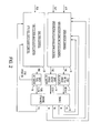
- Fig. 1 is a schematic block diagram representation of a basic control system architecture for a counter-rotating open-rotor (CROR) gas turbine engine;
- CROR counter-rotating open-rotor
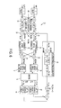
- Fig. 2 is another schematic block diagram representation of a basic control system architecture for a counter-rotating open-rotor (CROR) gas turbine engine;
- CROR counter-rotating open-rotor
- Fig. 3 is a matrix representation of controlled plant input and output mapping for the CROR of Figs. 1 and 2 ;
- Fig. 4 is a matrix representation of a control system approach according to an embodiment of the invention disclosed herein;
- Fig. 5 is a block diagram representation of a control system structure according to an embodiment of the invention disclosed herein;
- Fig. 6 is a block diagram representation of a control system structure according to another embodiment of the invention disclosed herein.
- Fig. 7 is a block diagram representation of a control system structure according to another embodiment of the invention disclosed herein.
- the current disclosure provides a simple, robust and systematic solution for open rotor control with a differential gearbox.
- the solution provided by the current disclosure mathematically decouples these two rotors by transforming the original individual actuator input and speed output into differential & average input and output. Because the newly formed control system representation of the plant has decoupled input/output mapping, it follows that the simple SISO control can be applied.
- the current control solutions allow a simple and well-coordinated speed phase synchronizing among the four rotors on a two-engine vehicle.
- the current disclosure employs a variable transformation to mathematically decouple rotor speeds to allow application of SISO control for the transformed and decoupled rotor speeds. Further, in this solution, fuel flow command Wf can be treated as a known disturbance and rejected.
- the CROR gas turbine engine 10 includes a differential gearbox 17 mechanically coupled between a forward un-ducted rotor 15 and an aft un-ducted rotor 13, so that the rotor speeds of the respective forward and aft un-ducted rotors 15, 13 are coupled for a given input torque.
- the CROR gas turbine engine includes a fuel actuator 16 for setting the fuel flow to the engine and gear box 17.
- the CROR gas turbine engine 10 includes (on a very basic level) three inputs: BetaF and BetaA, which are the forward and aft rotor actuator pitch angle input signals, respectively provided by the forward and aft blade pitch angle actuators 14 and 12; and Wf, which is the fuel flow input signal provided by the fuel flow actuator 16.
- Outputs (again, on a very basic level) from the CROR gas turbine engine 10 include Pa and Pf, which are aft and forward rotor speed phase feedback signal output, Na and Nf, which are the aft and forward rotor speed signal outputs, and P46, which is a pressure signal output (an indication of core engine power).
- the control system includes an open rotor control section 18 and a gas path control section 20. Inputs to the open rotor control section 18 include Pa, Pf, Na and Nf feedback signals from the engine 10; and inputs to the gas path control section 20 include P46 feedback signal from the engine 10 and an FMV position signal from the fuel actuator 16.
- the two counter-rotating rotors are functionally coupled to each other, and their operation is further impacted by fuel flow.
- the controlled plant input and output mapping for the CROR can be represented in general as shown in Fig. 3 matrix, where Nf and Na are the forward and aft rotor speed signals outputs, BetaF and BetaA are the forward and aft rotor actuator pitch angle actuator input signals, Wf if the fuel flow actuator signal, and EPR is an engine pressure ratio signal.
- BetaD BetaF - BetaA / 2
- BetaC BetaF + BetaA / 2
- Nd Nf / MaxNf - Na / MaxNa * NtR
- Nc Nf / MaxNf + Na / MaxNa * NtR
- the new control system architecture can be presented by the control matrix of Fig. 4 .
- (BetaD , Nd) is decoupled from (BetaC, Nc) and (Wf, EPR). Even though (BetaC, Nc) is coupled with (Wf, EPR), Wf can be simply treated as a known disturbance to (BetaC, Nc) and thus be rejected from (BetaC, Nc) control. From this transformation, therefore, (BetaD, Nd), (BetaC, Nc) and (Wf, EPR) can be controlled using SISO control techniques.
- the open rotor constant speed control architecture 22 based upon the new defined inputs and outputs presented in Fig. 4 is represented in Fig. 5 .
- the open rotor constant speed control architecture 22 includes a differential speed regulator 24 and an average speed regulator 26.
- the differential speed regulator 24 may provide SISO control (e.g., PID) for the differential blade pitch angle signal (BetaD) based upon the differential speed feedback signal (Nd fdbk) combined (at point 28) with a target speed reference signal (NdR), while the average speed regulator 26 may provide SISO control (e.g., PID) for the average blade pitch angle signal (BetaC) based upon the average speed feedback signal (Nc fdbk) differentially combined (at point 30) with a common target speed reference signal (NcR).
- SISO control e.g., PID
- BetaC average blade pitch angle signal
- Nc fdbk average speed feedback signal
- the average blade pitch angle signal (BetaC) is commonly combined (at point 32) with differential blade pitch angle signal (BetaD) to provide the forward blade angle command signal (BetaFd) to blade pitch angle actuator 14, and the differential blade pitch angle signal (BetaD) is differentially combined with average blade pitch angle signal (BetaC) (at point 34) to provide aft blade angle command signal (BetaAd) to blade pitch angle actuator 12.
- Forward speed sensed signal (Nf) and aft speed sensed signal (Na) is differentially combined (at point 36) to provide the differential speed feedback signal (Nd); and forward speed sensed signal (Nf) and aft speed sensed signal (Na) is commonly combined (at point 38) to provide the average speed feedback signal (Nc).
- Fuel flow (Wf) disturbance rejection with respect to this architecture is shown with respect to block 39, the output of which may be differentially combined with the average speed feedback signal (Nc fdbk) at point 37.
- Fig. 6 illustrates how the open rotor constant speed control architecture 22 provides for the incorporation of a speed phase sync regulator control structure 40 inserted between forward and aft rotor phase output signals (blocks 42 and 44, producing average phase in six revolutions, avP_BRf & avP_BRa, respectively) from the engine 10 and input signals to the differential speed regulator 24 and/or to the average speed regulator 26 (for example, combined at point 28 as shown, or, alternatively, at point 30).
- the sync control is to bias the differential speed regulator input; for engine to engine speed phase sync, the sync control is to bias the slave engine average speed regulator input. This is directly related with the originally defined differential speed and average speed.
- Fig. 7 illustrates the addition of a second open rotor control architecture 22' for a second engine 10', again utilizing speed phase sync regulator control structure 40.
- the sync control method is established to adjust forward rotor and rear rotor differential speed to sync the two rotors for a given engine without altering the base average speed - rotor-to-rotor (R2R) sync, and create engine-to-engine (E2E) sync logic to determine E2E sync trigger, and adjust slave engine average speed to sync the two engines - engine-to-engine (E2E) sync.
- control system architectures disclosed herein may be provided in any manner known to those of ordinary skill, including software solutions, hardware or firmware solutions, and combinations of such. Such solutions would incorporate the use of appropriate processors, memory (and software embodying any algorithms described herein may be resident in any type of non-transitory memory), circuitry and other components as is known to those of ordinary skill.
Landscapes
- Engineering & Computer Science (AREA)
- Mechanical Engineering (AREA)
- General Engineering & Computer Science (AREA)
- Chemical & Material Sciences (AREA)
- Combustion & Propulsion (AREA)
- Aviation & Aerospace Engineering (AREA)
- Control Of Turbines (AREA)
- Toys (AREA)
- Feedback Control In General (AREA)
- Control Of Transmission Device (AREA)
Applications Claiming Priority (2)
| Application Number | Priority Date | Filing Date | Title |
|---|---|---|---|
| US201261595431P | 2012-02-06 | 2012-02-06 | |
| US13/649,478 US20130202434A1 (en) | 2012-02-06 | 2012-10-11 | Methods and Apparatuses for Non-Model Based Control for Counter-Rotating Open-Rotor Gas Turbine Engine |
Publications (2)
| Publication Number | Publication Date |
|---|---|
| EP2623711A2 true EP2623711A2 (fr) | 2013-08-07 |
| EP2623711A3 EP2623711A3 (fr) | 2017-08-16 |
Family
ID=47709947
Family Applications (1)
| Application Number | Title | Priority Date | Filing Date |
|---|---|---|---|
| EP13154022.1A Withdrawn EP2623711A3 (fr) | 2012-02-06 | 2013-02-05 | Procédé et appareil de commande de moteur de turbine à gaz à rotor ouvert avec rotors contrarotatifs |
Country Status (6)
| Country | Link |
|---|---|
| US (1) | US20130202434A1 (fr) |
| EP (1) | EP2623711A3 (fr) |
| JP (1) | JP2013160230A (fr) |
| CN (1) | CN103244281B (fr) |
| BR (1) | BR102013002798A2 (fr) |
| CA (1) | CA2803305C (fr) |
Cited By (1)
| Publication number | Priority date | Publication date | Assignee | Title |
|---|---|---|---|---|
| WO2020193919A1 (fr) * | 2019-03-26 | 2020-10-01 | Safran Aircraft Engines | Procede et systeme de commande d'une turbomachine avec gestion des saturations de commande |
Families Citing this family (4)
| Publication number | Priority date | Publication date | Assignee | Title |
|---|---|---|---|---|
| US8689539B2 (en) * | 2012-02-06 | 2014-04-08 | General Electric Company | Methods and apparatuses for model based control for counter-rotating open-rotor gas turbine engine |
| US9845145B2 (en) * | 2014-09-30 | 2017-12-19 | General Electric Company | Method and system for model based control for variable pitch fan engines and turbo-shaft, turbo-propeller engines |
| US10961921B2 (en) | 2018-09-19 | 2021-03-30 | Pratt & Whitney Canada Corp. | Model-based control system and method for a turboprop engine |
| US11834196B2 (en) * | 2019-10-15 | 2023-12-05 | General Electric Company | System and method for control for unducted engine |
Family Cites Families (11)
| Publication number | Priority date | Publication date | Assignee | Title |
|---|---|---|---|---|
| US4772180A (en) * | 1986-08-29 | 1988-09-20 | General Electric Company | Aircraft thrust control |
| US4927329A (en) * | 1988-10-21 | 1990-05-22 | General Electric Company | Aircraft engine unducted fan blade pitch control system |
| US5242265A (en) * | 1990-07-23 | 1993-09-07 | General Electric Company | Aircraft pitch change mechanism |
| JP4772180B2 (ja) * | 2000-09-04 | 2011-09-14 | ノードソン コーポレーション | 液体スプレーパターンを測定・調節する方法及び装置 |
| FR2839966B1 (fr) * | 2002-05-27 | 2004-07-23 | Saint Gobain Isover | Media filtrant comprenant des fibres minerales obtenues par centrifugation |
| US7342323B2 (en) * | 2005-09-30 | 2008-03-11 | General Electric Company | System and method for upwind speed based control of a wind turbine |
| US7363094B2 (en) * | 2006-01-09 | 2008-04-22 | General Electric Company | Multivariable controller design method for multiple input/outputs systems with multiple input/output constraints |
| CN101680428B (zh) * | 2007-04-30 | 2012-05-09 | 维斯塔斯风力系统有限公司 | 具有对于变化的转子速度受到补偿的双馈感应发电机的可变速度风力涡轮机 |
| GB0816637D0 (en) * | 2008-09-12 | 2008-10-22 | Rolls Royce Plc | Blade Pitch Control |
| US9718536B2 (en) * | 2010-05-18 | 2017-08-01 | Hamilton Sundstrand Corporation | Counter-rotating open-rotor (CROR) |
| US8689539B2 (en) * | 2012-02-06 | 2014-04-08 | General Electric Company | Methods and apparatuses for model based control for counter-rotating open-rotor gas turbine engine |
-
2012
- 2012-10-11 US US13/649,478 patent/US20130202434A1/en not_active Abandoned
-
2013
- 2013-01-24 CA CA2803305A patent/CA2803305C/fr active Active
- 2013-01-31 JP JP2013016281A patent/JP2013160230A/ja active Pending
- 2013-02-05 BR BR102013002798-7A patent/BR102013002798A2/pt not_active Application Discontinuation
- 2013-02-05 EP EP13154022.1A patent/EP2623711A3/fr not_active Withdrawn
- 2013-02-06 CN CN201310047027.1A patent/CN103244281B/zh active Active
Non-Patent Citations (1)
| Title |
|---|
| None |
Cited By (3)
| Publication number | Priority date | Publication date | Assignee | Title |
|---|---|---|---|---|
| WO2020193919A1 (fr) * | 2019-03-26 | 2020-10-01 | Safran Aircraft Engines | Procede et systeme de commande d'une turbomachine avec gestion des saturations de commande |
| FR3094407A1 (fr) * | 2019-03-26 | 2020-10-02 | Safran Aircraft Engines | Procédé et système de commande d’une turbomachine avec gestion des saturations de commande |
| US12006877B2 (en) | 2019-03-26 | 2024-06-11 | Safran Aircraft Engines | Method and system for controlling a turbomachine with control saturations management |
Also Published As
| Publication number | Publication date |
|---|---|
| US20130202434A1 (en) | 2013-08-08 |
| JP2013160230A (ja) | 2013-08-19 |
| CA2803305C (fr) | 2020-02-11 |
| EP2623711A3 (fr) | 2017-08-16 |
| BR102013002798A2 (pt) | 2014-04-29 |
| CN103244281A (zh) | 2013-08-14 |
| CN103244281B (zh) | 2016-07-06 |
| CA2803305A1 (fr) | 2013-08-06 |
Similar Documents
| Publication | Publication Date | Title |
|---|---|---|
| US11649038B2 (en) | Hybrid electric powerplant (HEP) control architecture | |
| EP2623712A2 (fr) | Procédé et appareil de commande de moteur de turbine à gaz avec rotors contrarotatifs | |
| EP3569855B1 (fr) | Système de propulsion d'aéronef électrique hybride | |
| US9688414B2 (en) | Intelligent integrated control system and method | |
| EP2623711A2 (fr) | Procédé et appareil de commande de moteur de turbine à gaz à rotor ouvert avec rotors contrarotatifs | |
| CA3009019C (fr) | Systeme de propulsion destine a un aeronef | |
| EP2964530B1 (fr) | Groupe motopropulseur d'avion | |
| EP2966529A1 (fr) | Commande d'attitude et de vitesse independante pour un aeronef a voilure tournante | |
| EP2371708B1 (fr) | Contrôle de l'angle de pas de pale | |
| EP3040548A1 (fr) | Aéronef avec des moteurs à double flux contre-rotatifs | |
| JP2650994B2 (ja) | エンジン回転速度制御装置 | |
| EP3357810A1 (fr) | Systèmes d'anticipation de la demande d'énergie pour giravion | |
| US9604729B2 (en) | Aircraft control system and method | |
| WO2020219111A1 (fr) | Systèmes de commande pour centrales électriques hybrides | |
| EP3550127A1 (fr) | Systèmes et procédés de régulation de turbine de puissance | |
| EP4310309B1 (fr) | Système de propulsion hybride-électrique équipé d'un coupleur pour commuter entre des modes de fonctionnement | |
| Lutambo et al. | Aircraft turbine engine control systems development: Historical Perspective | |
| EP2848525B1 (fr) | Commande de pales de rotor d'un rotor sans plateau cyclique | |
| EP3233308B1 (fr) | Générateur de force d'amplitude variable |
Legal Events
| Date | Code | Title | Description |
|---|---|---|---|
| PUAI | Public reference made under article 153(3) epc to a published international application that has entered the european phase |
Free format text: ORIGINAL CODE: 0009012 |
|
| AK | Designated contracting states |
Kind code of ref document: A2 Designated state(s): AL AT BE BG CH CY CZ DE DK EE ES FI FR GB GR HR HU IE IS IT LI LT LU LV MC MK MT NL NO PL PT RO RS SE SI SK SM TR |
|
| AX | Request for extension of the european patent |
Extension state: BA ME |
|
| PUAL | Search report despatched |
Free format text: ORIGINAL CODE: 0009013 |
|
| AK | Designated contracting states |
Kind code of ref document: A3 Designated state(s): AL AT BE BG CH CY CZ DE DK EE ES FI FR GB GR HR HU IE IS IT LI LT LU LV MC MK MT NL NO PL PT RO RS SE SI SK SM TR |
|
| AX | Request for extension of the european patent |
Extension state: BA ME |
|
| RIC1 | Information provided on ipc code assigned before grant |
Ipc: F02C 9/58 20060101ALI20170707BHEP Ipc: B64C 11/48 20060101ALI20170707BHEP Ipc: F01D 1/24 20060101AFI20170707BHEP Ipc: F01D 7/00 20060101ALI20170707BHEP |
|
| 17P | Request for examination filed |
Effective date: 20180216 |
|
| RBV | Designated contracting states (corrected) |
Designated state(s): AL AT BE BG CH CY CZ DE DK EE ES FI FR GB GR HR HU IE IS IT LI LT LU LV MC MK MT NL NO PL PT RO RS SE SI SK SM TR |
|
| 17Q | First examination report despatched |
Effective date: 20190716 |
|
| GRAP | Despatch of communication of intention to grant a patent |
Free format text: ORIGINAL CODE: EPIDOSNIGR1 |
|
| INTG | Intention to grant announced |
Effective date: 20200129 |
|
| STAA | Information on the status of an ep patent application or granted ep patent |
Free format text: STATUS: THE APPLICATION IS DEEMED TO BE WITHDRAWN |
|
| 18D | Application deemed to be withdrawn |
Effective date: 20200609 |