EP2623716A1 - Procédé de dimensionnement d'une aube directrice - Google Patents
Procédé de dimensionnement d'une aube directrice Download PDFInfo
- Publication number
- EP2623716A1 EP2623716A1 EP12153627.0A EP12153627A EP2623716A1 EP 2623716 A1 EP2623716 A1 EP 2623716A1 EP 12153627 A EP12153627 A EP 12153627A EP 2623716 A1 EP2623716 A1 EP 2623716A1
- Authority
- EP
- European Patent Office
- Prior art keywords
- blade
- vibration
- modal
- modes
- stress
- Prior art date
- Legal status (The legal status is an assumption and is not a legal conclusion. Google has not performed a legal analysis and makes no representation as to the accuracy of the status listed.)
- Withdrawn
Links
- 238000000034 method Methods 0.000 title claims abstract description 54
- 230000010355 oscillation Effects 0.000 claims abstract description 33
- 230000005284 excitation Effects 0.000 claims description 17
- 230000000737 periodic effect Effects 0.000 claims description 6
- 238000000354 decomposition reaction Methods 0.000 claims description 3
- 230000001133 acceleration Effects 0.000 claims description 2
- 230000004048 modification Effects 0.000 description 2
- 238000012986 modification Methods 0.000 description 2
- 210000001015 abdomen Anatomy 0.000 description 1
- 230000000052 comparative effect Effects 0.000 description 1
- 238000012804 iterative process Methods 0.000 description 1
Images
Classifications
-
- F—MECHANICAL ENGINEERING; LIGHTING; HEATING; WEAPONS; BLASTING
- F01—MACHINES OR ENGINES IN GENERAL; ENGINE PLANTS IN GENERAL; STEAM ENGINES
- F01D—NON-POSITIVE DISPLACEMENT MACHINES OR ENGINES, e.g. STEAM TURBINES
- F01D5/00—Blades; Blade-carrying members; Heating, heat-insulating, cooling or antivibration means on the blades or the members
- F01D5/12—Blades
- F01D5/14—Form or construction
- F01D5/16—Form or construction for counteracting blade vibration
Definitions
- the invention relates to a method for designing a blade.
- an electric generator is conventionally driven by a steam turbine.
- the steam turbine has a turbine shaft on which a plurality of blades is arranged.
- the turbine shaft is coupled to drive with the generator shaft of the generator.
- faults can be transmitted to the generator shaft, which can propagate up to the turbine shaft.
- the disturbances can occur either jerky, such as electrical short circuits, or periodic, such as unbalanced loads.
- the periodic disturbances occur either at the mains frequency or at a multiple of the mains frequency.
- the disturbances can lead to torsional vibrations of both the generator shaft and the turbine shaft.
- the torsional vibrations of the turbine shaft can in turn cause vibrations of the blade. Due to the vibrations, the blade is subject to a stress load, which is particularly great at the blade root and can lead to a reduction in the life of the blade.
- the object of the invention is to provide a method for laying a blade, so that the stress load of the blade is reduced due to vibrations of the blade and thus the life of the blade is long.
- the inventive method for designing a blade for an axial flow machine comprises the steps: Determining a blade geometry and material properties of the blade; Determining a vibrational excitation at the blade root of the blade as a boundary condition and computationally determining the vibration of the blade following the vibration excitation; Determining modal coordinates by decomposing the oscillation process into a predetermined number of the lowest frequency oscillation modes; Calculating modal stress tensors of the blade for each of the two dominant vibration modes; Calculating strain tensors from the modal coordinates and the modal stress tensors of the two dominant vibration modes; Altering the blade geometry and / or the material properties such that the modal characteristics of the two dominant modes of vibration are varied such that the voltages of the stress tensors at the life-sustaining location of the blade are lower than the voltages of the stress tensors at the lifetime-leading location prior to modification.
- the oscillation process can be determined by calculation both with a periodic and with a jerk-like excitation.
- the computationally determined oscillation process can be decomposed by a linear combination into a plurality of oscillation modes. Each of the vibration modes has a characteristic natural frequency.
- the coefficients of the liner combination are collected in the modal coordinates.
- the design of the vane represents the two dominant modes of the vibra- tion in their modal coordinates with opposite signs.
- the two dominant modes of vibration have the largest modal coordinates in terms of magnitude.
- the modal stress tensors are calculated for each of the two dominant modes of vibration.
- the superposition of the modal stress tensors of the two vibration modes is computationally determined using the modal coordinates, whereby the stress tensors are obtained.
- the two modal stress tensors at the partial superimposition partially cancel each other out at certain points of the blade, in particular at the blade root, so that the voltages of the stress tensors are small.
- the geometry of the blade is changed to alter the modal characteristics of the two modes of vibration such that the attenuation of the stresses at the life-sustaining location of the blade results in lower voltages of the stress tensors than before modification.
- the material properties, such as the modulus of elasticity, of the blade can be changed. It is conceivable that by repeating the method steps in an iterative process, the blade geometry is gradually improved with respect to the stresses occurring in the oscillation process. By reducing the stresses at the life-sustaining location, the life of the blade is advantageously long.
- the modal properties are preferably the natural frequencies, the participation factors and / or the modal stress tensors.
- the participation factors indicate with which proportion the two oscillation modes are involved in the oscillation process.
- the essential properties for reducing the stresses occurring in the oscillation process are the natural frequencies, because they are easier to influence than the other properties.
- the vibration excitation is preferably periodic and the natural frequency of the lower frequency vibration mode of the two dominant vibration modes is lower and the natural frequency of the higher frequency vibration mode of the two dominant vibration modes is higher than the frequency of the vibration excitation.
- the vibration excitation is preferably a tangential forticianbeatung, whereby a occurring during operation of the turbomachine rotor strand vibration is simulated. It is preferred that when computationally determining the oscillation process on the blade root, a fixed end is specified as a boundary condition. Preferably, the life-sustaining location is the most stress-loaded location of the blade, in particular a location on the blade root.
- the mathematical determination of the oscillation process, the modal stress tensors and / or the stress tensors is preferably carried out by a finite element method. The mathematical determination of the oscillation process, the modal stress tensors and / or the stress tensors preferably takes into account the centrifugal forces which occur during operation of the rotor blade.
- the decomposition of the oscillation process preferably takes place in the at least ten lowest frequency oscillation modes. It has surprisingly been found that with the use of ten vibration modes in the decomposition of the vibration process, a sufficiently high accuracy is obtained in the computational determination of the modal coordinates.
- the voltages are computationally determined reference voltages, in particular Mises comparison voltages. Comparative stresses are advantageously good measures of the stress load on the blade and are also more vivid sizes than the stress tensors.
- the amplitudes of the voltages are preferably averaged over one or more periods of the two dominant modes of vibration.
- a blade 1 an airfoil 2, which is fixedly mounted on a blade root 3 and has a front edge 5, a trailing edge 6 and a remote from the blade root 3 blade tip 4.
- the two side surfaces of the blade 1 are referred to as a pressure side 7 and a suction side 8.
- the blade 1 with its blade root 3 fixed to a shaft (not shown in the figures) mounted a turbomachine. By torsional vibrations of the shaft, the blade 1 can be put into a vibration process.
- the blade 1 is divided into a plurality of finite elements 9.
- the blade root 3 is given as a fixed end, whereas the blade tip 4 is given as a loose end.
- an acceleration is given, which acts on a point of the blade root 3 and is directed tangentially to the surface of the shaft.
- the vibration excitation can be both jerky, i. be specified as a single event, as well as periodically as a boundary condition for calculating the oscillation process.
- the frequency of the vibration excitation is the mains frequency or an integer multiple of the mains frequency.
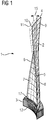
- FIG. 1 the vibration process of the blade 1 is shown after the first vibration mode.
- the first vibration mode is characterized by the lowest frequency natural frequency of the blade 1.
- FIG. 1 shows the blade 1 in its rest position 10 (solid lines) and a deflected blade 11 (dashed lines).
- the vibration process according to the first vibration mode is characterized by a vibration node 12 on the blade root 3.
- the deflection 15 of the blade 1 is at the blade tip 4 maximum.
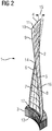
- the vibration process of the blade 1 is shown after the second vibration mode.
- the second vibration mode is the vibration mode with the second lowest natural frequency of the blade 1. Also shown is the rest position 10 (solid lines) of the blade 1 and a deflected blade 11 (dashed lines).
- the oscillation process according to the second oscillation mode is characterized by two oscillation nodes, namely a first oscillation node 12 on the blade root 3 and a second oscillation node 14, which is arranged radially slightly outside the center of the airfoil 2 in the radial direction. Between the first vibration node 13 and the second vibration node 14, a vibration belly 16 is formed.
- the first and second modes of vibration are the dominant modes of vibration.
- the deflected blades 11 off FIGS. 1 and 2 are recorded at the same time of the oscillation process.
- the voltages of the first and second modes of vibration result in a superposition of the two modes of vibration at least partial cancellation of the stresses on the leading edge 5 and / or at the trailing edge 6 in the region of the blade root 3.
- the leading edge 5 and the trailing edge 6 in the region of the blade root 3 are the locations of the blade 1, which in a vibration process are the strongest voltage, ie it is here the life-sustaining locations 17 of the blade. 1
- the procedure for laying out the blade 1 is to be carried out as follows: determining a blade geometry and material properties of the blade 1; Defining the vibration excitation at the blade root 3 of the blade 1 as a periodically occurring tangential graspstraddling as a boundary condition and computationally determining the vibration excitation following vibration process of the blade 1 by a finite element 9 method, being specified as a further boundary condition of the blade root as a fixed end; Determining modal coordinates by decomposing the oscillation process into the ten lowest frequency oscillation modes; Calculating modal stress tensors of the blade 1 for each of the two lowest frequency vibration modes; Calculating stress tensors from the modal coordinates and the modal stress tensors of the two lowest frequency vibration modes; Modifying the blade geometry and / or the material properties such that the natural frequencies of the two low-frequency vibration modes are changed so that the voltages of the stress tensors on the blade root 3 of the blade 1 are lower than the voltages of the stress tensors on the blade
Landscapes
- Engineering & Computer Science (AREA)
- Mechanical Engineering (AREA)
- General Engineering & Computer Science (AREA)
- Turbine Rotor Nozzle Sealing (AREA)
Priority Applications (1)
| Application Number | Priority Date | Filing Date | Title |
|---|---|---|---|
| EP12153627.0A EP2623716A1 (fr) | 2012-02-02 | 2012-02-02 | Procédé de dimensionnement d'une aube directrice |
Applications Claiming Priority (1)
| Application Number | Priority Date | Filing Date | Title |
|---|---|---|---|
| EP12153627.0A EP2623716A1 (fr) | 2012-02-02 | 2012-02-02 | Procédé de dimensionnement d'une aube directrice |
Publications (1)
| Publication Number | Publication Date |
|---|---|
| EP2623716A1 true EP2623716A1 (fr) | 2013-08-07 |
Family
ID=45560769
Family Applications (1)
| Application Number | Title | Priority Date | Filing Date |
|---|---|---|---|
| EP12153627.0A Withdrawn EP2623716A1 (fr) | 2012-02-02 | 2012-02-02 | Procédé de dimensionnement d'une aube directrice |
Country Status (1)
| Country | Link |
|---|---|
| EP (1) | EP2623716A1 (fr) |
Cited By (1)
| Publication number | Priority date | Publication date | Assignee | Title |
|---|---|---|---|---|
| CN116122914A (zh) * | 2023-03-07 | 2023-05-16 | 西安热工研究院有限公司 | 一种适用于深度调峰的叶片倒角与端壁设计方法 |
Citations (1)
| Publication number | Priority date | Publication date | Assignee | Title |
|---|---|---|---|---|
| EP1528223A2 (fr) * | 2003-10-29 | 2005-05-04 | ROLLS-ROYCE plc | Etude des aubes de turbomachines soumises aux vibrations |
-
2012
- 2012-02-02 EP EP12153627.0A patent/EP2623716A1/fr not_active Withdrawn
Patent Citations (1)
| Publication number | Priority date | Publication date | Assignee | Title |
|---|---|---|---|---|
| EP1528223A2 (fr) * | 2003-10-29 | 2005-05-04 | ROLLS-ROYCE plc | Etude des aubes de turbomachines soumises aux vibrations |
Non-Patent Citations (1)
| Title |
|---|
| PANNING ET AL: "Auslegung von Reibelementen zur Schwingungsdampfung von Turbinenschaufeln", DISSERTATION UNIVERSITÄT HANNOVER,, 1 January 2005 (2005-01-01), pages 1 - 226, XP007921084 * |
Cited By (1)
| Publication number | Priority date | Publication date | Assignee | Title |
|---|---|---|---|---|
| CN116122914A (zh) * | 2023-03-07 | 2023-05-16 | 西安热工研究院有限公司 | 一种适用于深度调峰的叶片倒角与端壁设计方法 |
Similar Documents
| Publication | Publication Date | Title |
|---|---|---|
| DE102011054589B4 (de) | Rotationsmaschine mit Abstandhaltern zur Steuerung der Fluiddynamik | |
| EP1853795B1 (fr) | Procédé d'usinage d'un rotor à aubage intégré | |
| EP2603669B1 (fr) | Agencement d'aubes et turbine à gaz associée | |
| CH708644A2 (de) | Skalierungsverfahren für kundenspezifisch dimensionierte Turbomaschinenschaufelblätter. | |
| DE3413162A1 (de) | Schaufelrad mit verminderter schaufelfussbeanspruchung | |
| DE102007019907A1 (de) | Vorrichtung zur aktiven Dämpfung eines Triebstrangs bei einer Windenergieanlage | |
| EP3088663A1 (fr) | Procédé de profilage d'une aube | |
| EP3428396A1 (fr) | Procédé de génération et de choix d'un modèle de désaccord d'une roue d'une turbomachine comportant une pluralité de pales tournantes | |
| EP2805017B1 (fr) | Stator pour une turbomachine axiale et procédé de dimensionnement du stator | |
| EP2786471B1 (fr) | Procédé pour faire fonctionner un moteur électrique | |
| EP2617945A1 (fr) | Rotor pour une turbomachine | |
| DE102012024273A1 (de) | Verfahren zum Abstimmen belastungsabhängiger Prozesse bei Windenergieanlagen und Mittel zu dessen Implementierung | |
| EP2623716A1 (fr) | Procédé de dimensionnement d'une aube directrice | |
| EP2550732A2 (fr) | Évitement de la production de torsion dans des trains de compresseurs commandés par convertisseurs | |
| EP2912272B1 (fr) | Procédé de désaccordage d'une matrice d'aube directrice | |
| EP2992588B1 (fr) | Stator de générateur synchrone et générateur synchrone | |
| EP2977553A1 (fr) | Grille d'aube desaccordée pour une turbomachine | |
| DE102008004761A1 (de) | Luftturbine für ein Wellenkraftwerk | |
| EP1848876B1 (fr) | Procede pour augmenter la duree de vie en fatigue de l'emplanture d'une aube de turbomachine | |
| WO2008116738A1 (fr) | Turbine à gaz à tirant longitudinal à refroidissement interne | |
| DE102019123277A1 (de) | Verfahren zum Auswuchten von Läufern elektrischer Maschinen | |
| WO2007107134A1 (fr) | Stator comportant un revêtement électro-isolant et procédé de réduction de vibrations | |
| EP2551460A1 (fr) | Groupe d'aubes | |
| EP3303801B1 (fr) | Procédé de couplage de deux arbres partiels | |
| EP1828616B1 (fr) | Méthode d' amélioration de la stabilité de courant d' une turbomachine |
Legal Events
| Date | Code | Title | Description |
|---|---|---|---|
| PUAI | Public reference made under article 153(3) epc to a published international application that has entered the european phase |
Free format text: ORIGINAL CODE: 0009012 |
|
| AK | Designated contracting states |
Kind code of ref document: A1 Designated state(s): AL AT BE BG CH CY CZ DE DK EE ES FI FR GB GR HR HU IE IS IT LI LT LU LV MC MK MT NL NO PL PT RO RS SE SI SK SM TR |
|
| AX | Request for extension of the european patent |
Extension state: BA ME |
|
| STAA | Information on the status of an ep patent application or granted ep patent |
Free format text: STATUS: THE APPLICATION IS DEEMED TO BE WITHDRAWN |
|
| 18D | Application deemed to be withdrawn |
Effective date: 20140208 |