EP2623745B1 - Soupape de retour de carburant de moteur à turbine à gaz - Google Patents
Soupape de retour de carburant de moteur à turbine à gaz Download PDFInfo
- Publication number
- EP2623745B1 EP2623745B1 EP13152110.6A EP13152110A EP2623745B1 EP 2623745 B1 EP2623745 B1 EP 2623745B1 EP 13152110 A EP13152110 A EP 13152110A EP 2623745 B1 EP2623745 B1 EP 2623745B1
- Authority
- EP
- European Patent Office
- Prior art keywords
- fuel
- valve
- return
- flow
- fuel inlet
- Prior art date
- Legal status (The legal status is an assumption and is not a legal conclusion. Google has not performed a legal analysis and makes no representation as to the accuracy of the status listed.)
- Active
Links
Images


Classifications
-
- F—MECHANICAL ENGINEERING; LIGHTING; HEATING; WEAPONS; BLASTING
- F02—COMBUSTION ENGINES; HOT-GAS OR COMBUSTION-PRODUCT ENGINE PLANTS
- F02C—GAS-TURBINE PLANTS; AIR INTAKES FOR JET-PROPULSION PLANTS; CONTROLLING FUEL SUPPLY IN AIR-BREATHING JET-PROPULSION PLANTS
- F02C7/00—Features, components parts, details or accessories, not provided for in, or of interest apart form groups F02C1/00 - F02C6/00; Air intakes for jet-propulsion plants
- F02C7/22—Fuel supply systems
- F02C7/232—Fuel valves; Draining valves or systems
-
- Y—GENERAL TAGGING OF NEW TECHNOLOGICAL DEVELOPMENTS; GENERAL TAGGING OF CROSS-SECTIONAL TECHNOLOGIES SPANNING OVER SEVERAL SECTIONS OF THE IPC; TECHNICAL SUBJECTS COVERED BY FORMER USPC CROSS-REFERENCE ART COLLECTIONS [XRACs] AND DIGESTS
- Y10—TECHNICAL SUBJECTS COVERED BY FORMER USPC
- Y10T—TECHNICAL SUBJECTS COVERED BY FORMER US CLASSIFICATION
- Y10T137/00—Fluid handling
- Y10T137/7287—Liquid level responsive or maintaining systems
-
- Y—GENERAL TAGGING OF NEW TECHNOLOGICAL DEVELOPMENTS; GENERAL TAGGING OF CROSS-SECTIONAL TECHNOLOGIES SPANNING OVER SEVERAL SECTIONS OF THE IPC; TECHNICAL SUBJECTS COVERED BY FORMER USPC CROSS-REFERENCE ART COLLECTIONS [XRACs] AND DIGESTS
- Y10—TECHNICAL SUBJECTS COVERED BY FORMER USPC
- Y10T—TECHNICAL SUBJECTS COVERED BY FORMER US CLASSIFICATION
- Y10T137/00—Fluid handling
- Y10T137/7722—Line condition change responsive valves
- Y10T137/7758—Pilot or servo controlled
- Y10T137/7761—Electrically actuated valve
-
- Y—GENERAL TAGGING OF NEW TECHNOLOGICAL DEVELOPMENTS; GENERAL TAGGING OF CROSS-SECTIONAL TECHNOLOGIES SPANNING OVER SEVERAL SECTIONS OF THE IPC; TECHNICAL SUBJECTS COVERED BY FORMER USPC CROSS-REFERENCE ART COLLECTIONS [XRACs] AND DIGESTS
- Y10—TECHNICAL SUBJECTS COVERED BY FORMER USPC
- Y10T—TECHNICAL SUBJECTS COVERED BY FORMER US CLASSIFICATION
- Y10T137/00—Fluid handling
- Y10T137/7722—Line condition change responsive valves
- Y10T137/7758—Pilot or servo controlled
- Y10T137/7762—Fluid pressure type
- Y10T137/7769—Single acting fluid servo
- Y10T137/777—Spring biased
-
- Y—GENERAL TAGGING OF NEW TECHNOLOGICAL DEVELOPMENTS; GENERAL TAGGING OF CROSS-SECTIONAL TECHNOLOGIES SPANNING OVER SEVERAL SECTIONS OF THE IPC; TECHNICAL SUBJECTS COVERED BY FORMER USPC CROSS-REFERENCE ART COLLECTIONS [XRACs] AND DIGESTS
- Y10—TECHNICAL SUBJECTS COVERED BY FORMER USPC
- Y10T—TECHNICAL SUBJECTS COVERED BY FORMER US CLASSIFICATION
- Y10T137/00—Fluid handling
- Y10T137/8593—Systems
- Y10T137/86493—Multi-way valve unit
- Y10T137/86574—Supply and exhaust
- Y10T137/86582—Pilot-actuated
-
- Y—GENERAL TAGGING OF NEW TECHNOLOGICAL DEVELOPMENTS; GENERAL TAGGING OF CROSS-SECTIONAL TECHNOLOGIES SPANNING OVER SEVERAL SECTIONS OF THE IPC; TECHNICAL SUBJECTS COVERED BY FORMER USPC CROSS-REFERENCE ART COLLECTIONS [XRACs] AND DIGESTS
- Y10—TECHNICAL SUBJECTS COVERED BY FORMER USPC
- Y10T—TECHNICAL SUBJECTS COVERED BY FORMER US CLASSIFICATION
- Y10T137/00—Fluid handling
- Y10T137/8593—Systems
- Y10T137/86493—Multi-way valve unit
- Y10T137/86574—Supply and exhaust
- Y10T137/8667—Reciprocating valve
- Y10T137/86694—Piston valve
- Y10T137/86702—With internal flow passage
-
- Y—GENERAL TAGGING OF NEW TECHNOLOGICAL DEVELOPMENTS; GENERAL TAGGING OF CROSS-SECTIONAL TECHNOLOGIES SPANNING OVER SEVERAL SECTIONS OF THE IPC; TECHNICAL SUBJECTS COVERED BY FORMER USPC CROSS-REFERENCE ART COLLECTIONS [XRACs] AND DIGESTS
- Y10—TECHNICAL SUBJECTS COVERED BY FORMER USPC
- Y10T—TECHNICAL SUBJECTS COVERED BY FORMER US CLASSIFICATION
- Y10T137/00—Fluid handling
- Y10T137/8593—Systems
- Y10T137/86493—Multi-way valve unit
- Y10T137/86815—Multiple inlet with single outlet
Definitions
- the present invention generally relates to gas turbine engine fuel controls, and more particularly relates to a fuel return valve for a gas turbine engine fuel control system.
- fuel is not only supplied to the gas turbine propulsion engines to propel the aircraft, but is also used for thermal management. That is, a portion of the fuel withdrawn from the fuel tanks may also be used to cool various components and lubrication oils, and then returned to the fuel tanks.
- the fuel in the aircraft fuel tanks is typically relatively cool (e.g., ambient temperature), whereas the fuel that has been withdrawn from the fuel tanks, pressurized by one or more pumps, directed through various fuel/oil coolers, equipment cooling circuits, fuel control bypass loops, and the like, is relatively hot (e.g., about 325° F).
- burn flow rate of fuel may also be relatively low.
- the relatively low burn flow rate may cause the fuel that is returned to the fuel tanks to be at a relatively high temperature.
- Regulatory authorities place limits on the temperature of fuel being returned to an aircraft fuel tank.
- some aircraft fuel supply systems include a plurality of valves to selectively mix relatively cool fuel with the relatively hot return fuel to lower its temperature before being returned to the fuel tank(s).
- both the mix of hot and cool fuel flows and the total fuel flow amount are accurately controlled to two different levels.
- the presently known configurations for selectively controlling return fuel flow to a fuel tank are generally safe, reliable, and robust, but do exhibit certain drawbacks.
- these configurations rely on multiple valves, multiple solenoids, and multiple position sensors, which can increase overall system cost and weight.
- EP0391609 discloses a program-controlled heat management system for an aircraft's bypass gas turbine (turbofan) engine installation, in which the engine's fuel system is put into direct heat exchange relationship with the engine's own oil system, and with an engine-driven electrical generator's oil system.
- Turbofan bypass gas turbine
- the invention relates to a fuel return valve according to claim 1.
- the fuel return valve includes a flow-level select and shut-off valve and a servo control valve.
- the flow-level select and shut-off valve includes a first fuel inlet, a second fuel inlet, a return-to-tank fuel outlet, and a valve element movable between a shut-off position, a mid-flow position, and a max-flow position.
- the servo control valve is coupled to the flow-level select and shut-off valve and is configured to control relative fluid pressures therein to selectively move the valve element to the shut-off position, the mid-flow position, and the max-flow position.
- the flow-level select and shut-off valve is configured such that when the valve element is in the shut-off position, fuel is prevented from flowing into and through the first and second fuel inlet ports and out the return-to-tank outlet port.
- fuel may flow into and through the first and second fuel inlets and out the return-to-tank outlet port at a first flow rate.
- fuel may flow into and through the first and second fuel inlets and out the return-to-tank outlet port at a second flow rate that is greater than the first flow rate.
- the servo control valve includes a servo fuel inlet, a servo fuel outlet, a first servo fuel control pressure port, and a second servo fuel control pressure port.
- the servo control valve is configured to selectively control relative fluid pressures at the first and second servo fuel control pressure ports.
- the flow-level select and shut-off valve includes first and second cold fuel inlet ports, first and second hot fuel inlet ports, a return-to-tank outlet port, a control pressure inlet port, a first control pressure port, a second control pressure port, and a valve element movable to at least a shut-off position, a mid-flow position, and a max-flow position.
- the control pressure inlet port is in fluid communication with the servo fuel inlet
- the first control pressure port is coupled to and is in fluid communication with the first servo fuel control pressure port
- the second control pressure port is coupled to and is in fluid communication with the second servo fuel control pressure port.
- the flow-level select and shut-off valve is configured such that the valve element is in the shut-off position when the fluid pressure at the first servo fuel control pressure port is greater than the fluid pressure at the second servo fuel control pressure port, whereby the first and second cold fuel inlet ports and the first and second hot fuel inlet ports are both fluidly isolated from the return-to-tank outlet port.
- the valve element is in the mid-flow position when the fluid pressure at the first servo fuel control pressure port is equal to the fluid pressure at the second servo fuel control pressure port, whereby only the first cold fuel inlet port and only the first hot fuel inlet port are in fluid communication with the return-to-tank outlet port.
- the valve element is in in the max-flow position when the fluid pressure at the first servo fuel control pressure port is less than the fluid pressure at the second servo fuel control pressure port, whereby both the first and second cold fuel inlet ports and both the first and second hot fuel inlet ports are in fluid communication with the return-to-tank outlet port.
- a fuel return flow control system includes a servo control fuel source, a cold fuel return flow source, a hot fuel return flow source, and a fuel return valve in fluid communication with the servo control fuel source, the cold fuel return flow source, and the hot fuel return flow source.
- the fuel return valve includes an electrohydraulic servo control valve and a flow-level select and shut-off valve.
- the electrohydraulic servo control valve includes a servo fuel inlet, a servo fuel outlet, a first servo fuel control pressure port, and a second servo fuel control pressure port.
- the servo fuel inlet is in fluid communication with the servo control fuel source.
- the electrohydraulic servo control valve is configured to selectively control relative fuel pressures at the first and second servo fuel control pressure ports.
- the flow-level select and shut-off valve includes first and second cold fuel inlet ports, first and second hot fuel inlet ports, a return-to-tank fuel outlet port, a control pressure inlet port, a first control pressure port, a second control pressure port, and a valve element movable to at least a shut-off position, a mid-flow position, and a max-flow position.
- the control pressure inlet port is in fluid communication with the servo control fuel source, the first control pressure port is coupled to and is in fluid communication with the first servo fuel control pressure port, the second control pressure port is coupled to and is in fluid communication with the second servo fuel control pressure port, the first and second cold fuel inlet ports are in fluid communication with the cold fuel return flow source, and the first and second hot fuel inlet ports are in fluid communication with the hot fuel return flow source.
- the flow-level select and shut-off valve is configured such that the valve element is in the shut-off position when the fuel pressure at the first servo fuel control pressure port is greater than the fuel pressure at the second servo fuel control pressure port, whereby the first and second cold fuel inlet ports and the first and second hot fuel inlet ports are both fluidly isolated from the return-to-tank fuel outlet port.
- the valve element is in the mid-flow position when the fuel pressure at the first servo fuel control pressure port is equal to the fuel pressure at the second servo fuel control pressure port, whereby only the first cold fuel inlet port and only the first hot fuel inlet port are in fluid communication with the return-to-tank fuel outlet port.
- the valve element is in in the max-flow position when the fuel pressure at the first servo fuel control pressure port is less than the fuel pressure at the second servo fuel control pressure port, whereby both the first and second cold fuel inlet ports and both the first and second hot fuel inlet ports are in fluid communication with the return-to-tank fuel outlet port.
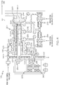
- FIG. 1 a functional block diagram of at least a portion of an embodiment of a fuel return flow control system is depicted, and includes a servo control fuel source 102, a cold fuel return flow source 104, a hot fuel return flow source 106, a fuel return valve (FRV) 108, and a fuel tank 110.
- the servo control fuel source 102, the cold return fuel source 104, and the hot return fuel source 106 are depicted in simplified form in FIG. 1 because the specific location of these sources within an aircraft fuel supply system may vary. It is noted, however, that the cold fuel return source 104 and the hot fuel return source 106 are each in locations where the temperature of the fuel from the cold fuel return flow source 104 is lower than the fuel supplied from the hot fuel return flow source 106.
- the FRV 108 is in fluid communication with each of these source.
- the FRV 108 is also adapted to receive selectively supplied position commands from a non-illustrated source, and is configured, in response to the selectively supplied position commands, to be controllably moved to three different positions - a shut-off position, a mid-flow position, and a max-flow position. As may be appreciated, in the shut-off position, no fuel flows through the FRV 108.
- shut-off and dual-flow metering functionality of the FRV 108 is implemented into a single valve body 112.
- FIGS. 2-4 A particular configuration of the FRV 108 for implementing this functionality is depicted in FIGS. 2-4 , and will now be described.
- the depicted FRV 108 includes a servo control valve 202 and a flow-level select and shut-off valve 204, disposed within the single valve body 112.
- the servo control valve 202 includes a servo fuel inlet 206, which is in fluid communication with the servo control fuel source 102.
- the servo control valve 202 additionally includes a servo fuel outlet 208, a first servo fuel control pressure port 212, and a second servo fuel control pressure port 214.
- the servo control valve 202 is configured, in response to the selectively supplied position commands described above, to selectively control the relative fuel pressures at the first and second servo fuel control pressure ports 212,214.
- the servo control valve 202 may be variously implemented and configured to carry out its functionality, but in the depicted embodiment the servo control valve 202 is implemented using a dual-channel electrohydraulic servo valve (EHSV).
- the EHSV 202 includes a dual-channel torque motor 216 and a jet pipe 218.
- the torque motor 216 includes an armature 222 and two sets of windings 224 (e.g., 224-1, 224-2).
- the armature 222 is coupled to the jet pipe 218, and the windings are each coupled to the source of the selectively supplied position commands. In most embodiments, only one set of the windings 224 will receive a position command, with the other set being a back-up.
- both sets of windings 224 could be simultaneously supplied with a position command.
- the armature 222 is responsive to the supplied position commands to move the jet pipe 218 to one of three discrete positions - a first control position, a second control position, or a third control position.
- the jet pipe 218 includes an inlet port 226 and an outlet port 228.
- the inlet port 226 is in fluid communication with the servo fuel inlet 206, and thus receives a flow of servo fuel supplied from the servo control fuel source 102.
- the outlet port 228 is disposed adjacent the servo fuel outlet 208, the first servo fuel control pressure port 212, and the second servo fuel control pressure port 214, and discharges fuel supplied to the jet pipe 218.
- the jet pipe 218 based on its three discrete positions, establishes three different pressure states at the first and second servo fuel control pressure ports 212, 214. In the first control position, which is the position depicted in FIG.
- pressure at the first servo fuel control pressure port 212 will be higher than the pressure at the second servo fuel control pressure port 214.
- pressures at the first and second servo fuel control pressure ports 212, 214 will be at least substantially equal.
- pressure at the second servo fuel control pressure port 214 will be higher than the pressure at the first servo fuel control pressure port 212.
- the flow-level select and shut-off valve 204 includes a control pressure inlet port 232, a first control pressure port 234, a second control pressure port 236, a first fuel inlet 238, a second fuel inlet 242, a return-to-tank fuel outlet port 244, and a valve element 246.
- the valve element 246 is a multi-diameter valve that includes at least a relatively larger head end 246-1, and a relatively smaller rod end 246-2.
- the rod end 246-2 consists of a double wall to form fluid passageway 246-3.
- the control pressure inlet port 232 supplies pressure to an annular chamber 235, that is defined by the valve body 112, the valve element head end 246-1, and the valve element rod end 246-2.
- the control pressure inlet port 232 is in fluid communication with the servo control fuel source 102 via a flow control orifice 233 and, at least in the depicted embodiment, is also in fluid communication with the servo fuel inlet 206.
- the first control pressure port 234 supplies pressure to a head end chamber 237 that is defined by the valve body 112 and the valve element 246.
- the first control pressure port 234 is coupled to and is in fluid communication with the first servo fuel control pressure port 212.
- the second control pressure port 236 is coupled to and is in fluid communication with the second servo fuel control pressure port 214.
- the first fuel inlet 238 is in fluid communication with the cold fuel return flow source 104
- the second fuel inlet 242 is in fluid communication with the hot fuel return flow source 106
- the return-to-tank fuel outlet port 244 is in fluid communication with the fuel tank 110.
- the valve element 246 is disposed within the valve body 112 and is movable to at least the shut-off position, the mid-flow position, and the max-flow position.
- the shut-off position which is the position depicted in FIG. 2
- fuel is prevented from flowing into and through the first and second fuel inlets 238, 242 and out the return-to-tank outlet port 244.
- the mid-flow position which is the position depicted in FIG. 3
- fuel may flow into and through the first and second fuel inlets 238, 242 and out the return-to-tank outlet port 244 at the first flow rate.
- the max-flow position which is the position depicted in FIG. 4
- fuel may flow into and through the first and second fuel inlets 238, 242 and out the return-to-tank outlet port 244 at the second, greater flow rate.
- the flow-level select and shut-off valve 204 may be variously configured to facilitate the first and second flow rates when the valve element 246 is moved to the mid-flow and max-flow positions, respectively, in the depicted embodiment the valve element 246 has a plurality of ports formed therein. More specifically, the valve element 246 has first and second cold fuel inlet ports 248-1, 248-2 and first and second hot fuel inlet ports 252-1, 252-2. Based on the position of the valve element 246, none, one, or both of the first and second cold fuel inlet ports 248-1, 248-2 may be selectively placed in fluid communication with the first fuel inlet 238 and the return-to-tank outlet port 244.
- first and second hot fuel inlet ports 252-1, 252-2 may be selectively placed in fluid communication with the second fuel inlet 242 and the return-to-tank outlet port 244, based on the position of the valve element 246.
- the first and second cold fuel inlet ports 248-1, 248-2 are both fluidly isolated from the first fuel inlet 238 and the return-to-tank outlet port 244, and the first and second hot fuel inlet ports 252-1, 252-2 are both fluidly isolated from the second fuel inlet 242 and the return-to-tank outlet port 244.
- the first and second cold fuel inlet ports 248-1, 248-2 are both fluidly isolated from the first fuel inlet 238 and the return-to-tank outlet port 244
- the first and second hot fuel inlet ports 252-1, 252-2 are both fluidly isolated from the second fuel inlet 242 and the return-to-tank outlet port 244.
- both the first and second cold fuel inlet ports 248-1, 248-2 are in fluid communication with the first fuel inlet 238 and the return-to-tank outlet port 244 via fluid passageway 246-3, and both the first and second hot fuel inlet ports 252-1, 252-2 are in fluid communication with the second fuel inlet 242 and the return-to-tank outlet port 244 via fluid passageway 246-3.
- the flow-level select and shut-off valve 204 is positioned in response to the three different pressure states that are established at the first and second servo fuel control pressure ports 212, 214 of the servo valve 202. A more detailed discussion of how this takes place will now be provided. With reference once again to FIG. 2 , which depicts the jet pipe 218 in the first control position, pressure at the first servo fuel control pressure port 212 is higher than the pressure at the second servo fuel control pressure port 214. As a result, pressure at the first control pressure port 234 is higher than the pressure at the second control pressure port 236.
- the pressure at the second control pressure port 236 is now higher than the pressure at the first control pressure port 234. This results in a relatively low pressure in head end chamber 237 acting on the valve element head end 246-1, a relatively high pressure acting on the annular area of valve element 246, and a relatively low pressure acting on the valve element rod end 246-2. This pressure state causes the valve element 246 to move to the max-flow position.
- the servo valve 202 configured such that the jet pipe 218 will move to the second control position whenever the torque motor 216 is deenergized. This ensures the FRV 108 will be moved to the mid-flow position in the unlikely event electrical power to the FRV 108 is unavailable. This is sometimes referred to as a "Fail Safe" position.
- the depicted FRV 108 additionally includes a first fuel pressure regulator valve 254, a second fuel pressure regulator valve 256, and a valve position sensor 258.
- the first fuel pressure regulator 254 is disposed upstream of the first fuel inlet 238, and the second fuel pressure regulator valve 256 is disposed upstream of the second fuel inlet 242.
- the first and second fuel pressure regulators 254, 256 are independent, and control the differential pressures across the first and second cold fuel inlet ports 248-1, 248-2 and the first and second hot fuel inlet ports 252-1, 252-2, respectively. This ensures accurate flows over a large range of pressures upstream from the pressure regulator valves.
- the valve position sensor 258 is configured to sense the position of the FRV 108, and more specifically the valve element 246, and supply a valve position signal representative thereof.
- the valve position sensor 258 may be implemented using any one of numerous of position sensing devices, in the depicted embodiment it is implemented using a linear variable differential transformer (LVDT) position sensor.
- the valve position sensor 258 thus includes an outer housing 262 and a movable slug 264.
- the outer housing 262 is coupled to the valve body 112 and extends into the valve element 246, and houses a non-illustrated LVDT.
- the movable slug 264 engages the valve element 246, and is partially disposed within and is movable relative to the outer housing 262.
- a spring element 266 is provided in the depicted embodiment to load the movable slug 264 into engagement against the valve element 246, alleviating the need to fasten, weld, braze, or otherwise couple the movable slug 264 to the valve element 246.
- the spring element 266 also supplies a bias force to the valve element 246 that urges the valve element 246 against the seat 268 when no servo control fluid pressure is supplied to the FRV 108, such as during engine shutdown conditions. This ensures very little or no leakage through the FRV 108 to the fuel tank 110 when the engine is shut down. It should be noted that the spring element 266 is not relied upon to position the valve element 246, to any one of the three discrete positions during normal engine operational modes when servo fluid pressure is being supplied to the FRV 108.
- the FRV 108 disclosed herein implements accurate metering and shut-off functions into a single valve with a single position sensor.
- the FRV 108 can be commanded to three discrete positions, using a relatively simple single stage servo valve that is commanded to three respective discrete positions, and does not rely on positioning springs or complex closed loop control logic during normal engine operating conditions.
Landscapes
- Engineering & Computer Science (AREA)
- Chemical & Material Sciences (AREA)
- Combustion & Propulsion (AREA)
- Mechanical Engineering (AREA)
- General Engineering & Computer Science (AREA)
- Multiple-Way Valves (AREA)
- Fuel-Injection Apparatus (AREA)
- Fluid-Driven Valves (AREA)
Claims (8)
- Soupape de retour de carburant, comprenant :une soupape d'arrêt et de sélection de niveau de débit (204), comportant un orifice d'entrée de pression de commande (232), un premier orifice de pression de commande (234), un second orifice de pression de commande (236), une première entrée de carburant (238), une seconde entrée de carburant (242), une sortie de carburant de retour au réservoir (244) et un élément de soupape (246) mobile entre une position d'arrêt, une position de débit moyen et une position de débit maximum ; etune soupape de servocommande (202) accouplée à la soupape d'arrêt et de sélection de niveau de débit (204) et conçue pour y commander des pressions de fluide relatives pour déplacer de manière sélective l'élément de soupape (246) dans la position d'arrêt, la position de débit moyen et la position de débit maximum,la soupape d'arrêt et de sélection de niveau de débit (204) étant conçue de sorte que :quand l'élément de soupape (246) est dans la position d'arrêt, le carburant est empêché d'entrer par les premier et second orifices d'entrée de carburant (238, 242) et de sortir par l'orifice de sortie de retour au réservoir (244),quand l'élément de soupape (246) est dans la position de débit moyen, le carburant entre par les première et seconde entrées de carburant (238, 242) et sort par l'orifice de sortie de retour au réservoir (244) à un premier débit, etquand l'élément de soupape (246) est dans la position de débit maximum, le carburant peut entrer par les première et seconde entrées de carburant (238, 242) et sortir par l'orifice de sortie de retour au réservoir (244) à un second débit qui est supérieur au premier débit.
- Soupape de retour de carburant selon la revendication 1, dans laquelle la soupape de servocommande comprend :une entrée de carburant asservie (206) ;une sortie de carburant asservie (208) ;un premier orifice de pression de commande de carburant asservi (212) ; etun second orifice de pression de commande de carburant asservi (214),la soupape de servocommande (202) étant conçue pour commander de manière sélective des pressions de fluide relatives dans la soupape d'arrêt et de sélection de niveau de débit (204) en commandant des pressions de fluide relatives au niveau des premier et second orifices de pression de commande de carburant asservis (212, 214).
- Soupape de retour de carburant selon la revendication 1, dans laquelle la soupape de servocommande (202) est une servovalve électrohydraulique (EHSV).
- Soupape de retour de carburant selon la revendication 1, dans laquelle l'élément de soupape (246) comprend :des premier et second orifices d'entrée de carburant froid (248-1, 248-2), le premier et/ou le second orifice d'entrée de carburant froid étant placés de manière sélective en communication fluidique avec la première entrée de carburant (238) et l'orifice de sortie de retour au réservoir (244), sur la base de la position de l'élément de soupape (246) ; etdes premier et second orifices d'entrée de carburant chaud (252-1, 252-2), le premier et/ou le second orifice d'entrée de carburant chaud étant placés de manière sélective en communication fluidique avec la première entrée de carburant (238) et l'orifice de sortie de retour au réservoir (244), sur la base de la position de l'élément de soupape (246).
- Soupape de retour de carburant selon la revendication 4, dans laquelle :quand l'élément de soupape (246) est dans la position d'arrêt, les premier et second orifices d'entrée de carburant froid (248-1, 248-2) sont l'un et l'autre isolés fluidiquement de la première entrée de carburant (238) et de l'orifice de sortie de retour au réservoir (244), et les premier et second orifices d'entrée de carburant chaud (252-1, 252-2) sont l'un et l'autre isolés fluidiquement de la seconde entrée de carburant (242) et de l'orifice de sortie de retour au réservoir (244) ;quand l'élément de soupape (246) est dans la position de débit moyen, seul le premier orifice d'entrée de carburant froid (248-1) est en communication fluidique avec la première entrée de carburant (238) et l'orifice de sortie de retour au réservoir (244), et seul le premier orifice d'entrée de carburant chaud (252-1) est en communication fluidique avec la seconde entrée de carburant (242) et l'orifice de sortie de retour au réservoir (244) ; etquand l'élément de soupape (246) est dans la position de débit maximum, les premier et second orifices d'entrée de carburant froid (248-1, 248-2) sont l'un et l'autre en communication fluidique avec la première entrée de carburant (238) et l'orifice de sortie de retour au réservoir (244), et les premier et second orifices d'entrée de carburant chaud (252-1, 252-2) sont l'un et l'autre en communication fluidique avec la seconde entrée de carburant (242) et l'orifice de sortie de retour au réservoir (244).
- Soupape de retour de carburant selon la revendication 1, comprenant en outre :un capteur de position (258) accouplé à la soupape d'arrêt et de sélection de niveau de débit (204) et conçu pour en détecter une position.
- Soupape de retour de carburant selon la revendication 6, dans laquelle le capteur de position (258) comprend un transformateur différentiel à variable linéaire (LVDT).
- Soupape de retour de carburant selon la revendication 1, comprenant en outre :une première soupape de régulation de pression de carburant (254) disposée en amont de la première entrée de carburant (238) ; etune seconde soupape de régulation de pression de carburant (256) disposée en amont de la seconde entrée de carburant (242).
Applications Claiming Priority (1)
| Application Number | Priority Date | Filing Date | Title |
|---|---|---|---|
| US13/364,895 US8800594B2 (en) | 2012-02-02 | 2012-02-02 | Gas turbine engine fuel return valve and system |
Publications (3)
| Publication Number | Publication Date |
|---|---|
| EP2623745A2 EP2623745A2 (fr) | 2013-08-07 |
| EP2623745A3 EP2623745A3 (fr) | 2018-04-04 |
| EP2623745B1 true EP2623745B1 (fr) | 2019-03-13 |
Family
ID=47598715
Family Applications (1)
| Application Number | Title | Priority Date | Filing Date |
|---|---|---|---|
| EP13152110.6A Active EP2623745B1 (fr) | 2012-02-02 | 2013-01-21 | Soupape de retour de carburant de moteur à turbine à gaz |
Country Status (3)
| Country | Link |
|---|---|
| US (1) | US8800594B2 (fr) |
| EP (1) | EP2623745B1 (fr) |
| CN (1) | CN103244278B (fr) |
Families Citing this family (4)
| Publication number | Priority date | Publication date | Assignee | Title |
|---|---|---|---|---|
| US9207688B2 (en) * | 2012-10-18 | 2015-12-08 | Hamilton Sundstrand Corporation | Aircraft bleed system and method of controlling an aircraft bleed system |
| GB201419607D0 (en) * | 2014-11-04 | 2014-12-17 | Delphi International Operations Luxembourg S.�.R.L. | Fuel delivery system |
| EP3176443B1 (fr) | 2015-12-01 | 2020-05-06 | Claverham Limited | Soupape hydraulique |
| KR102311668B1 (ko) * | 2017-09-21 | 2021-10-13 | 현대자동차주식회사 | 이종연료탱크용 선택적 연료조절장치 |
Family Cites Families (22)
| Publication number | Priority date | Publication date | Assignee | Title |
|---|---|---|---|---|
| US3010438A (en) * | 1957-05-27 | 1961-11-28 | Fife | Pneumatic control valve for hydraulic system |
| GB1516986A (en) | 1974-10-26 | 1978-07-05 | Lucas Industries Ltd | Fuel control system for a gas turbine engine |
| US4117765A (en) | 1976-12-09 | 1978-10-03 | United Technologies Corporation | Power servo control |
| US4476893A (en) * | 1980-07-04 | 1984-10-16 | Barmag Barmer Maschinenfabrik Ag | Hydraulic flow control valve |
| US4776536A (en) | 1987-05-19 | 1988-10-11 | Rockwell International Corporation | Integrated aircraft fuel thermal management system |
| WO1989005407A1 (fr) * | 1987-12-02 | 1989-06-15 | Ebara Research Co., Ltd | Servovanne hydraulique |
| GB8906060D0 (en) * | 1989-03-16 | 1989-07-05 | Lucas Ind Plc | Gas turbine engine fuel control system,and metering valve therefor |
| GB8907788D0 (en) * | 1989-04-06 | 1989-05-17 | Rolls Royce Plc | Management of heat generated by aircraft gas turbine installations |
| US5735117A (en) | 1995-08-18 | 1998-04-07 | Fuel Systems Textron, Inc. | Staged fuel injection system with shuttle valve and fuel injector therefor |
| US5772182A (en) * | 1996-04-17 | 1998-06-30 | United Technologies Corporation | Fuel flow control valve |
| GB9619488D0 (en) | 1996-09-18 | 1996-10-30 | Dowty Boulton Paul Ltd | Flight control surface actuation system |
| GB9723466D0 (en) * | 1997-11-07 | 1998-01-07 | Lucas Ind Plc | Fluid flow valve and fluid flow system |
| US6102001A (en) | 1998-12-04 | 2000-08-15 | Woodward Governor Company | Variable displacement pump fuel metering system and electrohydraulic servo-valve for controlling the same |
| WO2001020148A2 (fr) | 1999-08-20 | 2001-03-22 | Siemens Westinghouse Power Corporation | Systeme et procedes permettant de commander une turbine a gaz faisant intervenir des pompes a combustible liquide a vitesse variable a elements couples |
| DE60129185T2 (de) | 2000-05-12 | 2008-03-13 | Goodrich Control Systems Ltd., Luton | Überwachungsanordnung um den Zustand eines Ventils in einem Kraftstoffzufuhrsystem feststellen zu können |
| US6682016B1 (en) | 2002-09-05 | 2004-01-27 | Hamilton Sundstrand | Thermal management valve with drop-tight shutoff of return to tank |
| US7607285B2 (en) | 2003-08-01 | 2009-10-27 | Honeywell International Inc. | Four mode thermal recirculation throttle valve |
| US7290565B2 (en) * | 2004-12-02 | 2007-11-06 | Hr Textron, Inc. | Methods and apparatus for splitting and directing a pressurized fluid jet within a servovalve |
| US7779811B1 (en) | 2006-09-13 | 2010-08-24 | General Electric Company | Thermoelectrically cooled components for distributed electronics control system for gas turbine engines |
| US8046983B2 (en) * | 2008-09-11 | 2011-11-01 | Honeywell International Inc. | Ecology valve fuel return system for gas turbine engine |
| US8122699B2 (en) | 2008-12-03 | 2012-02-28 | Honeywell International Inc. | Ecology valve fuel return system operable in fluid isolation during gas turbine engine shut-down |
| US8192172B2 (en) | 2009-04-06 | 2012-06-05 | Woodward, Inc. | Flow sensing shutoff valve |
-
2012
- 2012-02-02 US US13/364,895 patent/US8800594B2/en active Active
-
2013
- 2013-01-21 EP EP13152110.6A patent/EP2623745B1/fr active Active
- 2013-02-01 CN CN201310044107.1A patent/CN103244278B/zh active Active
Non-Patent Citations (1)
| Title |
|---|
| None * |
Also Published As
| Publication number | Publication date |
|---|---|
| US8800594B2 (en) | 2014-08-12 |
| US20130199630A1 (en) | 2013-08-08 |
| EP2623745A3 (fr) | 2018-04-04 |
| EP2623745A2 (fr) | 2013-08-07 |
| CN103244278B (zh) | 2016-06-29 |
| CN103244278A (zh) | 2013-08-14 |
Similar Documents
| Publication | Publication Date | Title |
|---|---|---|
| CA2808588C (fr) | Systeme de communication a double pompe solidaire et proportionnel | |
| US6810674B2 (en) | Fuel delivery system | |
| US9702301B2 (en) | Fuel circuit for an aviation turbine engine, the circuit having a fuel pressure regulator valve | |
| US7784487B2 (en) | Fuel metering valve assembly including thermal compensation mechanism | |
| US7966995B2 (en) | Dual level pressurization control based on fuel flow to one or more gas turbine engine secondary fuel loads | |
| EP2423488A2 (fr) | Système de prélèvement d'air actionné par carburant | |
| CN107074374B (zh) | 用于流体分配系统的泵权限切换装置 | |
| CN104364497B (zh) | 涡轮引擎中的流体回路 | |
| EP2535644B1 (fr) | Systèmes de commande de carburant de chambre de combustion avec ensemble répartiteur d'écoulement | |
| US20090031821A1 (en) | Dual mode compensation for variable displacement pump fluid metering system | |
| EP2623745B1 (fr) | Soupape de retour de carburant de moteur à turbine à gaz | |
| EP2025901B1 (fr) | Système de dosage de carburant avec une introduction de chaleur minimale | |
| JP2006085715A (ja) | 流体の圧力および温度を制御するためのシステムおよび方法 | |
| US12435715B2 (en) | Direct controlled variable displacement pumps with thermostatically controlled bypass | |
| EP4530457A1 (fr) | Système de pompe à carburant à double déplacement variable avec dérivation de refroidissement | |
| WO2015124909A1 (fr) | Système d'alimentation en carburant amélioré pour une turbine à gaz | |
| EP3643953B1 (fr) | Soupape de fluide de refroidissement activée par un incendie | |
| RU2583175C2 (ru) | Гидравлическое оборудование для арматуры, предназначенной для добычи и транспорта преимущественно ископаемого топлива |
Legal Events
| Date | Code | Title | Description |
|---|---|---|---|
| PUAI | Public reference made under article 153(3) epc to a published international application that has entered the european phase |
Free format text: ORIGINAL CODE: 0009012 |
|
| 17P | Request for examination filed |
Effective date: 20130121 |
|
| AK | Designated contracting states |
Kind code of ref document: A2 Designated state(s): AL AT BE BG CH CY CZ DE DK EE ES FI FR GB GR HR HU IE IS IT LI LT LU LV MC MK MT NL NO PL PT RO RS SE SI SK SM TR |
|
| AX | Request for extension of the european patent |
Extension state: BA ME |
|
| RAP1 | Party data changed (applicant data changed or rights of an application transferred) |
Owner name: HONEYWELL INTERNATIONAL INC. |
|
| PUAL | Search report despatched |
Free format text: ORIGINAL CODE: 0009013 |
|
| STAA | Information on the status of an ep patent application or granted ep patent |
Free format text: STATUS: EXAMINATION IS IN PROGRESS |
|
| AK | Designated contracting states |
Kind code of ref document: A3 Designated state(s): AL AT BE BG CH CY CZ DE DK EE ES FI FR GB GR HR HU IE IS IT LI LT LU LV MC MK MT NL NO PL PT RO RS SE SI SK SM TR |
|
| AX | Request for extension of the european patent |
Extension state: BA ME |
|
| RIC1 | Information provided on ipc code assigned before grant |
Ipc: F02C 7/232 20060101AFI20180223BHEP |
|
| 17Q | First examination report despatched |
Effective date: 20180313 |
|
| GRAP | Despatch of communication of intention to grant a patent |
Free format text: ORIGINAL CODE: EPIDOSNIGR1 |
|
| STAA | Information on the status of an ep patent application or granted ep patent |
Free format text: STATUS: GRANT OF PATENT IS INTENDED |
|
| INTG | Intention to grant announced |
Effective date: 20180724 |
|
| RIN1 | Information on inventor provided before grant (corrected) |
Inventor name: FUTA, PAUL Inventor name: PORTOLESE, LARRY Inventor name: LEWIS, STEVEN ALAN |
|
| GRAS | Grant fee paid |
Free format text: ORIGINAL CODE: EPIDOSNIGR3 |
|
| GRAA | (expected) grant |
Free format text: ORIGINAL CODE: 0009210 |
|
| STAA | Information on the status of an ep patent application or granted ep patent |
Free format text: STATUS: THE PATENT HAS BEEN GRANTED |
|
| AK | Designated contracting states |
Kind code of ref document: B1 Designated state(s): AL AT BE BG CH CY CZ DE DK EE ES FI FR GB GR HR HU IE IS IT LI LT LU LV MC MK MT NL NO PL PT RO RS SE SI SK SM TR |
|
| REG | Reference to a national code |
Ref country code: GB Ref legal event code: FG4D |
|
| REG | Reference to a national code |
Ref country code: CH Ref legal event code: EP Ref country code: AT Ref legal event code: REF Ref document number: 1107998 Country of ref document: AT Kind code of ref document: T Effective date: 20190315 |
|
| REG | Reference to a national code |
Ref country code: DE Ref legal event code: R096 Ref document number: 602013052126 Country of ref document: DE |
|
| REG | Reference to a national code |
Ref country code: IE Ref legal event code: FG4D |
|
| REG | Reference to a national code |
Ref country code: NL Ref legal event code: MP Effective date: 20190313 |
|
| REG | Reference to a national code |
Ref country code: LT Ref legal event code: MG4D |
|
| PG25 | Lapsed in a contracting state [announced via postgrant information from national office to epo] |
Ref country code: NO Free format text: LAPSE BECAUSE OF FAILURE TO SUBMIT A TRANSLATION OF THE DESCRIPTION OR TO PAY THE FEE WITHIN THE PRESCRIBED TIME-LIMIT Effective date: 20190613 Ref country code: FI Free format text: LAPSE BECAUSE OF FAILURE TO SUBMIT A TRANSLATION OF THE DESCRIPTION OR TO PAY THE FEE WITHIN THE PRESCRIBED TIME-LIMIT Effective date: 20190313 Ref country code: SE Free format text: LAPSE BECAUSE OF FAILURE TO SUBMIT A TRANSLATION OF THE DESCRIPTION OR TO PAY THE FEE WITHIN THE PRESCRIBED TIME-LIMIT Effective date: 20190313 Ref country code: LT Free format text: LAPSE BECAUSE OF FAILURE TO SUBMIT A TRANSLATION OF THE DESCRIPTION OR TO PAY THE FEE WITHIN THE PRESCRIBED TIME-LIMIT Effective date: 20190313 |
|
| PG25 | Lapsed in a contracting state [announced via postgrant information from national office to epo] |
Ref country code: HR Free format text: LAPSE BECAUSE OF FAILURE TO SUBMIT A TRANSLATION OF THE DESCRIPTION OR TO PAY THE FEE WITHIN THE PRESCRIBED TIME-LIMIT Effective date: 20190313 Ref country code: NL Free format text: LAPSE BECAUSE OF FAILURE TO SUBMIT A TRANSLATION OF THE DESCRIPTION OR TO PAY THE FEE WITHIN THE PRESCRIBED TIME-LIMIT Effective date: 20190313 Ref country code: LV Free format text: LAPSE BECAUSE OF FAILURE TO SUBMIT A TRANSLATION OF THE DESCRIPTION OR TO PAY THE FEE WITHIN THE PRESCRIBED TIME-LIMIT Effective date: 20190313 Ref country code: GR Free format text: LAPSE BECAUSE OF FAILURE TO SUBMIT A TRANSLATION OF THE DESCRIPTION OR TO PAY THE FEE WITHIN THE PRESCRIBED TIME-LIMIT Effective date: 20190614 Ref country code: RS Free format text: LAPSE BECAUSE OF FAILURE TO SUBMIT A TRANSLATION OF THE DESCRIPTION OR TO PAY THE FEE WITHIN THE PRESCRIBED TIME-LIMIT Effective date: 20190313 Ref country code: BG Free format text: LAPSE BECAUSE OF FAILURE TO SUBMIT A TRANSLATION OF THE DESCRIPTION OR TO PAY THE FEE WITHIN THE PRESCRIBED TIME-LIMIT Effective date: 20190613 |
|
| REG | Reference to a national code |
Ref country code: AT Ref legal event code: MK05 Ref document number: 1107998 Country of ref document: AT Kind code of ref document: T Effective date: 20190313 |
|
| PG25 | Lapsed in a contracting state [announced via postgrant information from national office to epo] |
Ref country code: EE Free format text: LAPSE BECAUSE OF FAILURE TO SUBMIT A TRANSLATION OF THE DESCRIPTION OR TO PAY THE FEE WITHIN THE PRESCRIBED TIME-LIMIT Effective date: 20190313 Ref country code: RO Free format text: LAPSE BECAUSE OF FAILURE TO SUBMIT A TRANSLATION OF THE DESCRIPTION OR TO PAY THE FEE WITHIN THE PRESCRIBED TIME-LIMIT Effective date: 20190313 Ref country code: IT Free format text: LAPSE BECAUSE OF FAILURE TO SUBMIT A TRANSLATION OF THE DESCRIPTION OR TO PAY THE FEE WITHIN THE PRESCRIBED TIME-LIMIT Effective date: 20190313 Ref country code: CZ Free format text: LAPSE BECAUSE OF FAILURE TO SUBMIT A TRANSLATION OF THE DESCRIPTION OR TO PAY THE FEE WITHIN THE PRESCRIBED TIME-LIMIT Effective date: 20190313 Ref country code: AL Free format text: LAPSE BECAUSE OF FAILURE TO SUBMIT A TRANSLATION OF THE DESCRIPTION OR TO PAY THE FEE WITHIN THE PRESCRIBED TIME-LIMIT Effective date: 20190313 Ref country code: ES Free format text: LAPSE BECAUSE OF FAILURE TO SUBMIT A TRANSLATION OF THE DESCRIPTION OR TO PAY THE FEE WITHIN THE PRESCRIBED TIME-LIMIT Effective date: 20190313 Ref country code: SK Free format text: LAPSE BECAUSE OF FAILURE TO SUBMIT A TRANSLATION OF THE DESCRIPTION OR TO PAY THE FEE WITHIN THE PRESCRIBED TIME-LIMIT Effective date: 20190313 Ref country code: PT Free format text: LAPSE BECAUSE OF FAILURE TO SUBMIT A TRANSLATION OF THE DESCRIPTION OR TO PAY THE FEE WITHIN THE PRESCRIBED TIME-LIMIT Effective date: 20190713 |
|
| PG25 | Lapsed in a contracting state [announced via postgrant information from national office to epo] |
Ref country code: PL Free format text: LAPSE BECAUSE OF FAILURE TO SUBMIT A TRANSLATION OF THE DESCRIPTION OR TO PAY THE FEE WITHIN THE PRESCRIBED TIME-LIMIT Effective date: 20190313 Ref country code: SM Free format text: LAPSE BECAUSE OF FAILURE TO SUBMIT A TRANSLATION OF THE DESCRIPTION OR TO PAY THE FEE WITHIN THE PRESCRIBED TIME-LIMIT Effective date: 20190313 |
|
| REG | Reference to a national code |
Ref country code: DE Ref legal event code: R097 Ref document number: 602013052126 Country of ref document: DE |
|
| PG25 | Lapsed in a contracting state [announced via postgrant information from national office to epo] |
Ref country code: AT Free format text: LAPSE BECAUSE OF FAILURE TO SUBMIT A TRANSLATION OF THE DESCRIPTION OR TO PAY THE FEE WITHIN THE PRESCRIBED TIME-LIMIT Effective date: 20190313 Ref country code: IS Free format text: LAPSE BECAUSE OF FAILURE TO SUBMIT A TRANSLATION OF THE DESCRIPTION OR TO PAY THE FEE WITHIN THE PRESCRIBED TIME-LIMIT Effective date: 20190713 |
|
| PLBE | No opposition filed within time limit |
Free format text: ORIGINAL CODE: 0009261 |
|
| STAA | Information on the status of an ep patent application or granted ep patent |
Free format text: STATUS: NO OPPOSITION FILED WITHIN TIME LIMIT |
|
| PG25 | Lapsed in a contracting state [announced via postgrant information from national office to epo] |
Ref country code: DK Free format text: LAPSE BECAUSE OF FAILURE TO SUBMIT A TRANSLATION OF THE DESCRIPTION OR TO PAY THE FEE WITHIN THE PRESCRIBED TIME-LIMIT Effective date: 20190313 |
|
| 26N | No opposition filed |
Effective date: 20191216 |
|
| PG25 | Lapsed in a contracting state [announced via postgrant information from national office to epo] |
Ref country code: SI Free format text: LAPSE BECAUSE OF FAILURE TO SUBMIT A TRANSLATION OF THE DESCRIPTION OR TO PAY THE FEE WITHIN THE PRESCRIBED TIME-LIMIT Effective date: 20190313 |
|
| PG25 | Lapsed in a contracting state [announced via postgrant information from national office to epo] |
Ref country code: TR Free format text: LAPSE BECAUSE OF FAILURE TO SUBMIT A TRANSLATION OF THE DESCRIPTION OR TO PAY THE FEE WITHIN THE PRESCRIBED TIME-LIMIT Effective date: 20190313 |
|
| PG25 | Lapsed in a contracting state [announced via postgrant information from national office to epo] |
Ref country code: MC Free format text: LAPSE BECAUSE OF FAILURE TO SUBMIT A TRANSLATION OF THE DESCRIPTION OR TO PAY THE FEE WITHIN THE PRESCRIBED TIME-LIMIT Effective date: 20190313 |
|
| REG | Reference to a national code |
Ref country code: CH Ref legal event code: PL |
|
| REG | Reference to a national code |
Ref country code: BE Ref legal event code: MM Effective date: 20200131 |
|
| PG25 | Lapsed in a contracting state [announced via postgrant information from national office to epo] |
Ref country code: LU Free format text: LAPSE BECAUSE OF NON-PAYMENT OF DUE FEES Effective date: 20200121 |
|
| PG25 | Lapsed in a contracting state [announced via postgrant information from national office to epo] |
Ref country code: BE Free format text: LAPSE BECAUSE OF NON-PAYMENT OF DUE FEES Effective date: 20200131 Ref country code: CH Free format text: LAPSE BECAUSE OF NON-PAYMENT OF DUE FEES Effective date: 20200131 Ref country code: LI Free format text: LAPSE BECAUSE OF NON-PAYMENT OF DUE FEES Effective date: 20200131 |
|
| PG25 | Lapsed in a contracting state [announced via postgrant information from national office to epo] |
Ref country code: IE Free format text: LAPSE BECAUSE OF NON-PAYMENT OF DUE FEES Effective date: 20200121 |
|
| PGFP | Annual fee paid to national office [announced via postgrant information from national office to epo] |
Ref country code: GB Payment date: 20220118 Year of fee payment: 10 Ref country code: DE Payment date: 20220127 Year of fee payment: 10 |
|
| PG25 | Lapsed in a contracting state [announced via postgrant information from national office to epo] |
Ref country code: MT Free format text: LAPSE BECAUSE OF FAILURE TO SUBMIT A TRANSLATION OF THE DESCRIPTION OR TO PAY THE FEE WITHIN THE PRESCRIBED TIME-LIMIT Effective date: 20190313 Ref country code: CY Free format text: LAPSE BECAUSE OF FAILURE TO SUBMIT A TRANSLATION OF THE DESCRIPTION OR TO PAY THE FEE WITHIN THE PRESCRIBED TIME-LIMIT Effective date: 20190313 |
|
| PG25 | Lapsed in a contracting state [announced via postgrant information from national office to epo] |
Ref country code: MK Free format text: LAPSE BECAUSE OF FAILURE TO SUBMIT A TRANSLATION OF THE DESCRIPTION OR TO PAY THE FEE WITHIN THE PRESCRIBED TIME-LIMIT Effective date: 20190313 |
|
| P01 | Opt-out of the competence of the unified patent court (upc) registered |
Effective date: 20230525 |
|
| REG | Reference to a national code |
Ref country code: DE Ref legal event code: R119 Ref document number: 602013052126 Country of ref document: DE |
|
| GBPC | Gb: european patent ceased through non-payment of renewal fee |
Effective date: 20230121 |
|
| PG25 | Lapsed in a contracting state [announced via postgrant information from national office to epo] |
Ref country code: GB Free format text: LAPSE BECAUSE OF NON-PAYMENT OF DUE FEES Effective date: 20230121 Ref country code: DE Free format text: LAPSE BECAUSE OF NON-PAYMENT OF DUE FEES Effective date: 20230801 |
|
| PGFP | Annual fee paid to national office [announced via postgrant information from national office to epo] |
Ref country code: FR Payment date: 20260127 Year of fee payment: 14 |