EP2623820A1 - Zahnrad - Google Patents
Zahnrad Download PDFInfo
- Publication number
- EP2623820A1 EP2623820A1 EP13000229.8A EP13000229A EP2623820A1 EP 2623820 A1 EP2623820 A1 EP 2623820A1 EP 13000229 A EP13000229 A EP 13000229A EP 2623820 A1 EP2623820 A1 EP 2623820A1
- Authority
- EP
- European Patent Office
- Prior art keywords
- gear
- connecting element
- gear wheel
- vibrations
- inner part
- Prior art date
- Legal status (The legal status is an assumption and is not a legal conclusion. Google has not performed a legal analysis and makes no representation as to the accuracy of the status listed.)
- Granted
Links
Images
Classifications
-
- F—MECHANICAL ENGINEERING; LIGHTING; HEATING; WEAPONS; BLASTING
- F16—ENGINEERING ELEMENTS AND UNITS; GENERAL MEASURES FOR PRODUCING AND MAINTAINING EFFECTIVE FUNCTIONING OF MACHINES OR INSTALLATIONS; THERMAL INSULATION IN GENERAL
- F16H—GEARING
- F16H57/00—General details of gearing
- F16H57/0006—Vibration-damping or noise reducing means specially adapted for gearings
-
- F—MECHANICAL ENGINEERING; LIGHTING; HEATING; WEAPONS; BLASTING
- F16—ENGINEERING ELEMENTS AND UNITS; GENERAL MEASURES FOR PRODUCING AND MAINTAINING EFFECTIVE FUNCTIONING OF MACHINES OR INSTALLATIONS; THERMAL INSULATION IN GENERAL
- F16H—GEARING
- F16H55/00—Elements with teeth or friction surfaces for conveying motion; Worms, pulleys or sheaves for gearing mechanisms
- F16H55/02—Toothed members; Worms
- F16H55/14—Construction providing resilience or vibration-damping
-
- Y—GENERAL TAGGING OF NEW TECHNOLOGICAL DEVELOPMENTS; GENERAL TAGGING OF CROSS-SECTIONAL TECHNOLOGIES SPANNING OVER SEVERAL SECTIONS OF THE IPC; TECHNICAL SUBJECTS COVERED BY FORMER USPC CROSS-REFERENCE ART COLLECTIONS [XRACs] AND DIGESTS
- Y10—TECHNICAL SUBJECTS COVERED BY FORMER USPC
- Y10T—TECHNICAL SUBJECTS COVERED BY FORMER US CLASSIFICATION
- Y10T74/00—Machine element or mechanism
- Y10T74/19—Gearing
- Y10T74/1987—Rotary bodies
Definitions
- the invention relates to a gear and in particular a gear, which consists of several components.
- the gear according to the invention can be used particularly advantageously in conjunction with stepper motors on satellites.
- the application of the gear is not limited to this application, but can be used advantageously in any arrangement or assembly in which the influence of vibrations, especially micro-vibrations, should be mitigated or minimized or must.
- micro-jitter is caused by the cogging torque of the rotor.
- These micro-vibrations are transmitted to the structural parts of the assembly or the unit. This leads, for example, to disturbances in the arrangement or structural unit, in particular in their instruments or in directional errors.
- the micro-vibrations are produced for example by permanent magnets in the rotating part of the motor and transmitted as accelerations via the gear to the assembly.
- the gear according to the invention comprises an inner part, which is connected to a cause of vibrations, in particular micro-vibrations, for example with the drive shaft of a motor, in particular a stepper motor on a satellite, a connecting element and a ring gear, wherein the Connecting element is designed so that the vibrations caused, in particular micro-vibrations are mitigated.
- the connecting element can be positively connected to the inner part of the gear and the ring gear.
- the invention particularly advantageously reduces vibrations, in particular micro-vibrations, which act on the sprocket.
- the connecting element of the gear can be formed as a spring plate. It is particularly advantageous if the spring plate is made of aluminum, titanium or spring steel. It is also particularly advantageous if the spring plate has a thickness of at least 0.1 mm.
- the connecting element of the gear may be formed as a molded plastic ring. It is particularly advantageous when the plastic ring is made of elastic synthetic material, e.g. RTV plastic, silicone or a resin system. It is also particularly advantageous if the plastic ring has a thickness of at least 1/10 mm to several millimeters.
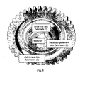
- Fig. 1 shows a possible embodiment of the gear according to the invention.
- the gear consists of three parts. These parts are an inner part (1) of the gear, a connecting element (2) of the gear and the ring gear (3) of the gear.
- the inner part (1) of the gear is designed so that it can be connected for example via a drive shaft with a motor.
- the motor or the drive shaft are mentioned here only as an example as possible cause of micro-vibrations.
- the invention is also successfully applicable to other sources of vibration, in particular micro-vibrations.
- the connecting element (2) is designed such that the vibrations, in particular micro-vibrations, which are caused by the drive shaft of the motor and act on the sprocket (3) are reduced by the reduced rigidity (inertia of the system).
- the connecting element (2) according to the invention frictionally connected to the inner part (1) and the sprocket (3).
- the achieved reduction factor is dependent on the thickness and the rigidity of the connecting element (2).
- the rigidity of the connecting element (2) which may be formed for example as a single sheets or ring.
- the connecting element (2) of the gear formed as a molded plastic ring is the connecting element (2) of the gear formed as a molded plastic ring.
- the plastic ring serves as a force-transmitting element.
- silicone or resin systems for advantageous Abminderungseigenschaften the thickness of the plastic ring should be between 1/10 mm to several millimeters.
- a technical advantage of this embodiment is that the amplitude of the vibrations, in particular micro-vibrations, is reduced to a lower level. In this case, ten times lower amplitudes are achieved compared to the case without plastic ring. The effect of the vibrations, in particular micro-vibrations, of the motor on instruments and the satellites are thus minimized.
- the connecting element of the gear (2) formed as a spring plate.
- the spring plate serves as a force-transmitting element. This was milled out of the gear or inserted in grooves.
- the spring plate is made of aluminum, titanium or spring steel.
- the thickness of the spring plate should be at least 0.1 mm.
- a technical advantage of this embodiment is that the amplitude of vibrations, in particular micro-vibrations, is reduced to a lower level. Ten times lower amplitudes are achieved compared to the case without spring plate. The effect of the vibrations, in particular micro-vibrations, of the motor on instruments and the satellites are thus minimized.
Landscapes
- Engineering & Computer Science (AREA)
- General Engineering & Computer Science (AREA)
- Mechanical Engineering (AREA)
- Gears, Cams (AREA)
- Connection Of Motors, Electrical Generators, Mechanical Devices, And The Like (AREA)
- Vibration Prevention Devices (AREA)
Abstract
Description
- Die Erfindung betrifft ein Zahnrad und insbesondere ein Zahnrad, welches aus mehreren Komponenten besteht. Das erfindungsgemäße Zahnrad lässt sich besonders vorteilhaft in Verbindung mit Schrittmotoren auf Satelliten verwenden. Die Anwendung des Zahnrads ist aber nicht auf diesen Anwendungsbereich beschränkt, sondern lässt sich vorteilhaft in jeder Anordnung oder Baueinheit verwenden, in welcher der Einfluss von Vibrationen, insbesondere Mikro-Vibrationen, abgemindert oder minimiert werden soll oder muss.
- Bei Verwendung von Schrittmotoren innerhalb von Anordnungen oder Baueinheiten werden Mikro-Vibrationen (Micro Jitter) durch das Rastmoment des Rotors verursacht. Diese Mikro-Vibrationen werden auf die Strukturteile der Anordnung bzw. der Baueinheit übertragen. Dies führt zum Beispiel zu Störungen in der Anordnung bzw. Baueinheit insbesondere in deren Instrumente oder zu Richtfehlern. Die Mikro-Vibrationen werden zum Beispiel durch Dauermagnete in dem rotierenden Teil des Motors produziert und als Beschleunigungen über das Zahnrad auf die Anordnung bzw. Baueinheit übertragen.
- Es ist eine Aufgabe der Erfindung ein Zahnrad so auszulegen, dass Wirkungen von Vibrationen, insbesondere von Mikro-Vibrationen, reduziert werden.
- Diese Aufgabe wird gelöst durch ein Zahnrad gemäß Anspruch 1.
- Vorteilhafte Aus- bzw. Weiterbildungen der Erfindung sind durch die Unteransprüche gegeben.
- Das erfindungsgemäße Zahnrad umfasst einen inneren Teil, welcher mit einem Verursacher von Vibrationen, insbesondere Mikro-Vibrationen, verbunden ist, z.B. mit der Antriebswelle eines Motors insbesondere eines Schrittmotors auf einem Satelliten, ein Verbindungselement und einen Zahnkranz, wobei das Verbindungselement so ausgebildet ist, dass die verursachten Vibrationen, insbesondere Mikro-Vibrationen, abgemindert werden. Dazu kann insbesondere das Verbindungselement kraftschlüssig mit dem inneren Teil des Zahnrads und dem Zahnkranz verbunden werden. Die Erfindung vermindert besonders vorteilhaft Vibrationen, insbesondere Mikro-Vibrationen, welche auf den Zahnkranz wirken.
- Gemäß einer Möglichkeit kann das Verbindungselement des Zahnrads als Federblech ausgebildet werden. Besonders vorteilhaft ist es, wenn das Federblech aus Aluminium, Titan oder Federstahl hergestellt ist. Besonders vorteilhaft ist es ferner, wenn das Federblech eine Dicke von mindestens 0,1 mm hat.
- Gemäß einer weiteren Möglichkeit kann das Verbindungselement des Zahnrads als vergossener Kunststoffring ausgebildet sein. Besonders vorteilhaft ist es, wenn der Kunststoffring aus elastischem synthetischem Material gefertigt ist, z.B. RTV-Kunststoff, Silikon oder einem Harzsystem. Besonders vorteilhaft ist es ferner, wenn der Kunststoffring eine Dicke von mindestens 1/10 mm bis zu mehreren Millimetern hat.
- Die Erfindung soll nachfolgend anhand von Ausführungsbeispielen näher erläutert werden.
- In den zugehörigen Zeichnungen zeigen:
- Fig. 1:
- Darstellung einer möglichen Ausführungsform des erfindungsgemäßen Zahnrads mit Kunststoffring
- Fig. 2:
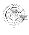
- Darstellung einer möglichen Ausführungsform des erfindungsgemäßen Zahnrads mit Federblech
-
Fig. 1 zeigt eine mögliche Ausführungsform des erfindungsgemäßen Zahnrads. Gemäß der Erfindung besteht das Zahnrad aus drei Teilen. Diese Teile sind ein innerer Teil (1) des Zahnrads, ein Verbindungselement (2) des Zahnrads und der Zahnkranz (3) des Zahnrads. - Der innere Teil (1) des Zahnrads ist dabei so ausgebildet, dass er zum Beispiel über eine Antriebswelle mit einem Motor verbunden werden kann. Der Motor bzw. die Antriebswelle werden hier nur beispielhaft als mögliche Verursacher von Mikro-Vibrationen genannt. Die Erfindung ist ebenso auf andere Verursacher von Vibrationen, insbesondere Mikro-Vibrationen, erfolgreich anwendbar.
- Das Verbindungselement (2) ist so ausgebildet, dass die Vibrationen, insbesondere Mikro-Vibrationen, welche von der Antriebswelle des Motors verursacht werden und auf den Zahnkranz (3) wirken, durch die reduzierte Steifigkeit (Trägheit des Systems) gemindert werden. Dazu ist das Verbindungselement (2) erfindungsgemäß kraftschlüssig mit dem inneren Teil (1) und dem Zahnkranz (3) verbunden. Der erreichte Reduktionsfaktor ist dabei von der Dicke und der Steifigkeit des Verbindungselements (2) abhängig.
- Eine besondere Bedeutung hat gemäß der Erfindung die Steifigkeit des Verbindungselements (2), welches zum Beispiel als Einzelbleche oder Ring ausgebildet sein kann.
- Gemäß der Ausführungsform in
Fig. 1 ist das Verbindungselement (2) des Zahnrads als vergossener Kunststoffring ausgebildet. Der Kunststoffring dient dabei als kraftübertragendes Element. Gemäß der Erfindung ist es besonders vorteilhaft, wenn der Kunststoffring aus elastischem synthetischem Material, z.B. RTV-Kunststoff (RTV-S = 961), Silikon oder Harzsystemen gefertigt ist. Für vorteilhafte Abminderungseigenschaften sollte die Dicke des Kunststoffrings zwischen 1/10 mm bis zu mehreren Millimetern betragen. - Ein technischer Vorteil dieser Ausführungsform ist es, dass die Amplitude der Vibrationen, insbesondere Mikro-Vibrationen, auf einen niedrigeren Level reduziert wird. Dabei werden zehnmal geringere Amplituden erzielt verglichen mit dem Fall ohne Kunststoffring. Die Einwirkung der Vibrationen, insbesondere Mikro-Vibrationen, des Motors auf Instrumente und den Satelliten werden somit minimiert.
- Gemäß der Ausführungsform in
Fig. 2 ist das Verbindungselement des Zahnrads (2) als Federblech ausgebildet. Das Federblech dient dabei als kraftübertragendes Element. Dieses wurde aus dem Zahnrad herausgefräst oder in Nuten eingesetzt. Gemäß der Erfindung ist es besonders vorteilhaft, wenn das Federblech aus Aluminium, Titan oder Federstahl gefertigt ist. Für vorteilhafte Schwingungseigenschaften sollte die Dicke des Federblechs mindestens 0,1 mm betragen. - Ein technischer Vorteil dieser Ausführungsform ist es, dass die Amplitude Vibrationen, insbesondere Mikro-Vibrationen, auf einen niedrigeren Level reduziert wird. Dabei werden zehnmal geringere Amplituden erzielt verglichen mit dem Fall ohne Federblech. Die Einwirkung der Vibrationen, insbesondere Mikro-Vibrationen, des Motors auf Instrumente und den Satelliten werden somit minimiert.
Claims (11)
- Zahnrad umfassend einen inneren Teil (1), welcher mit einem Verursacher von Vibrationen verbunden ist, ein Verbindungselement (2) und einen Zahnkranz (3), wobei das Verbindungselement so ausgebildet ist, dass die verursachten Vibrationen abgemindert werden.
- Zahnrad nach Anspruch 1, dadurch gekennzeichnet, dass das Verbindungselement (2) kraftschlüssig mit dem inneren Teil (1) des Zahnrads und dem Zahnkranz (3) verbunden ist.
- Zahnrad nach Anspruch 1 oder 2, dadurch gekennzeichnet, dass das Verbindungselement (2) des Zahnrads als Federblech ausgebildet ist.
- Zahnrad nach Anspruch 3, dadurch gekennzeichnet, dass das Federblech aus Aluminium, Titan oder Federstahl hergestellt ist.
- Zahnrad nach Anspruch 3 oder 4, dadurch gekennzeichnet, dass das Federblech eine Dicke von mindestens 0,1 mm hat.
- Zahnrad nach Anspruch 1 oder 2, dadurch gekennzeichnet, dass das Verbindungselement (2) des Zahnrads als vergossener Kunststoffring ausgebildet ist.
- Zahnrad nach Anspruch 6, dadurch gekennzeichnet, dass der Kunststoffring aus elastischem synthetischen Material hergestellt ist.
- Zahnrad nach Anspruch 7, dadurch gekennzeichnet, dass als elastisches synthetisches Material RTV-Kunststoff, Silikon oder Harzsystem verwendet wird.
- Zahnrad nach Anspruch 6, 7 oder 8, dadurch gekennzeichnet, dass der Kunststoffring eine Dicke von mindestens 1/10 mm hat.
- Zahnrad nach einem der vorhergenannten Ansprüche, dadurch gekennzeichnet, dass der innere Teil (1) des Zahnrads über eine Antriebswelle mit einem Motor verbunden ist.
- Zahnrad nach Anspruch 10, dadurch gekennzeichnet, dass der Motor ein Schrittmotor auf einem Satelliten ist.
Applications Claiming Priority (1)
| Application Number | Priority Date | Filing Date | Title |
|---|---|---|---|
| DE102012001703A DE102012001703A1 (de) | 2012-01-31 | 2012-01-31 | Zahnrad |
Publications (2)
| Publication Number | Publication Date |
|---|---|
| EP2623820A1 true EP2623820A1 (de) | 2013-08-07 |
| EP2623820B1 EP2623820B1 (de) | 2020-04-29 |
Family
ID=47594486
Family Applications (1)
| Application Number | Title | Priority Date | Filing Date |
|---|---|---|---|
| EP13000229.8A Active EP2623820B1 (de) | 2012-01-31 | 2013-01-17 | Zahnrad |
Country Status (3)
| Country | Link |
|---|---|
| US (1) | US9556949B2 (de) |
| EP (1) | EP2623820B1 (de) |
| DE (1) | DE102012001703A1 (de) |
Cited By (5)
| Publication number | Priority date | Publication date | Assignee | Title |
|---|---|---|---|---|
| DE102014225192A1 (de) | 2014-02-13 | 2015-08-13 | Miba Sinter Austria Gmbh | Zahnrad |
| DE102014225990A1 (de) | 2014-02-13 | 2015-08-13 | Metaldyne International Deutschland Gmbh | Zahnrad |
| CN107956807A (zh) * | 2017-11-29 | 2018-04-24 | 安徽辰物智能科技有限公司 | 一种电机齿轮啮合机构 |
| DE102019134083A1 (de) | 2019-01-04 | 2020-07-09 | Miba Sinter Austria Gmbh | Zahnrad |
| AT522070B1 (de) * | 2019-03-13 | 2020-08-15 | Miba Sinter Austria Gmbh | Zahnrad |
Families Citing this family (4)
| Publication number | Priority date | Publication date | Assignee | Title |
|---|---|---|---|---|
| KR102794622B1 (ko) | 2019-12-26 | 2025-04-15 | 엘지전자 주식회사 | 직렬탄성 구동기 |
| KR102794615B1 (ko) * | 2019-12-26 | 2025-04-15 | 엘지전자 주식회사 | 직렬탄성 구동기 |
| USD956841S1 (en) * | 2020-04-01 | 2022-07-05 | Robotis Co., Ltd. | Gear for actuator |
| USD1103234S1 (en) * | 2023-08-18 | 2025-11-25 | Shenzhen Huadian Lighting Co., Ltd. | Gear |
Citations (10)
| Publication number | Priority date | Publication date | Assignee | Title |
|---|---|---|---|---|
| DE311406C (de) * | ||||
| DE433120C (de) * | 1923-03-16 | 1926-08-23 | Esslingen Maschf | Zahnrad mit gedaempfter Federung |
| DE908317C (de) * | 1951-10-05 | 1954-04-05 | Licentia Gmbh | Rohling fuer Getrieberaeder od. dgl. |
| DE1300408B (de) * | 1963-10-21 | 1969-07-31 | Telefunken Patent | Zahnrad fuer einen spielfreien Zahntrieb |
| DE7135220U (de) * | 1972-05-18 | Robert Bosch Hausgeraete Gmbh | Schwingungsgedämpftes Getrieberad, insbesondere Zahnrad | |
| DE2419189A1 (de) * | 1974-04-20 | 1975-10-23 | Vdo Schindling | Elektrische uhr |
| DE2714020A1 (de) * | 1977-03-30 | 1978-10-12 | Werner Beiter | Zahnrad aus kunststoff und verfahren zu seiner herstellung |
| FR2438764A1 (fr) * | 1978-10-11 | 1980-05-09 | Magneti Marelli Spa | Dispositif pour l'accouplement a torsion elastique entre moyeu et roue, notamment pour moteur-reducteurs de puissance limitee |
| GB2126686A (en) * | 1982-09-09 | 1984-03-28 | Davall Moulded Gears | Rotatable toothed drive element |
| DE9205374U1 (de) * | 1992-04-18 | 1992-06-25 | Friedrich, Bernd, 8502 Zirndorf | Getriebeachsen und Getriebezahnräder unter ständigem Federdruck mit spielfreien Lauf zur Laufgeräuschdämpfung |
Family Cites Families (26)
| Publication number | Priority date | Publication date | Assignee | Title |
|---|---|---|---|---|
| US288134A (en) * | 1883-11-06 | Gear-wheel | ||
| DD255649A (de) * | ||||
| US37634A (en) * | 1863-02-10 | Improvement in cog-wheels | ||
| US623883A (en) * | 1899-04-25 | Cushioned car-wheel | ||
| DE255649C (de) | 1912-06-11 | |||
| US1427721A (en) * | 1922-04-17 | 1922-08-29 | Martin O Christenson | Noiseless gear wheel |
| US1666576A (en) * | 1925-02-05 | 1928-04-17 | Formica Insulation Company | Silent gear and method of manufacture |
| US1771370A (en) * | 1926-04-13 | 1930-07-22 | Continental Diamond Fibre Co | Mechanical element |
| US1928763A (en) * | 1931-02-12 | 1933-10-03 | Budd Wheel Co | Gear |
| US2307129A (en) * | 1940-04-05 | 1943-01-05 | Int Projector Corp | Shockproof gear |
| CH223124A (fr) * | 1940-09-27 | 1942-08-31 | Tissages A Brechard Sa D | Procédé de fixation d'un organe sur un arbre. |
| DE1808162U (de) * | 1958-02-12 | 1960-03-17 | Bayer Ag | Schwingungsdaempfendes zahnrad. |
| NL290281A (nl) * | 1962-03-17 | 1968-06-10 | Demag Ag | Tandrad met schuine vertanding |
| US3385127A (en) * | 1963-03-06 | 1968-05-28 | Shin Mitsubishi Jukogyo Kk | Gears formed of sheet metal and liquids |
| GB1242063A (en) | 1967-11-10 | 1971-08-11 | Atomic Energy Authority Uk | Improvements in or relating to the detection and measurement of movement |
| US4078445A (en) * | 1977-01-05 | 1978-03-14 | Kiser Jr Cecil M | Composite sprocket or the like |
| DE3033250A1 (de) * | 1980-09-04 | 1982-04-08 | Stahl Gmbh & Co Maschinenfabrik, 7140 Ludwigsburg | Zahnradantrieb |
| DE3153109C2 (de) * | 1981-03-27 | 1986-02-13 | Jagenberg AG, 4000 Düsseldorf | Geräuschgedämpftes Maschinenelement |
| FR2641351A1 (fr) * | 1988-12-29 | 1990-07-06 | Alcatel Business Systems | Pignon anti-bruit |
| US5927149A (en) * | 1995-07-14 | 1999-07-27 | The United States Of America As Represented By The Secretary Of The Navy | High-torque quiet gear |
| DE19856100C2 (de) * | 1998-12-04 | 2001-08-23 | Siemens Ag | Getriebemotor-Stellantrieb, insbesondere motorischer Schließteil-Antrieb für ein Kraftfahrzeug |
| US6959682B2 (en) * | 2002-09-05 | 2005-11-01 | General Motors Corporation | Engine balancer with chain drive vibration isolation |
| JP4375720B2 (ja) * | 2003-12-19 | 2009-12-02 | 株式会社エンプラス | 樹脂歯車 |
| DE102006058467B4 (de) * | 2006-12-12 | 2017-06-29 | Vibracoustic Gmbh | Zahnrad mit Elastomereinlage |
| JP4907577B2 (ja) * | 2008-03-19 | 2012-03-28 | 株式会社エンプラス | 歯車装置 |
| US9328816B2 (en) * | 2010-12-14 | 2016-05-03 | Gates Corporation | Isolator decoupler |
-
2012
- 2012-01-31 DE DE102012001703A patent/DE102012001703A1/de not_active Ceased
-
2013
- 2013-01-17 EP EP13000229.8A patent/EP2623820B1/de active Active
- 2013-01-30 US US13/753,966 patent/US9556949B2/en active Active
Patent Citations (10)
| Publication number | Priority date | Publication date | Assignee | Title |
|---|---|---|---|---|
| DE311406C (de) * | ||||
| DE7135220U (de) * | 1972-05-18 | Robert Bosch Hausgeraete Gmbh | Schwingungsgedämpftes Getrieberad, insbesondere Zahnrad | |
| DE433120C (de) * | 1923-03-16 | 1926-08-23 | Esslingen Maschf | Zahnrad mit gedaempfter Federung |
| DE908317C (de) * | 1951-10-05 | 1954-04-05 | Licentia Gmbh | Rohling fuer Getrieberaeder od. dgl. |
| DE1300408B (de) * | 1963-10-21 | 1969-07-31 | Telefunken Patent | Zahnrad fuer einen spielfreien Zahntrieb |
| DE2419189A1 (de) * | 1974-04-20 | 1975-10-23 | Vdo Schindling | Elektrische uhr |
| DE2714020A1 (de) * | 1977-03-30 | 1978-10-12 | Werner Beiter | Zahnrad aus kunststoff und verfahren zu seiner herstellung |
| FR2438764A1 (fr) * | 1978-10-11 | 1980-05-09 | Magneti Marelli Spa | Dispositif pour l'accouplement a torsion elastique entre moyeu et roue, notamment pour moteur-reducteurs de puissance limitee |
| GB2126686A (en) * | 1982-09-09 | 1984-03-28 | Davall Moulded Gears | Rotatable toothed drive element |
| DE9205374U1 (de) * | 1992-04-18 | 1992-06-25 | Friedrich, Bernd, 8502 Zirndorf | Getriebeachsen und Getriebezahnräder unter ständigem Federdruck mit spielfreien Lauf zur Laufgeräuschdämpfung |
Cited By (10)
| Publication number | Priority date | Publication date | Assignee | Title |
|---|---|---|---|---|
| DE102014225192A1 (de) | 2014-02-13 | 2015-08-13 | Miba Sinter Austria Gmbh | Zahnrad |
| DE102014225990A1 (de) | 2014-02-13 | 2015-08-13 | Metaldyne International Deutschland Gmbh | Zahnrad |
| US9856964B2 (en) | 2014-02-13 | 2018-01-02 | Miba Sinter Austria Gmbh | Gear |
| DE102014225990B4 (de) | 2014-02-13 | 2023-05-04 | Metaldyne International Deutschland Gmbh | Zahnrad |
| CN107956807A (zh) * | 2017-11-29 | 2018-04-24 | 安徽辰物智能科技有限公司 | 一种电机齿轮啮合机构 |
| DE102019134083A1 (de) | 2019-01-04 | 2020-07-09 | Miba Sinter Austria Gmbh | Zahnrad |
| AT521959A4 (de) * | 2019-01-04 | 2020-07-15 | Miba Sinter Austria Gmbh | Zahnrad |
| AT521959B1 (de) * | 2019-01-04 | 2020-07-15 | Miba Sinter Austria Gmbh | Zahnrad |
| AT522070B1 (de) * | 2019-03-13 | 2020-08-15 | Miba Sinter Austria Gmbh | Zahnrad |
| AT522070A4 (de) * | 2019-03-13 | 2020-08-15 | Miba Sinter Austria Gmbh | Zahnrad |
Also Published As
| Publication number | Publication date |
|---|---|
| US20130192403A1 (en) | 2013-08-01 |
| US9556949B2 (en) | 2017-01-31 |
| DE102012001703A1 (de) | 2013-08-01 |
| EP2623820B1 (de) | 2020-04-29 |
Similar Documents
| Publication | Publication Date | Title |
|---|---|---|
| EP2623820A1 (de) | Zahnrad | |
| DE102021105499B4 (de) | Rotor für eine Axialflussmaschine | |
| DE69007243T2 (de) | Rotor eines Motors mit Magneten. | |
| DE102009019056A1 (de) | Servomotor und Rotor dafür | |
| DE102016216888A1 (de) | Antriebsvorrichtung für einen Fensterheber, mit einem Lagerelement zum Fixieren eines Stators in einem Gehäuse | |
| DE102015203908A1 (de) | Rotor für einen Elektromotor sowie zugehörige Motorwelle | |
| EP2930825A1 (de) | Montage von Permanentmagneten auf einem Rotor einer elektrischen Maschine | |
| DE102019214087A1 (de) | Verbindung zumindest zweier Komponenten eines Lüfters und Verfahren zum Verbinden der zwei Komponenten des Lüfters miteinander | |
| DE102016221162A1 (de) | Getriebemotorantrieb mit verbesserter Geräuschisolierung | |
| DE102012105820A1 (de) | Elektrische Ölpumpe für ein Hybridfahrzeug | |
| EP3032724A1 (de) | Sekundärteil mit Schablone | |
| DE102020203487A1 (de) | Rotor eines Elektromotors | |
| EP3261221B1 (de) | Rotor für eine elektrische maschine, elektrische maschine mit dem rotor und herstellungsverfahren für den rotor | |
| DE102011054955B4 (de) | Rotorbaugruppe eines Gleichstrommotors | |
| EP3157140A1 (de) | Drehmomentoptimierter rotor und elektrokleinmotor mit einem derartigen rotor | |
| DE19708524C2 (de) | Elektromotor für Kraftfahrzeuge | |
| EP3261224B1 (de) | Elektrische maschine mit einem rotor und herstellungsverfahren für die elektrische maschine | |
| DE102011051090A1 (de) | Antriebsvorrichtung sowie Scheibenwischervorrichtung mit Antriebsvorrichtung | |
| DE102010012322A1 (de) | Rotor für eine elektrische Maschine | |
| DE20315609U1 (de) | Elektromotor | |
| DE102012020434A1 (de) | Elektrischer Dämpfer für ein Kraftfahrzeug | |
| DE102019119334A1 (de) | Nockenwellenversteller | |
| DE102013108827B4 (de) | Lüftereinheit mit einem Axiallüfter | |
| DE102019122603A1 (de) | Rotorvorrichtung und Statorvorrichtung für einen flachen bürstenlosen elektrischen Motor sowie flacher, bürstenloser elektrischer Motor für ein Dachsystem eines Automobils | |
| DE202011003307U1 (de) | Elektrische Maschine und Antiblockiervorrichtung |
Legal Events
| Date | Code | Title | Description |
|---|---|---|---|
| PUAI | Public reference made under article 153(3) epc to a published international application that has entered the european phase |
Free format text: ORIGINAL CODE: 0009012 |
|
| AK | Designated contracting states |
Kind code of ref document: A1 Designated state(s): AL AT BE BG CH CY CZ DE DK EE ES FI FR GB GR HR HU IE IS IT LI LT LU LV MC MK MT NL NO PL PT RO RS SE SI SK SM TR |
|
| AX | Request for extension of the european patent |
Extension state: BA ME |
|
| 17P | Request for examination filed |
Effective date: 20140203 |
|
| RAP1 | Party data changed (applicant data changed or rights of an application transferred) |
Owner name: AIRBUS DS GMBH |
|
| STAA | Information on the status of an ep patent application or granted ep patent |
Free format text: STATUS: EXAMINATION IS IN PROGRESS |
|
| 17Q | First examination report despatched |
Effective date: 20171204 |
|
| RAP1 | Party data changed (applicant data changed or rights of an application transferred) |
Owner name: AIRBUS DEFENCE AND SPACE GMBH |
|
| GRAP | Despatch of communication of intention to grant a patent |
Free format text: ORIGINAL CODE: EPIDOSNIGR1 |
|
| STAA | Information on the status of an ep patent application or granted ep patent |
Free format text: STATUS: GRANT OF PATENT IS INTENDED |
|
| INTG | Intention to grant announced |
Effective date: 20191213 |
|
| GRAS | Grant fee paid |
Free format text: ORIGINAL CODE: EPIDOSNIGR3 |
|
| GRAA | (expected) grant |
Free format text: ORIGINAL CODE: 0009210 |
|
| STAA | Information on the status of an ep patent application or granted ep patent |
Free format text: STATUS: THE PATENT HAS BEEN GRANTED |
|
| AK | Designated contracting states |
Kind code of ref document: B1 Designated state(s): AL AT BE BG CH CY CZ DE DK EE ES FI FR GB GR HR HU IE IS IT LI LT LU LV MC MK MT NL NO PL PT RO RS SE SI SK SM TR |
|
| REG | Reference to a national code |
Ref country code: GB Ref legal event code: FG4D Free format text: NOT ENGLISH |
|
| REG | Reference to a national code |
Ref country code: CH Ref legal event code: EP |
|
| REG | Reference to a national code |
Ref country code: DE Ref legal event code: R096 Ref document number: 502013014633 Country of ref document: DE |
|
| REG | Reference to a national code |
Ref country code: AT Ref legal event code: REF Ref document number: 1263804 Country of ref document: AT Kind code of ref document: T Effective date: 20200515 |
|
| REG | Reference to a national code |
Ref country code: IE Ref legal event code: FG4D Free format text: LANGUAGE OF EP DOCUMENT: GERMAN |
|
| REG | Reference to a national code |
Ref country code: NL Ref legal event code: MP Effective date: 20200429 |
|
| REG | Reference to a national code |
Ref country code: LT Ref legal event code: MG4D |
|
| PG25 | Lapsed in a contracting state [announced via postgrant information from national office to epo] |
Ref country code: GR Free format text: LAPSE BECAUSE OF FAILURE TO SUBMIT A TRANSLATION OF THE DESCRIPTION OR TO PAY THE FEE WITHIN THE PRESCRIBED TIME-LIMIT Effective date: 20200730 Ref country code: PT Free format text: LAPSE BECAUSE OF FAILURE TO SUBMIT A TRANSLATION OF THE DESCRIPTION OR TO PAY THE FEE WITHIN THE PRESCRIBED TIME-LIMIT Effective date: 20200831 Ref country code: IS Free format text: LAPSE BECAUSE OF FAILURE TO SUBMIT A TRANSLATION OF THE DESCRIPTION OR TO PAY THE FEE WITHIN THE PRESCRIBED TIME-LIMIT Effective date: 20200829 Ref country code: SE Free format text: LAPSE BECAUSE OF FAILURE TO SUBMIT A TRANSLATION OF THE DESCRIPTION OR TO PAY THE FEE WITHIN THE PRESCRIBED TIME-LIMIT Effective date: 20200429 Ref country code: LT Free format text: LAPSE BECAUSE OF FAILURE TO SUBMIT A TRANSLATION OF THE DESCRIPTION OR TO PAY THE FEE WITHIN THE PRESCRIBED TIME-LIMIT Effective date: 20200429 Ref country code: FI Free format text: LAPSE BECAUSE OF FAILURE TO SUBMIT A TRANSLATION OF THE DESCRIPTION OR TO PAY THE FEE WITHIN THE PRESCRIBED TIME-LIMIT Effective date: 20200429 Ref country code: NO Free format text: LAPSE BECAUSE OF FAILURE TO SUBMIT A TRANSLATION OF THE DESCRIPTION OR TO PAY THE FEE WITHIN THE PRESCRIBED TIME-LIMIT Effective date: 20200729 |
|
| PG25 | Lapsed in a contracting state [announced via postgrant information from national office to epo] |
Ref country code: BG Free format text: LAPSE BECAUSE OF FAILURE TO SUBMIT A TRANSLATION OF THE DESCRIPTION OR TO PAY THE FEE WITHIN THE PRESCRIBED TIME-LIMIT Effective date: 20200729 Ref country code: HR Free format text: LAPSE BECAUSE OF FAILURE TO SUBMIT A TRANSLATION OF THE DESCRIPTION OR TO PAY THE FEE WITHIN THE PRESCRIBED TIME-LIMIT Effective date: 20200429 Ref country code: LV Free format text: LAPSE BECAUSE OF FAILURE TO SUBMIT A TRANSLATION OF THE DESCRIPTION OR TO PAY THE FEE WITHIN THE PRESCRIBED TIME-LIMIT Effective date: 20200429 Ref country code: RS Free format text: LAPSE BECAUSE OF FAILURE TO SUBMIT A TRANSLATION OF THE DESCRIPTION OR TO PAY THE FEE WITHIN THE PRESCRIBED TIME-LIMIT Effective date: 20200429 |
|
| PG25 | Lapsed in a contracting state [announced via postgrant information from national office to epo] |
Ref country code: AL Free format text: LAPSE BECAUSE OF FAILURE TO SUBMIT A TRANSLATION OF THE DESCRIPTION OR TO PAY THE FEE WITHIN THE PRESCRIBED TIME-LIMIT Effective date: 20200429 Ref country code: NL Free format text: LAPSE BECAUSE OF FAILURE TO SUBMIT A TRANSLATION OF THE DESCRIPTION OR TO PAY THE FEE WITHIN THE PRESCRIBED TIME-LIMIT Effective date: 20200429 |
|
| PG25 | Lapsed in a contracting state [announced via postgrant information from national office to epo] |
Ref country code: RO Free format text: LAPSE BECAUSE OF FAILURE TO SUBMIT A TRANSLATION OF THE DESCRIPTION OR TO PAY THE FEE WITHIN THE PRESCRIBED TIME-LIMIT Effective date: 20200429 Ref country code: EE Free format text: LAPSE BECAUSE OF FAILURE TO SUBMIT A TRANSLATION OF THE DESCRIPTION OR TO PAY THE FEE WITHIN THE PRESCRIBED TIME-LIMIT Effective date: 20200429 Ref country code: IT Free format text: LAPSE BECAUSE OF FAILURE TO SUBMIT A TRANSLATION OF THE DESCRIPTION OR TO PAY THE FEE WITHIN THE PRESCRIBED TIME-LIMIT Effective date: 20200429 Ref country code: CZ Free format text: LAPSE BECAUSE OF FAILURE TO SUBMIT A TRANSLATION OF THE DESCRIPTION OR TO PAY THE FEE WITHIN THE PRESCRIBED TIME-LIMIT Effective date: 20200429 Ref country code: SM Free format text: LAPSE BECAUSE OF FAILURE TO SUBMIT A TRANSLATION OF THE DESCRIPTION OR TO PAY THE FEE WITHIN THE PRESCRIBED TIME-LIMIT Effective date: 20200429 Ref country code: DK Free format text: LAPSE BECAUSE OF FAILURE TO SUBMIT A TRANSLATION OF THE DESCRIPTION OR TO PAY THE FEE WITHIN THE PRESCRIBED TIME-LIMIT Effective date: 20200429 Ref country code: ES Free format text: LAPSE BECAUSE OF FAILURE TO SUBMIT A TRANSLATION OF THE DESCRIPTION OR TO PAY THE FEE WITHIN THE PRESCRIBED TIME-LIMIT Effective date: 20200429 |
|
| REG | Reference to a national code |
Ref country code: DE Ref legal event code: R097 Ref document number: 502013014633 Country of ref document: DE |
|
| PG25 | Lapsed in a contracting state [announced via postgrant information from national office to epo] |
Ref country code: SK Free format text: LAPSE BECAUSE OF FAILURE TO SUBMIT A TRANSLATION OF THE DESCRIPTION OR TO PAY THE FEE WITHIN THE PRESCRIBED TIME-LIMIT Effective date: 20200429 Ref country code: PL Free format text: LAPSE BECAUSE OF FAILURE TO SUBMIT A TRANSLATION OF THE DESCRIPTION OR TO PAY THE FEE WITHIN THE PRESCRIBED TIME-LIMIT Effective date: 20200429 |
|
| PLBE | No opposition filed within time limit |
Free format text: ORIGINAL CODE: 0009261 |
|
| STAA | Information on the status of an ep patent application or granted ep patent |
Free format text: STATUS: NO OPPOSITION FILED WITHIN TIME LIMIT |
|
| 26N | No opposition filed |
Effective date: 20210201 |
|
| PG25 | Lapsed in a contracting state [announced via postgrant information from national office to epo] |
Ref country code: SI Free format text: LAPSE BECAUSE OF FAILURE TO SUBMIT A TRANSLATION OF THE DESCRIPTION OR TO PAY THE FEE WITHIN THE PRESCRIBED TIME-LIMIT Effective date: 20200429 |
|
| PG25 | Lapsed in a contracting state [announced via postgrant information from national office to epo] |
Ref country code: MC Free format text: LAPSE BECAUSE OF FAILURE TO SUBMIT A TRANSLATION OF THE DESCRIPTION OR TO PAY THE FEE WITHIN THE PRESCRIBED TIME-LIMIT Effective date: 20200429 |
|
| REG | Reference to a national code |
Ref country code: CH Ref legal event code: PL |
|
| GBPC | Gb: european patent ceased through non-payment of renewal fee |
Effective date: 20210117 |
|
| PG25 | Lapsed in a contracting state [announced via postgrant information from national office to epo] |
Ref country code: LU Free format text: LAPSE BECAUSE OF NON-PAYMENT OF DUE FEES Effective date: 20210117 |
|
| REG | Reference to a national code |
Ref country code: BE Ref legal event code: MM Effective date: 20210131 |
|
| PG25 | Lapsed in a contracting state [announced via postgrant information from national office to epo] |
Ref country code: LI Free format text: LAPSE BECAUSE OF NON-PAYMENT OF DUE FEES Effective date: 20210131 Ref country code: CH Free format text: LAPSE BECAUSE OF NON-PAYMENT OF DUE FEES Effective date: 20210131 Ref country code: GB Free format text: LAPSE BECAUSE OF NON-PAYMENT OF DUE FEES Effective date: 20210117 |
|
| PG25 | Lapsed in a contracting state [announced via postgrant information from national office to epo] |
Ref country code: IE Free format text: LAPSE BECAUSE OF NON-PAYMENT OF DUE FEES Effective date: 20210117 |
|
| REG | Reference to a national code |
Ref country code: AT Ref legal event code: MM01 Ref document number: 1263804 Country of ref document: AT Kind code of ref document: T Effective date: 20210117 |
|
| PG25 | Lapsed in a contracting state [announced via postgrant information from national office to epo] |
Ref country code: AT Free format text: LAPSE BECAUSE OF NON-PAYMENT OF DUE FEES Effective date: 20210117 |
|
| PG25 | Lapsed in a contracting state [announced via postgrant information from national office to epo] |
Ref country code: BE Free format text: LAPSE BECAUSE OF NON-PAYMENT OF DUE FEES Effective date: 20210131 |
|
| PG25 | Lapsed in a contracting state [announced via postgrant information from national office to epo] |
Ref country code: HU Free format text: LAPSE BECAUSE OF FAILURE TO SUBMIT A TRANSLATION OF THE DESCRIPTION OR TO PAY THE FEE WITHIN THE PRESCRIBED TIME-LIMIT; INVALID AB INITIO Effective date: 20130117 |
|
| PG25 | Lapsed in a contracting state [announced via postgrant information from national office to epo] |
Ref country code: CY Free format text: LAPSE BECAUSE OF FAILURE TO SUBMIT A TRANSLATION OF THE DESCRIPTION OR TO PAY THE FEE WITHIN THE PRESCRIBED TIME-LIMIT Effective date: 20200429 |
|
| PG25 | Lapsed in a contracting state [announced via postgrant information from national office to epo] |
Ref country code: MK Free format text: LAPSE BECAUSE OF FAILURE TO SUBMIT A TRANSLATION OF THE DESCRIPTION OR TO PAY THE FEE WITHIN THE PRESCRIBED TIME-LIMIT Effective date: 20200429 |
|
| PG25 | Lapsed in a contracting state [announced via postgrant information from national office to epo] |
Ref country code: TR Free format text: LAPSE BECAUSE OF FAILURE TO SUBMIT A TRANSLATION OF THE DESCRIPTION OR TO PAY THE FEE WITHIN THE PRESCRIBED TIME-LIMIT Effective date: 20200429 |
|
| PG25 | Lapsed in a contracting state [announced via postgrant information from national office to epo] |
Ref country code: MT Free format text: LAPSE BECAUSE OF FAILURE TO SUBMIT A TRANSLATION OF THE DESCRIPTION OR TO PAY THE FEE WITHIN THE PRESCRIBED TIME-LIMIT Effective date: 20200429 |
|
| PGFP | Annual fee paid to national office [announced via postgrant information from national office to epo] |
Ref country code: DE Payment date: 20260121 Year of fee payment: 14 |
|
| PGFP | Annual fee paid to national office [announced via postgrant information from national office to epo] |
Ref country code: FR Payment date: 20260123 Year of fee payment: 14 |